Content:
In our century computer technology, smartphones and gadgets, it is difficult to find such a person who does not know what USB connectors are. Also, almost everyone understands words such as mini- and micro-USB connectors. After all, we use such things almost daily, which is natural. Similar connectors are found on the charger and on all computer peripherals.
But what if the wiring has moved away at the base, and there is no way to even understand what color and on what contact was soldered? This is where the knowledge should be applied, and what, now let's try to figure it out.
Wiring a similar plug, or, in other words, pinout USB wires, in its essence, does not carry anything super complicated in itself. Once you understand the sequence and colors, anyone who can handle a soldering iron can do this job.
But first you need to understand what a USB plug is.
What is a USB connector?
At its core, it is a connector with a variety of capabilities, ranging from USB power to the transfer of complex information data. A similar cable replaced the previously used options for connecting to a computer (PS / 2 ports, etc.). It is used today for all devices connected to personal computer Whether it's a mouse, flash drive, printer, camera or modem, joystick or keyboard - USB cables have become truly versatile.
There are three types of such connectors:
- 1.1 - its purpose is obsolete already peripherals with the ability to transfer information only one and a half megabits per second. Of course, after a slight modification by the manufacturer, the transmission speed rose to 12 Mbit / s, but with higher-speed options, it still could not stand the competition. Still, when u Apple there was already a connector supporting 400 Mbps. Now there are such types too, but there are very few of them, since faster USB cables, mini USB, and in general, the speed of USB occupies a special place in human life long ago. Everyone is in a hurry somewhere, in a hurry to live, there are people who practically do not sleep, and therefore, the faster the information is downloaded, the more preferable the connector, isn't it?
- 2.0. At the end of the last century, the second generation of such connectors was released. Here the manufacturer has already tried - the transmission speed has grown to almost 500 Mbit / s. And it was intended mainly for complicated gadgets, like digital camcorder.
- 3.0 is really high technology. The maximum data transfer rate of 5 Gb / s ensured the demand for this USB connector, which practically nullified the first and second versions. In the third series, the number of wires has been increased to nine versus four. However, the connector itself has not been modified, and therefore you can still use the types of the first and second series with it.
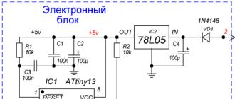
Pinout designations
Considering the pinout diagram, it is necessary to understand all the designations that are present on it. Usually indicated:

- Connector type - it can be active (A) and passive (B). A passive connection is a connection between a printer, scanner, etc. In general, a connector that only works for receiving information. Through active it is possible to receive and transmit data.
- The shape of the connector is female for female (F) and male for male (M).
- Connector sizes are regular, mini and micro.
For example USB AM, that is, active USB plug.
The wires should be arranged by color as follows (from left to right):
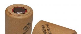
- Red wire - positive, constant voltage 5V. with a maximum current of 500 milliamperes.
- White wire - data-
- Green wire - data +
- Black wire - this wire is common, "ground", "minus". There is no tension on it.
But the mini and micro connectors include 5 wires with the following arrangement:
- Red, white and green wires are located in the same way as in the first option.
- ID - this wire in the B connectors is free. In "A" it must be shorted to a black wire.

Sometimes a separate wire without insulation may be present in the connector - this is the so-called "mass", which is soldered to the case.
According to the presented diagrams, the outer side is visible here. In order to solder the plug on your own, you need to take a mirror image of the picture, and as you probably realized, microUSB pinout is not at all more complicated than that of conventional USB connectors.
By the way, if the damaged parts of the cable are supposed to be used only for charging mobile phones, it will be more convenient, after looking at the colors of the wires, to solder only black and red. This connector is quite enough for a phone, it will charge it. What to do with the rest of the wires? You don't need to do anything with them.
Dragged chinese tablet with the words "does not charge."
Plugging the charger into the connector, I immediately realized that the connector was simply torn from the board. The most frequent breakdown. Well, let's get down to dissecting our client. To do this, with a tenacious gaze, we peer around the perimeter of the tablet and look for the screws that hold it together. Without thinking for a long time, we unscrew these screws
.JPG)
.JPG)
Voila!
.JPG)
I don't see any point in disassembling where the memory chip is located, percentages and other various mikruhi, since basically repairing the tablet involves replacing the touchscreen, display and connectors.
And here is the micro-USB charging connector. It is then that we need to replace it.
.JPG)
Now we need to get the board. Unscrew all the bolts that hold it. We also remove all the cables that go to the board. To do this, lift the clasp with your finger up.
.JPG)
If the wires interfere, we also solder them. I only soldered the battery. Since our connector is torn out with meat and is broken, we immediately throw it away. We begin to clean the seat for the new connector. To remove the solder in the through holes, we need a low-melting Wood or Rose alloy. To begin with, we abundantly tin the holes with this alloy, do not forget to also smear with gel flux. We heat the through hole together with the alloy using a soldering iron and then abruptly with the help of a desoldering pump pull out all the solder from the hole
.JPG)
I took the rubber tip for the desoldering pump from an old CD-shnoy car radio. I don't know what they are doing there, but there are even two of them.
Now we remove all excess solder from the contact pads (patches) using copper braid and a heated soldering iron
.JPG)
After this procedure, on the signal contacts using a soldering iron, solder and gel flux, we need to leave a bump of solder on each contact pad. Although this photo is from a different repair, the example should look something like this:

Now we take a new connector and smear its contacts with LTI-120 flux
.JPG)
.JPG)
.JPG)
A little about the connectors ... There are a lot of these micro USB connectors! Almost every manufacturer of tablets, phones and other bullshit uses their micro USB connectors. But I still found a way out ;-). I went to Aliexpress and bought myself a whole set at once. Here link... But now I have any kind of connectors for chinese phones and tablets ;-)
As soon as the connector is anointed, we tin-coat its contacts with solder. The main thing here is not to overdo it, otherwise the connector will not fit into the through holes on the board.
The rest is simple. We insert the connector, solder the through contacts on the other side, and then liberally grease the signal contacts of the connector with gel flux and press down each contact with the tip of the sting. (Sorry, it is inconvenient to take a photo, since I only have two hands, and there was no one nearby)
.JPG)
and then we clean the connector from poop and carbon deposits
.JPG)
We do everything as it was and check the tablet:
.JPG)
Charging is in progress. This completes the tablet repair.

Today, almost all modern and not only devices are equipped with usb connectors. A broken USB connector is a common problem that occurs due to accidental mechanical damage, such as damage when charging. If you are faced with such a problem, then this article will definitely help you.
To re-solder the USB connector yourself, you will need some tools such as:
- any soldering iron with a power of 25 watts,
- tweezers,
- easily fusible tin,
- solder,
- small curly screwdriver,
- scalpel or knife with a thin blade,
- magnifier.
Below is a step-by-step look at how to disassemble your device. The most important thing is to do everything very carefully.
At first, you need to unscrew all the fixing screws on your device. First, pry off the back cover by prying it open with a thin blade. With this we release the body clamps from the grooves, tilting the knife towards the screen.
Secondly, after removing the cover on the device, be sure to ground your soldering iron. Then solder the wire to the common body, and then the other end of the wire to the body of the soldering iron itself. These steps are necessary in order to protect the gadget from accidental static electricity that can discharge it. electronic components out of service. You also need to make an ESD wrist strap and ground it too.
Thirdly In order not to inadvertently close the electronic circuit and damage the components, you need to unsolder the wires from the battery.
And finally, we unscrew all the mounting screws on the board and turn it over, thereby we get directly to the micro usb connector itself.
As you understand, DIY repair can be quite problematic. Soldering micro usb is not an easy task for regular user... If you do not want to risk, then bring your device to us, to Smartkit, and we will be happy to solve your problem for a small price and quickly.
Due to the negligent attitude towards electronic devices (laptops, tablets, smartphones), USB sockets (connectors) are often loosened or completely broken. It is not always advisable to buy new equipment, especially if you can fix it yourself. This also applies to cords with a micro USB connector. Fixing them is as easy as soldering the charging socket on the tablet.
Micro USB repair begins with disassembling the tablet (or other gadget).
This requires a small set of tools:
- screwdriver;
- tweezers;
- scalpel (knife);
- low-voltage soldering iron or hot air gun.
First, unscrew all the screws holding the case (if any). The casing locks are released from the grooves - to do this, pry off the cover with a scalpel and carefully tilt the blade towards the screen.

It is imperative to take care of the safety of your smartphone. To do this, wear an antistatic wrist strap with grounding. Only a low-voltage soldering iron is used, which must also be grounded (for this you can solder one end of the wire to the minus (common body), to the other to the soldering iron itself). It is even better to use a soldering station - a hot air gun.
Disconnect the wires from the battery, otherwise components may be damaged if the circuit is accidentally shorted. Unscrew the screws securing the board, turn it over and inspect.
Damage types
There are different types of damage, so further actions depend on the type of malfunction. If the connector is faulty, then you will have to buy a new micro USB or look for a broken device with a working socket and replace it. When a working USB just came off, it is enough to restore the connections with a soldering iron. In the event of a malfunction of the plug on the cable, you must buy and solder a new one.
The connector is defective
In this case, you need to find a known working connector, for example, on an inoperative cell phone.
The micro usb will have to be soldered; for this, a scalpel is inserted between the board and the connector. It is necessary to unsolder the mounting tabs from the board, and then unsolder the micro USB output, heating them at the same time.
In this case, it is necessary to monitor the temperature so as not to deform the plastic parts. The thinner the soldering iron tip, the less chance of damaging the connector..
You should pay attention to the location of smd parts during installation, since the reverse installation is somewhat more complicated. Soldering USB is done upside-down.
A working connector came off
It is necessary to check the integrity of the tracks on the board by examining them with a magnifying glass. All damage will have to be repaired. To do this, first remove the varnish with a scalpel, and then tin the tracks with a soldering iron. Soldering the micro USB connector begins by attaching the mounting lugs. Before that, you can glue the connector to the board to make it less likely to break.
If other damage remains, then they take thin copper wires and fix them between the pins of the tracks and USB. If they are not fully restored, only the charging function will remain (without the possibility of data transfer). Also, the connected mouse will not work. If you are sure that everything has been restored correctly, then this indicates a malfunction of the USB itself.
Flash memory problems
If the connected flash drive does not work, then first you should check it for operability by connecting to other known working devices. If a serviceable drive does not work only with a repaired device, then errors were made during the repair.

Most likely, some damage to the bridges was not noticed - it is necessary to re-disassemble the hull and conduct an inspection. If visually everything is in order, it means that the malfunction is hidden, and further disassembly is performed only if it is not a pity to completely lose the device and waste time in vain.
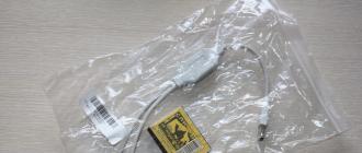
Replacing the plug on the charger
If the charger is in good working order, then for repair it is enough just to find or buy a plug micro usb for soldering.

The renovation will consist of the following:
- cut the wire charger and a donor cord so that the first has a tail of 10 cm, and the second of 15 cm;
- peel off the outer insulation 3 cm from the edge. Be careful not to damage the coating of the inner cores. To do this, first make a circular (across) and then a longitudinal (lengthwise) cut. Peel off the rubber with your fingers and release two veins;
- do the same with the tail of the new plug. You will see 4 wires, an aluminum shield and a copper braid. You only need a red and black vein, everything else can be cut off;
- to prevent shorting, shorten the red wire on one side and the black wire on the other. This will also avoid the bump;
- connect the exposed parts and insulate.

You can use electrical tape, heat shrink or tape. The wires can be simply twisted or soldered, soldering, of course, is more reliable.
If heat shrink tubing is used, fold the connections along the wire and close them. A hairdryer is brought to the material and gently heated. It is allowed to use a lighter, but bring it up gradually. After that, the wide tube is seated on the main cable. At this, the repair can be considered completed.
Now in devices you can often find usb connectors (u-es-bi, English Universal Serial Bus - "universal serial bus "). Due to accidental mechanical damage, for example, while the device is in charging mode, such a malfunction is often encountered - such as a break in the micro usb connector. You will learn how to solder the micro usb connector yourself in the article below.
If you love tinkering and know how to handle a soldering iron, then it will not be difficult for you to rewire the micro usb connector on the tablet yourself. To do this, we need tools: a 25 watt soldering iron, solder, easy fusible tin, tweezers, a small curly screwdriver, a scalpel or a knife with a thin blade, a magnifying glass.
How to disassemble a tablet (phone, laptop)?
The most important thing is that we do everything carefully and accurately!
For disassembly, we need:
- Screwdriwer set;
- Tweezers;
- Scalpel or knife;
- Soldering iron.
Procedure.
Step 1. Unscrew all the fastening screws on the tablet or phone, remove the back cover by gently prying it off with a knife or scalpel, thereby freeing the case latches from the grooves, tilting the blade towards the screen.

Step 2. After removing the cover on the tablet (phone), you need to ground the soldering iron, solder the wire to the common body (minus) and then the other end of the wire to the body of the soldering iron itself. This must be done in order to protect the tablet from accidental static electricity, which can damage its electronic components. You should also make an antistatic wrist strap and also ground it.
Step 4. After that, we unscrew all the fastening screws on the board and turn it over, thereby we get directly to the micro usb connector itself.
List of USB connector malfunctions
1. Micro usb connector has failed.
If the connector has become unusable and further repair is impossible, then it should be replaced. To do this, we need to find a knowingly working one, you can use an unnecessary or faulty one cell phone and unsolder the micro usb connector from the phone. To do this, take a scalpel and push it between the board and the connector, heating the mounting tabs of the micro usb connector, gradually lifting one side, then the other. Further, after the mounting tabs are soldered from the board, you need to take tweezers, since the connector heats up quickly, you should not overheat, because the plastic parts of the micro usb connector can melt and deform. After that, we unsolder the connector pins, they should be heated all at the same time. Pay attention to the installation, smd parts can be near the connector and if soldering is not accurate, they can be soldered or burned, be careful and therefore the soldering iron tip must be thin. The sequence for unsoldering the connector is the same and dismantling the micro usb connector on the tablet should be done in a similar way.
2.Micro usb connector is functional, but disconnected from the main board.
In this case, it is worth paying attention to the integrity of the tracks themselves, for this we take a magnifying glass and inspect the installation, if the tracks are intact on the board, then well, if not, then we will have to restore them. It is necessary to find all the ends of the torn off tracks and carefully clean them with a scalpel (clean the varnish), then tin with a soldering iron. After that, we take the micro usb connector itself and solder the fastening tabs of the connector to the board, I advise you to pre-glue the connector to the board before soldering, this will reduce the likelihood of repeated breakage. It remains small, solder the leads, if the tracks are intact, then it will not be difficult, but if not, we do the following: we take thin copper wires (one hair of a stranded thin wire) and solder between the leads of the tracks and the connector. If, for some reason, it was not possible to restore all the tracks (the track under the electronic part is cut off and there is no way to track its location). In this case, it will be possible to do only for charging the tablet, while we need to restore only two tracks, two extreme outputs to the micro usb connector, the only drawback is the inability to connect the tablet to a computer and external devices.
P O P U L Y R N O E:
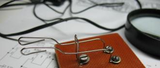
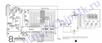
Motion(dynamic) means that the coil must be in motion to detect a metal object. Metal detector what I'm going to offer you now is a semi-professional device. The basis of the project was taken from old schemes, changed, improved and simplified. Also redesigned printed circuit board and the location of the components.
In amateur radio practice, it is often necessary to check the signal status in various parts of the device. In most cases, this is done using an oscilloscope. But such a device is not always at hand, and not every novice radio amateur can purchase it. Various probes can be of some help when you don't have an oscilloscope. For example, the one described in the proposed article.