Hello!
I want to show how a program is written to control technological equipment on a PLC.
Most often I dealt with a PLC made by Schneider Electric. The Quantum I have chosen for this task is the most powerful and expensive PLC of this manufacturer. It can control equipment with thousands of signals; naturally, no one will use it for a traffic light in real life.
I have never dealt with automation of traffic lights, so I came up with the algorithm myself. Here it is:
1. Traffic light for regulated pedestrian crossing. Those. traffic light for cars, traffic light for pedestrians and a button for pedestrians, by pressing which, a pedestrian notifies about the desire to cross the road.
2. After the start of the program, green lights up for cars and red for pedestrians.
3. After the pedestrian has pressed the button, green for cars flashes, then yellow, then red. After that, green lights up for pedestrians, after a predetermined time it starts flashing, red lights up for pedestrians, then yellow and red lights up for cars, then green.
4. During a specified period of time after a green light at a pedestrian traffic light, pressing the button by a pedestrian does not start the crossing algorithm. In this case, the transition algorithm starts only after the specified time has elapsed.
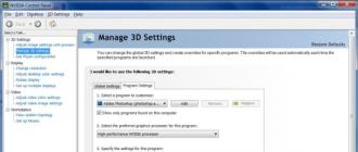
PLC programming is carried out in the Unity programming environment in the languages of the IEC 61131-3 standard. This standard includes 5 languages. For example, I have chosen the language of function blocks - FBD.
Here is the project browser in Unity:
Configuring the PLC: 
The PLC consists of a mounting panel, a power supply (1), a controller (2), a digital input module for 32 signals of 24V DC (4), a digital input module for 32 signals of 24V DC (5). In a real project, there can be dozens of mounting panels connected to one controller via different networks, and there can be hundreds of I / O modules.
We create variables of the required types in the variable editor: 
The variables associated with the channels of the I / O modules have an address that indicates which rack, module, and channel the signal is bound to.
The program consists of sections that are executed each scan cycle of the controller in order.
Simplified controller scan cycle looks like this:
1. Reading input signals from the input module into variables with addresses.
2. Execution of sections.
3. Writing values from variables with addresses to the output signals of the output modules.
4. Go to item 1.
Create a Clock section with a 0.5 second pulse generator. The TP block, when the input signal changes from 0 to 1, outputs a pulse of a given duration. 
Here and below, the screenshots of the sections are shown in animation mode, not edit mode. They display the values of the variables at the current time when connected to a PLC with a loaded program (numbers for numeric variables, green (1) -red (0) for boolean).
The Main section handles the main logic.
The SR block sets the output to 1 when S1 = 1 and resets the output to 0 when R = 1.
The R_TRIG block sets the output for 1 scan cycle to 1 when the input transitions from 0 to 1 (leading edge detector).
The F_TRIG block sets the output for 1 scan cycle to 1 when the input transitions from 1 to 0 (trailing edge detector).
The inButton variable bound to the button channel has been replaced in the section with inButtonForTest so that you can change its value on the controller simulator without real hardware. 
The Outputs section generates output signals for controlling traffic lights. 
Load the project into the controller simulator: 
The meaning of any variables can be viewed in the animation table: 
But for the convenience of debugging, you can make an operator screen with simple graphics, the animation of which is tied to variables: 
Trying to cross the road:
I did not expect that it would take 30 blocks to control such a simple object as a traffic light.
In the next article I will show how to write this program using all the languages of the IEC 61131-3 standard at the same time.
UPD. Fixed a mistake in the name of the standard.
When my son glued a dummy of a traffic light out of paper for the school, the thought came: "Why not assemble a working model of a traffic light for him on a microcontroller." On the Internet, there are many schemes and programs for them, implementing the principle of the simplest traffic light. But they are either too complicated for a toy (DC-DC converter, shift registers, etc.) or are presented only as an example of the simplest assembly language program. I want to present a schematic and assembly language program for a complete toy traffic light with some additional functionality. Moreover, it is assembled on a "penny" microcontroller according to the simplest scheme, which is important for beginners. Hopefully, this simple circuit will become the first real PIC-based design for many who are starting to learn programming PIC microcontrollers. Simple, but at the same time containing the basic techniques and attributes of programming, the program will make it easy to understand and experiment with it.
Everyone who deals with programming microcontrollers knows the basic principles of writing interrupt handlers: as short execution time and short code as possible, no loops and calls from the handler of other subroutines, etc. In this case, interrupts are allowed only on level changes (we cannot skip other interrupts, since they simply do not exist) and I, to simplify the program and its perception, considered it possible to deviate from these principles. Here in the interrupt handler there are loops, and a call to another subroutine, and (oh horror!) Even a transition to SLEEP mode. Therefore, in the title, the program is called "wrong". In this case, the interrupt handler is used as a regular subroutine, however, in other cases the above principles, of course, remain valid.
Brief characteristics of the device:
The device is a model of a street traffic light with a reliable simulation of its operation (switching colors, blinking green) and has additional functions: changing the switching frequency by pressing a button, blinking yellow mode, switching to sleep mode in manual and automatic modes, followed by switching on by pressing a button. This device can be used as a children's toy, as well as a visual aid in preschool institutions when teaching children how to behave on the roads.
So, let's move on to the description and consideration of the circuit.
The circuit is assembled on an inexpensive PIC12F629 microcontroller. The outputs GP0-GP2, GP4, GP5 (pins 7, b, 5, 3, 2), programmed as outputs, are used directly to control the LEDs. LEDs in each direction are combined into series groups, which minimizes the current consumption. Resistors R3-R8 limit the LED currents. In case of a strong difference in the output of LEDs of different colors, you will have to select the appropriate resistors. For me, for example, two groups of yellow color are connected in parallel and connected to one resistor, moreover, of the same rating as the rest and shine even a little brighter than the others (the recoil is greater).
In this circuit, the LEDs are fed 1.5 V more than the microcontroller from an additional element (in this case, when the output is off, the current does not pass to the output of the microcircuit, since a much higher voltage is required to open the transitions of two LEDs (at least 2.5 B). And even with both LEDs punctured (which is unlikely), the current through the internal protective diode to the plus of the power supply will be about 7.5 mA, which is much less than the permissible current. It is experimentally established that, despite a decrease in the current through the LEDs when the battery is discharged, the brightness of their glow remains at an acceptable level in the entire range of battery voltage. current, which made it possible to abandon the power switch (current consumption in sleep mode - 1-3 m kA).
The button for controlling the operating modes of the device is connected to the GP3 pin (pin 4), which is declared as a digital input in the configuration bits. When the button is pressed, an interrupt occurs, in the handler of which the following occurs. When pressed for a long time (more than 4 s), the device goes into sleep mode. With shorter presses, there is a sequential switching of the speed of the traffic light in a circle with the indication of the current speed according to the figure.

In the latter mode (red LEDs are on), the yellow flashing signal is activated. With a long press on the button (confirmed by the extinguishing of all LEDs), we go to normal operation with a change in the mode to a new one, if the button is not pressed for more than 6 seconds, the operation mode remains the same as before the button was pressed.
A charge of AA cells in sleep mode will last for at least a year, which is why the device does not have a power switch. The device goes into sleep mode also after 0.5 - 1 hour (depending on the speed of switching colors) without affecting the button. SLEEP mode is exited by any button press. Power is supplied to the microcontroller via pins 1 and 8. To save pins and simplify the design, the mode of the internal generator without external elements is enabled.
Small explanations for the program, which is given in the attachment.
Processing of button clicks is performed in subroutines: wait_butt __- waiting for pressing and registration for 6 seconds. without pressing, push_butt __- registration of the duration of pressing, wait_nobutt __- waiting for an unpressed button. When the traffic light state changes (yellow and blinking green), the values for the output port are read from the table in the tact__ subroutine (low or high nibbles). Likewise, the status indication when the button is pressed is from the ind__ subroutine. To switch to sleep mode after the expiration of the operating time, a forced transition to the interrupt processing routine occurs by software setting of the interrupt flag. By changing the constants CONST_MIN, CONST_REG, CONST_SL, you can change the green blinking period, the initial mode when the battery is connected, the operating time without impact until the transition to the SLEEP mode.
The printed circuit board is made of one-sided foil-clad fiberglass and has dimensions of 22x87 mm. The outermost LEDs are installed parallel to the board in different directions. The middle ones are installed one from the side of the installation of the parts, and the other from the side of the tracks with threading the leads into the holes of the board and fixing them from the side of the parts with a drop of solder, and from the side of the tracks by soldering to the corresponding tracks.
All resistors are 0.125W. LEDs can be taken any domestic or imported, preferably of the same type with a direct voltage drop at a current of 10 mA of about 2 Volts. Button - any without fixing. The microcontroller is installed on the block.
The configuration word is entered into memory automatically when the firmware is loaded (the "birdie" is installed only in the "PWRT" item, the rest of the items are "cleared", the "intOSC GP4" is set in the "oscillator" column). First, it is necessary to read the firmware from a clean microcircuit and write the value of the word at the end of the program memory at 03FF, which is required to adjust the frequency of the internal generator of a particular microcircuit instance. After loading the HEX file into the program, this value must be manually entered at 03FF. In this device, the frequency deviation is not critical, but you should still know that this microcircuit requires such a procedure. As a last resort, if the factory value is lost, you can do nothing - the program has taken measures for correct operation in this case.
The device is placed in a suitable plastic box. The corresponding holes are made for the LEDs in the box and lid. In my version, the traffic light itself and the base with the button and the battery are connected through a piece of plastic water pipe with a diameter of 20 mm.

The application contains: model, printed circuit board in LAY format, MPASM assembler program, HEX firmware file.
List of radioelements
| Designation | Type of | Denomination | Quantity | Note | Shop | My notebook |
|---|---|---|---|---|---|---|
| IC1 | MK PIC 8-bit | PIC12F629 | 1 | DIP | Into notepad | |
| R1 | Resistor | 3 kΩ | 1 | 0.125W | Into notepad | |
| R2 | Resistor | 100 ohm | 1 | 0.125W | Into notepad | |
| R3-R8 | Resistor | 200 Ohm | 6 | 0.125W | Into notepad | |
| HL1, HL2, HL9, HL10 | Light-emitting diode | AL307A | 4 | RED | Into notepad | |
| HL3, HL4, HL11, HL12 | Light-emitting diode |
Purpose of work. The purpose of the laboratory work is to debug C applications for the AVR microcontroller using the CVAVR compiler and the VMLAB simulator.
Work program
1. Install to directory C: \ CVAVR free version of the compiler CodeVisionAVR. In the C: \ CVAVR directory create a folder z1(task 1) for the files of the first project.
Start the compiler. To create a project file press: File -> new -> project -> OK -> No- go to the folder created for the project z1 and enter in the "file name" field: z1 - click "save" - the project configuration window will open
Go to the "With compiler" tab
Select MK (Chip) ATmega16
Set the clock frequency of MK (Clock) 4.0 MHz
Click on OK.
An open text file will appear in front of you Project Notes - z1.prj where you can write down your comments and thoughts on the project.
Now we need to create the main text file for us for typing the source text in C - its extension. C
Click: File -> New -> Source -> OK
file appeared untitled.c- press: File - Save As- enter in the "file name" field: z1.c and press Save.
You need to add the created file z1.c to the list of project files - open the project configuration menu: Project -> Configure.
In the dialog that opens, you need to select the "Files" shortcut and click the " Add". In the new dialog select the file" z1.c" and press " Open". The file is now included in the project.
Click: OK
Maximize (expand) the file window - z1.c
Now everything is ready for the actual programming, i.e. to the creation of the text of the program in the C language. The table below contains the text of the program for task 1, which implements the following technical task: Develop a device based on the ATmega16 microcontroller, which will display an 8-bit number in binary form with LEDs lit, starting from 0 and with a constant increase by 1. The device is powered by a constant stabilized voltage from 4 to 5.5 volts. The MC is clocked from a quartz resonator with a frequency of 4 MHz. A total of 8 LEDs are connected from the port pins A through current-limiting resistors to the power supply of the MK. LED switching should be performed with pauses of 65 ms.
|
#include #define PA_OUT DDRA = 0xFF/ * Replace everywhere in the program text PA_OUT on DDRA = 0xFF * / // ++++ MK initialization function ++++ void initialization (void) ( PA_OUT; // make the whole PORTA exit TCCR0 = 0x05;/ * enable timer to count, making one count every 1024 oscillations on the XTAL1 leg * / } Charper=0; // ++++ Main function ++++ void main (void) ( initialization ();/ * Call the MK initialization function - i.e. settings of the MK devices we need in accordance with the task * / //Endless cycle while (1) (// Do always PORTA = ~ (per++); while (! (TIFR & 0x01));// wait for the timer0 overflow flag to be set TIFR = 0x01;// clear the timer0 overflow flag }; // loop finished } // parenthesis for main () |
Write (without comments) the program to the program source window. Save changes: file -> SaveAll.
To compile the program, click the " Maketheproject".
Take a look at the folder of our project - z1. As a result of compilation, many new files appeared there. The main ones for us:
z1.hex - firmware file for "loading" into MK;
z1 __. с - copy of the file z1.c for simulators;
z1.cof - information linking the contents of files z1 __. c and z1.hex. This information allows you to observe the movement of the program directly through the C code when simulating in VMLAB. The specified files will be used in the VMLAB simulator. Only the firmware file is required for a real MK.
The following four files contain our program written in standard AVR assembler with reference to C text: z1.asm, z1.lst, z1.vec, z1.inc. The rest of the files are practically uninteresting.
2. Start VMLAB and open the created project: Project -> Open ProjectFile
Go to task 1 folder C: \ CVAVR \ z1 \ and type the file name z1_vm.prj of the project for VMLAB. After the phrase appears that such a file does not exist, VMLAB will offer to create it, with which you agree. In the window that appears, write down the text file below in the table without comments.
|
; Project file z1_vm.prj for simulation for task 1. ; Comments are written in VMLAB in only one line ; after semicolon; MK as if "stitched" with a file - z1.hex. After turning on the MK ; the lit LEDs show in binary form numbers from 0 .MICRO "ATmega16"; simulated MC .TOOLCHAIN "GENERIC" .TARGET "z1.hex"; what is "stitched" in MK .COFF "z1.cof" .SOURCE "z1 __. C" .POWER VDD = 5 VPP = 0; Power supply +5 volts; VSS is GND MK - "common" wire of the circuit; The voltages are measured against it .CLOCK 4meg; quartz frequency 4 MHz; More precisely, this is the clock frequency of the MK ; Entering a device diagram for task 1; 8 LEDs are connected by cathodes through resistors : nominal 560 Ohm to MK legs from 33 to 40 ; connect the resistor R1 to the D1_NODE node and to the PA0 pin of the MK; anode of the LED to the +5 V circuit. The remaining 7 LEDs ; are connected in the same way D1 VDD D1_NODE R1 D1_NODE PA0 560 D2 VDD D2_NODE R2 D2_NODE PA1 560 D3 VDD D3_NODE R3 D3_NODE PA2 560 D4 VDD D4_NODE R4 D4_NODE PA3 560 D5 VDD D5_NODE R5 D5_NODE PA4 560 D6 VDD D6_NODE R6 D6_NODE PA5 560 D7 VDD D7_NODE R7 D7_NODE PA6 560 D8 VDD D8_NODE R8 D8_NODE PA7 560 ; Signals on legs PA0 PA1 PA2; we will observe in the window of the virtual oscilloscope - "Scope" .PLOT V (PA0) V (PA1) V (PA2); Draw voltage graphs in the listed nodes of the circuit |
From the Project menu run Re-Build all ...
Through the View menu, open two components: SCOPE is the virtual storage oscilloscope of the simulator and the Control Panel is a panel that contains the LEDs we need and much more that we do not need yet.
Open the Code window using the Window menu (usually it opens immediately upon opening the project) - in this window you will see the text of the simulated program.
Pay attention to the Messages window - the service messages of the simulator appear in it as you work. A message should appear in the Messages window stating that it is successful and that everything is ready to run (Success! All ready to run). In addition, a green traffic light on the toolbar will light up - this is a button with which you can start the simulation.
Pressing the green traffic light is equivalent to applying a "1" to the RESET pin of the MC when the power is on, but not yet executing the program.
Three graphs appeared in the Scope window for the signals that we will observe. Set the vertical scale to 2 volts per division and the horizontal scale to 50 ms.
In the Code window, a gray field on the left and green squares appeared opposite the executable lines of the program code in C - by clicking on such a square, we can set a breakpoint for the program.
Place the three windows and the Control Panel on the computer screen so that you can see them all.
Click "traffic light" to start the simulation program. The program starts and stops - a message appears in the Messages window. Click on the "traffic light" again. The simulator stops again and reports that there was a reset from the "MK watchdog timer" - we did not tell the simulator that we were not using it. Click on the "traffic light" again - now the program will run continuously until we stop it.
Let the program simulate, and you watch what happens in the above windows. What is displayed in the Control Panel window besides the LEDs?
Watch the windows SCOPE and Code and behind the LEDs. In the window Code during the simulation, yellow stripes appear and grow, highlighting the lines of the executable program. The lengths of these highlights are proportional to the time during which the program executes the code of these lines.
How much current is drawn by the microcontroller from the power supply? Stop the simulation by pressing the red "Stop" octagon and measure the duration of the pulse period on the PA2 MK leg. How does it correspond to the calculated value? To measure the time interval in the SCOPE window of the VMLAB simulator, you need to set vertical cursors 1 and 2 at the boundaries of the measured interval and the time value between the two cursors will appear in the Cursor delta time field.
When measuring short repetitive intervals you can measure the time of several at once, and then divide the result by the number of such intervals between the measuring cursors.
Restart MK by clicking on the button with circular dark blue arrow... You kind of turn off and then reapply power to the MK, but create a "0" on the RESET leg of the MK - as a result of which the program does not start!
What is the function of the command PORTA=~(per++); ?
Provide in the report the diagram for connecting the LEDs to the MK.
3. Modify the program. Switch the LEDs to port C. Reduce the pause time between switching LEDs by 2 times.
To change the C code of a program, just start the CodeVisionAVR compiler (you do not need to turn off VMLAB!) And make the necessary changes, then compile the project. Next go to VMLAB, do deep restart and then Re-buid all. Everything! The changes are made and everything is ready for simulation again. Thus, the compiler and simulator work simultaneously in the same project folder and do not interfere, but help each other. Include the z1.c and z1_vm.prj files of the modified project in the report.
4. In the next project, we will display data on a character LCD display (liquid crystal display). The diagram of its connection to port A of the microcontroller is shown in Fig. 9.1 (the source of information is also indicated there, in which you can familiarize yourself with the problem being solved in more detail).
Run the compiler CodeVisionAVR, then the seed code generator " CodeWizardAVR" - by clicking gray gear to the left of the red bug ... Select ATmega16 and 4 MHz crystal frequency. Go to the LCD tab and specify PORTA and 16 characters.
After completing File ->Generate, SaveandExit, create a folder in the C: \ CVAVR directory z2(task 2) for files of a new project. Save the files z2.c, z2.prj and z2.cwp by pressing z2 three times. Look at the file of the initial code of the program generated by the wizard z2. c... What commands are used to initialize the LCD display? Is it possible to remove from the program commands that implement the initialization of peripheral devices that are not used in this task?

Rice. 9.1 - Typical wiring diagram for the LCD display
After the command
lcd_ init(16); // LCD 16 characters per line
add two lines:
lcd_ gotoxy(5,0); // display characters from the 6th position in the first line lcd_ putsf(" Hello! "); // counting lines and characters starts at zero!
Save (File -> Save All) and compile the program.
Without closing the compiler, open VMLAB... In the window OpenProjectFile enter the file name z2_vm and open the project file for the simulator z2_ vm. prj... Enter the text below in the box in it and run Re- buildall... A lit traffic light indicates that the program is ready for simulation. Open the Control Panel window and click the traffic light three times to achieve a continuous simulation. The long-awaited inscription on the LCD screen will not appear immediately (the LCD initialization process takes a long time). Why does the traffic light come on after a while?
Without closing VMLAB go back to the compiler CVAVR.After the command #include
#include
After the command lcd_ putsf(" Hello! "); add the commands:
delay_ ms(200);
lcd_ clear(); // clear the LCD screen
delay_ms (200);
lcd_gotoxy (5,1);
lcd_putsf ("FINISH!");
In the last cycle of the program before the comment // Placeyourcodehere add the command # asm(" wdr") and recompile the project.
Return to VMLAB. Do a deep restart and run Re- buildall... How is information displayed on the display board now? Why doesn't the traffic light come on after running a continuous simulation?
5. Do some research on the operation of the ADC. In the C: \ CVAVR \ z3 folder, use the compiler to create task 3 project files based on the program z3. c, the text of which is given below in the box (it is commented in detail in section 7).
Then use the simulator to write the Z3_vm.prj file.
|
; file Z3_ vm. prj . MICRO " ATmega16" . TOOLCHAIN " GENERIC" . TARGET " z3. hex" ; emulated firmware MK . COFF " z3. cof" ; the file contains the binding ; content [.hex] to the code in [__. c] . SOURCE " z3__. c" ; the C source to which the [.cof] file is oriented. ; this CodeVision adds "__" when compiling . TRACE; display debug information in a window ; SCOPE - pink (see emulator HELP) . CLOCK 4 meg; frequency of used quartz ; Designations of MK points to which you can ; "connect" emulator: RESET, AREF, PA0-PA7, PB0-PB7, PC0-PC7, PD0-PD7, ACO, TIM1OVF ; To use the MK ADC, you need to apply a reference voltage to the AREF pin - we will supply 5 volts of the MK power. But in VMLAB ; you cannot connect two nodes directly. We take a 1 ohm resistor. R1 VDDAREF 1 ; resistor R1 is connected to ; VDD and AREF nodes through 1 Ohm resistance ; the reference voltage Vref we have 5 volts - ; means when applying 5 volts to the ADC input ; we get the result: 1111111111 (10-bit ADC) ; ADC input0 (this is the PA0 MK pin) we will connect to ; moving contact variable resistor ; (Slider 1 in the "Control Panel" window) - ; to change the voltage at the ADC input during emulation. V1 PA0 VSS SLIDER_1 (0 5) ; at the ends of the variable resistor 0 and 5 volts ; The emulator has 8 LEDs - ; we connect them to the pins of port B D1 VDD PB0 D2 VDD PB1 D3 VDD PB2 D4 VDD PB3 D5 VDD PB4 D6 VDD PB5 D7 VDD PB6 D8 VDD PB7 ; The emulator allows direct connection of LEDs to ; to the plus of the power supply and the conclusions of the MC - in fact, it is necessary ; current limiting resistor 430-910 Ohm ; in series with each LED! .PLOT V (PA0); to the oscilloscope screen ("SCOPE" window) ; display the voltage on the potentiometer slider |
After starting the project for simulation, observe the LEDs and the oscilloscope, changing the position of the potentiometer slider. What is the voltage corresponding to the one of the least significant bit of the ADC? Open the Peripherals window and observe the ADC registers as you change the position of the potentiometer slider S1. Compare the LED readings and the contents of the ADCH and ADCL registers.
View the contents of the program memory and the assembly language program. How many cells does the program take? At what address is the interrupt vector at the end of the analog-to-digital conversion process?
6. Run for simulation the project prepared in the folder z4 (task 4). The project was implemented on MK ATmega16.
In the window SCOPE(this is a virtual oscilloscope) you can see the changes in the voltages on the MK legs specified in the project file - vmlab.prj... The upper oscillogram is the signal on the leg TXD (PD1) serial port USART, through which the MC transmits data to the COM port of the PC through the RS232 interface - what the MC transmits we see in the virtual terminal TTY panels ControlPanel... The value is displayed there PWM (PWM) of the signal generated on the PD5 pin. The signal itself is visible in the window SCOPE- see how it changes according to the reported numerical values. On the leg PD4 pulses of the same frequency with constant duration are formed.
In the project file vmlab.prj to the leg PD5 the simplest low-pass filter (LPF) from a resistor and a capacitor is connected - it converts PWM signal into a constant voltage that can be seen in the window SCOPE(signal DAC).
The data transmission format in the example is 8N1 (this is the default format for a PC). In this format, byte transmission begins with a "start bit" - this is a log. "0" on the TXD leg for USART MK and +5 ... + 15 V for the PC COM port. Then all 8 bits of the transmitted byte are output to the TXD leg, starting from zero. During the transmission of a bit, the receiver must determine and remember this level. Next comes the "stop bit" - this is the log. "1" on the TXD leg for USART MK and -5 ...- 15 V for the PC COM port. A MAX232 adapter is included for level matching between the MCU and PC.
7 ... Test the work of the program, the text of which is given below. Develop a program that implements a running light effect without using assembly language.
#include
#include
void main (void) (
#asm ("ldi r20,1")
#asm ("lsl r20")
#asm ("out 0x18, r20")
#asm ("ldi r20,1")); Controlquestions
What is the load capacity of the AVR port lines?
What assembler inserts can be used to enable and disable interrupts globally in a C program for AVR?
Write down the result of performing arithmetic operations: 245/37 and 245% 37.
What commands can you organize a one second delay in a C program for AVR?
Comment on the command PORTA = ~ (per ++);
Declare a variable mnogo if it can range from zero to one million.
Comment on the result of the command ADCSRA | = 0x40;
Many people think that Assembler is already outdated and not used anywhere, but mostly these are young people who are not professionally involved in systems programming. Software development, of course, is good, but unlike high-level programming languages, Assembler will teach you to deeply understand the operation of a computer, optimize work with hardware resources, and also program any technique, thereby developing in the direction of machine learning. To understand this ancient PL, it’s worth practicing with simple programs that best explain the functionality of Assembler.
IDE for Assembler
The first question is: in what development environment to program in Assembler? The answer is unequivocal - MASM32... This is the standard program that is used for this PL. You can download it on the official website masm32.com in the form of an archive, which will need to be unpacked and then run the install.exe installer. Alternatively, you can use FASM, but the code for it will be significantly different.
Before starting work, the main thing is not to forget to add the following line to the PATH system variable:
C: \ masm32 \ bin
"Hello world" assembly program
It is considered to be a basic program in programming, which beginners write first when they become familiar with the language. Perhaps this approach is not entirely correct, but one way or another it allows you to immediately see a visual result:
386 .model flat, stdcall option casemap: none include /masm32/include/windows.inc include /masm32/include/user32.inc include /masm32/include/kernel32.inc includelib /masm32/lib/user32.lib includelib / masm32 / lib / kernel32.lib .data msg_title db "Title", 0 msg_message db "Hello world", 0 .code start: invoke MessageBox, 0, addr msg_message, addr msg_title, MB_OK invoke ExitProcess, 0 end start
First, run the qeditor.exe editor in the folder with MASM32 installed, and write the program code in it. After that we save it as a file with the extension ".asm", and build the program using the menu item "Project" → "Build all". If there are no errors in the code, the program will compile successfully, and at the output we will get a ready exe-file that will show a Windows window with the inscription "Hello world".
Adding two numbers in assembler
In this case, we look to see if the sum of the numbers is zero or not. If so, a corresponding message appears on the screen, and if not, another notification appears.
486 .model flat, stdcall option casemap: none include /masm32/include/windows.inc include /masm32/include/user32.inc include /masm32/include/kernel32.inc includelib /masm32/lib/user32.lib includelib / masm32 / lib / kernel32.lib include /masm32/macros/macros.asm uselib masm32, comctl32, ws2_32 .data .code start: mov eax, 123 mov ebx, -90 add eax, ebx test eax, eax jz zero invoke MessageBox, 0, chr $ ("In eax not 0!"), chr $ ("Info"), 0 jmp lexit zero: invoke MessageBox, 0, chr $ ("In eax 0!"), chr $ ("Info"), 0 lexit: invoke ExitProcess, 0 end start
Here we use so called labels and special commands using them (jz, jmp, test). Let's take a closer look:
- test - used for logical comparison of variables (operands) in the form of bytes, words, or double words. For comparison, the command uses logical multiplication, and looks at the bits: if they are equal to 1, then the result bit will be equal to 1, otherwise - 0. If we got 0, flags are set together with ZF (zero flag), which will be equal to 1 The results are then analyzed on the basis of the ZF.
- jnz - if the ZF flag has not been set anywhere, a jump is performed on this label. This command is often used when the program contains comparison operations that somehow affect the ZF result. These include test and cmp.
- jz - if the ZF flag was still set, the label is jumped.
- jmp - regardless of whether there is ZF or not, the label is jumped.
Assembly program for summing numbers
A primitive program that shows the process of adding two variables:
486 .model flat, stdcall option casemap: none include /masm32/include/windows.inc include /masm32/include/user32.inc include /masm32/include/kernel32.inc includelib /masm32/lib/user32.lib includelib / masm32 / lib / kernel32.lib include /masm32/macros/macros.asm uselib masm32, comctl32, ws2_32 .data msg_title db "Title", 0 A DB 1h B DB 2h buffer db 128 dup (?) format db "% d", 0 .code start: MOV AL, A ADD AL, B invoke wsprintf, addr buffer, addr format, eax invoke MessageBox, 0, addr buffer, addr msg_title, MB_OK invoke ExitProcess, 0 end start
In Assembler, in order to calculate the sum, it will take a lot of actions, because the programming language works directly with the system memory. Here we mostly manipulate resources, and independently indicate how much to allocate for a variable, in what form to perceive numbers, and where to put them.
Getting a value from the command line in assembler
One of the most important basic steps in programming is to get data from the console for further processing. In this case, we get them from the command line and display them in the Windows window:
486 .model flat, stdcall option casemap: none include /masm32/include/windows.inc include /masm32/include/user32.inc include /masm32/include/kernel32.inc includelib /masm32/lib/user32.lib includelib / masm32 / lib / kernel32.lib include /masm32/macros/macros.asm uselib masm32, comctl32, ws2_32 .data .code start: call GetCommandLine; the result will be placed in eax push 0 push chr $ ("Command Line") push eax; we take the text for output from eax push 0 call MessageBox push 0 call ExitProcess end start
You can also use an alternative method:
486 .model flat, stdcall option casemap: none include /masm32/include/windows.inc include /masm32/include/user32.inc include /masm32/include/kernel32.inc includelib /masm32/lib/user32.lib includelib / masm32 / lib / kernel32.lib include /masm32/macros/macros.asm uselib masm32, comctl32, ws2_32 .data .code start: call GetCommandLine; the result will be placed in eax invoke GetCommandLine invoke MessageBox, 0, eax, chr $ ("Command Line"), 0 invoke ExitProcess, 0 push 0 call ExitProcess end start
It uses invoke, a special macro that simplifies the program code. At compilation time, macro commands are converted to assembler commands. One way or another, we use a stack - a primitive way of storing data, but at the same time very convenient. By convention, stdcall, in all WinAPI functions, variables are passed through the stack, only in reverse order, and placed in the corresponding eax register.
Assembler loops
Use case:
Data msg_title db "Title", 0 A DB 1h buffer db 128 dup (?) Format db "% d", 0 .code start: mov AL, A .REPEAT inc AL .UNTIL AL == 7 invoke wsprintf, addr buffer, addr format, AL invoke MessageBox, 0, addr buffer, addr msg_title, MB_OK invoke ExitProcess, 0 end start .data msg_title db "Title", 0 buffer db 128 dup (?) format db "% d", 0 .code start: mov eax, 1 mov edx, 1 .WHILE edx == 1 inc eax .IF eax == 7 .BREAK .ENDIF .ENDW invoke wsprintf, addr buffer, addr format, eax invoke MessageBox, 0, addr buffer, addr msg_title, MB_OK invoke ExitProcess, 0
The repeat command is used to create a loop. Then, using inc, the value of the variable is increased by 1, regardless of whether it is in RAM or in the processor itself. In order to interrupt the work of the cycle, the ".BREAK" directive is used. It can both stop the cycle and continue its action after a "pause". You can also interrupt the execution of the program code and check the repeat and while condition using the ".CONTINUE" directive.
Sum of array elements on assembler
Here we summarize the values of the variables in the array using a for loop:
486 .model flat, stdcall option casemap: none include /masm32/include/windows.inc include /masm32/include/user32.inc include /masm32/include/kernel32.inc includelib /masm32/lib/user32.lib includelib / masm32 / lib / kernel32.lib include /masm32/macros/macros.asm uselib masm32, comctl32, ws2_32 .data msg_title db "Title", 0 A DB 1h x dd 0,1,2,3,4,5,6,7, 8,9,10,11 n dd 12 buffer db 128 dup (?) Format db "% d", 0 .code start: mov eax, 0 mov ecx, n mov ebx, 0 L: add eax, x add ebx, type x dec ecx cmp ecx, 0 jne L invoke wsprintf, addr buffer, addr format, eax invoke MessageBox, 0, addr buffer, addr msg_title, MB_OK invoke ExitProcess, 0 end start
The dec command, like inc, changes the value of the operand by one, only in the opposite direction, by -1. But cmp compares variables by the subtraction method: it subtracts one value from the second, and, depending on the result, sets the appropriate flags.
The jne command navigates the label based on the result of the comparison of variables. If it is negative, a transition occurs, and if the operands are not equal to each other, the transition is not performed.
The assembler is interesting for its representation of variables, which allows you to do whatever you want with them. A specialist who understands all the intricacies of this programming language has really valuable knowledge that has many ways to use it. One problem can be solved in a variety of ways, so the path will be thorny, but no less exciting.
Post Views: 767
When my son glued a dummy of a traffic light out of paper for the school, the thought came: "Why not assemble a working model of a traffic light for him on a microcontroller." On the Internet, there are many schemes and programs for them, implementing the principle of the simplest traffic light. But they are either too complicated for a toy (DC-DC converter, shift registers, etc.) or are presented only as an example of the simplest assembly language program. I want to present a schematic and assembly language program for a complete toy traffic light with some additional functionality. Moreover, it is assembled on a "penny" microcontroller according to the simplest scheme, which is important for beginners. Hopefully, this simple circuit will become the first real PIC-based design for many who are starting to learn programming PIC microcontrollers. Simple, but at the same time containing the basic techniques and attributes of programming, the program will make it easy to understand and experiment with it.
Everyone who deals with programming microcontrollers knows the basic principles of writing interrupt handlers: as short execution time and short code as possible, no loops and calls from the handler of other subroutines, etc. In this case, interrupts are allowed only on level changes (we cannot skip other interrupts, since they simply do not exist) and I, to simplify the program and its perception, considered it possible to deviate from these principles. Here in the interrupt handler there are loops, and a call to another subroutine, and (oh horror!) Even a transition to SLEEP mode. Therefore, in the title, the program is called "wrong". In this case, the interrupt handler is used as a regular subroutine, however, in other cases the above principles, of course, remain valid.
Brief characteristics of the device:
The device is a model of a street traffic light with a reliable simulation of its operation (switching colors, blinking green) and has additional functions: changing the switching frequency by pressing a button, blinking yellow mode, switching to sleep mode in manual and automatic modes, followed by switching on by pressing a button. This device can be used as a children's toy, as well as a visual aid in preschool institutions when teaching children how to behave on the roads.
So, let's move on to the description and consideration of the circuit:
The circuit is assembled on an inexpensive microcontroller. The outputs GP0-GP2, GP4, GP5 (pins 7, b, 5, 3, 2), programmed as outputs, are used directly to control the LEDs. LEDs in each direction are combined into series groups, which minimizes the current consumption. Resistors R3-R8 limit the LED currents. In case of a strong difference in the output of LEDs of different colors, you will have to select the appropriate resistors. For me, for example, two groups of yellow color are connected in parallel and connected to one resistor, moreover, of the same rating as the rest and shine even a little brighter than the others (the recoil is greater).
In this circuit, the LEDs are fed 1.5 V more than the microcontroller from an additional element (in this case, when the output is off, the current does not pass to the output of the microcircuit, since a much higher voltage is required to open the transitions of two LEDs (at least 2.5 B). And even with both LEDs punctured (which is unlikely), the current through the internal protective diode to the plus of the power supply will be about 7.5 mA, which is much less than the permissible current. It is experimentally established that, despite a decrease in the current through the LEDs when the battery is discharged, the brightness of their glow remains at an acceptable level in the entire range of battery voltage. current, which made it possible to abandon the power switch (current consumption in sleep mode - 1-3 m kA).
The button for controlling the operating modes of the device is connected to the GP3 pin (pin 4), which is declared as a digital input in the configuration bits. When the button is pressed, an interrupt occurs, in the handler of which the following occurs. When pressed for a long time (more than 4 s), the device goes into sleep mode. With shorter presses, there is a sequential switching of the speed of the traffic light in a circle with the indication of the current speed according to the figure:

In the latter mode (red LEDs are on), the yellow flashing signal is activated. With a long press on the button (confirmed by the extinguishing of all LEDs), we go to normal operation with a change in the mode to a new one, if the button is not pressed for more than 6 seconds, the operation mode remains the same as before the button was pressed.
A charge of AA cells in sleep mode will last for at least a year, which is why the device does not have a power switch. The device goes into sleep mode also after 0.5 - 1 hour (depending on the speed of switching colors) without affecting the button. SLEEP mode is exited by any button press. Power is supplied to the microcontroller via pins 1 and 8. To save pins and simplify the design, the mode of the internal generator without external elements is enabled.
Small explanations for the program, which is given in the attachment:
Processing of button clicks is performed in subroutines: wait_butt __- waiting for pressing and registration for 6 seconds. without pressing, push_butt __- registration of the duration of pressing, wait_nobutt __- waiting for an unpressed button. When the traffic light state changes (yellow and blinking green), the values for the output port are read from the table in the tact__ subroutine (low or high nibbles). Likewise, the status indication when the button is pressed is from the ind__ subroutine. To switch to sleep mode after the expiration of the operating time, a forced transition to the interrupt processing routine occurs by software setting of the interrupt flag. By changing the constants CONST_MIN, CONST_REG, CONST_SL, you can change the green blinking period, the initial mode when the battery is connected, the operating time without impact until the transition to the SLEEP mode.
The printed circuit board is made of one-sided foil-clad fiberglass and has dimensions of 22x87 mm. The outermost LEDs are installed parallel to the board in different directions. The middle ones are installed one from the side of the installation of the parts, and the other from the side of the tracks with threading the leads into the holes of the board and fixing them from the side of the parts with a drop of solder, and from the side of the tracks by soldering to the corresponding tracks.
All resistors are 0.125W. LEDs can be taken any domestic or imported, preferably of the same type with a direct voltage drop at a current of 10 mA of about 2 Volts. Button - any without fixing. The microcontroller is installed on the block.
The configuration word is entered into memory automatically when the firmware is loaded (IC-Prog has a “birdie” installed only in the “PWRT” item, the rest of the items are “cleared”, “intOSC GP4” is set in the “oscillator” column). First, it is necessary to read the firmware from a clean microcircuit and write the value of the word at the end of the program memory at 03FF, which is required to adjust the frequency of the internal generator of a particular microcircuit instance. After loading the HEX file into the program, this value must be manually entered at 03FF. In this device, the frequency deviation is not critical, but you should still know that this microcircuit requires such a procedure. As a last resort, if the factory value is lost, you can do nothing - the program has taken measures for correct operation in this case.
The device is placed in a suitable plastic box. The corresponding holes are made for the LEDs in the box and lid. In my version, the traffic light itself and the base with the button and the battery are connected through a piece of plastic water pipe with a diameter of 20 mm.