Recently I already did a review on one designer, today is the continuation of a small series of reviews about all sorts of self-made things for novice radio amateurs.
I will say right away that this is certainly not Tektronix, and not even a DS203, but in its own way an interesting little thing, although in fact it is a toy.
Usually, before the tests, the thing is first disassembled, here you first need to assemble it :)
In my opinion, these are the "eyes" of the radio amateur. This device rarely has high accuracy, unlike a multimeter, but it allows you to see processes in dynamics, i.e. in move".
Sometimes that second "glance" can help more than a day of poking around with the tester.
Previously, oscilloscopes were tube oscilloscopes, then they were replaced by transistor ones, but the result was still displayed on the CRT screen. Over time, they were replaced by their digital counterparts, small, light, but the logical continuation was the appearance of a designer for assembling such a device.
Several years ago, on some forums, I saw attempts (sometimes successful) to develop a homemade oscilloscope. The designer, of course, is simpler than them and weaker in terms of technical characteristics, but I can say with confidence that even a schoolboy can assemble it.
This designer was developed by jyetech. of this device on the manufacturer's website.
Perhaps this review will seem overly detailed to specialists, but the practice of communicating with novice radio amateurs has shown that they perceive information better this way.
In general, I will talk about everything a little below, but for now the standard introduction, unpacking.
The designer was sent in an ordinary bag with a latch, though it was very tight.
As for me, beautiful packaging would be very useful for such a set. Not for the purpose of protection from damage, but for the purpose of external aesthetics. After all, the thing should be pleasant even at the stage of unpacking, because it is a constructor. 
The package contained:
Instructions
Printed circuit board
Cable for connection to measured circuits
Two sachets of ingredients
Display. 
The technical characteristics of the device are very modest, as for me it is more of a training set than a measuring device, although even with the help of this device it is possible to carry out measurements, albeit simple ones. 
The kit also includes detailed color instructions on two sheets.
The instructions describe the sequence of assembly, calibration and a quick guide for use.
The only drawback is that it's all in English, but the pictures are made clearly, so even in this version, most of them will be understandable.
The instructions even indicate the positional places of the elements and made "checkboxes" where you need to put a tick after completing a certain stage. Very thoughtful. 
A separate sheet is a plate with a list of SMD components.
It is worth noting that there are at least two device options. On the first, only the microcontroller is initially soldered, on the second, all SMD components are soldered.
The first option is designed for slightly more experienced users.
In my review, just such an option participates; I learned about the existence of the second option later. 
The PCB is double-sided, as in the previous review, even the color is the same.
Above there is a mask with the designation of the elements, one part of the elements is indicated in full, the second has only a positional number according to the diagram. 
There is no marking on the reverse side, there is only the designation of the jumpers and the name of the device model.
The board is covered with a mask, and the mask is very durable (I unwittingly had to check), in my opinion, this is exactly what is needed for beginners, since it is difficult to damage something during the assembly process. 
As I wrote above, the designations of the elements to be installed are marked on the board, the marking is clear, there are no complaints about this point. 
All contacts are tinned, the board is soldered very easily, well, almost easily, about this nuance in the assembly section :) 
As I wrote above, a microcontroller is preinstalled on the board
It is a 32-bit microcontroller based on the ARM 32-bit Cortex ™ -M3 core.
The maximum operating frequency is 72MHz, and it also has a 2 x 12-bit, 1 μs ADC. 
The model, DSO138, is indicated on both sides of the board. 
Let's go back to the list of components.
Small radio components, connectors, etc. packed in small sachets with a snap. 
Pour the contents of a large bag onto the table. Inside are connectors, racks and electrolytic capacitors. There are also two more small bags in the package :) 
Having opened all the packages, we see quite a lot of radio components. Although given the fact that this is a digital oscilloscope, I expected more.
It's nice that SMD resistors are signed, although as for me, it would not hurt to sign ordinary resistors, or give a small memo on color coding in the kit. 
The disley is packed in a soft material, as it turned out, it does not slip, so it will not hang loose in the package, and the printed circuit board protects it from damage during transportation.
But all the same, I think that the normal packaging would not hurt. 
The device uses a 2.4-inch TFT LCD indicator with LED backlight.
Screen resolution 320x240 pixels. 
Also included is a small cable. To connect to the oscilloscope, a standard BNC connector is used, at the other end of the cable there are a pair of "crocodiles".
The cable is medium soft, the crocodiles are quite large. 
Well, and a view of the entire set in a fully unfolded form. 
Now you can go to the actual assembly of this constructor, and at the same time try to figure out how difficult it is.
Last time I started assembling with resistors, as with the lowest elements on the board.
If you have SMD components, it is better to start the assembly with them.
To do this, I laid out all SMD components on the attached sheet, indicating their value and reference designation on the diagram. 
When I was getting ready to solder, I thought that the elements were too small for a beginner, the case, it was quite possible to use resistors of 1206 size instead of 0805. The difference in the occupied space is insignificant, but it is easier to solder.
The second thought was - now I will lose the resistor and will not find it. Okay, I'll open the table and get the second such resistor, but not everyone has that choice. In this case, the manufacturer took care of this.
All resistors (it's a pity that not microcircuits) gave one more, i.e. in reserve, very prudently, offset. 
Then I will talk a little about how I solder such components, and how I advise others to do it, but this is just my opinion, naturally everyone can do it their own way.
Sometimes SMD components are soldered using a special paste, but a novice radio amateur (and a non-beginner too) does not often have it, so I will show how it is easier to work without it.
We take the component with tweezers, apply it to the installation site. 
In general, I often first coat the place where the component is installed with flux, this makes soldering easier, but it complicates the flushing of the board, it is sometimes difficult to wash the flux from under the component.
So I just used 1mm flux tube solder in this case.
Holding the component with tweezers, we collect a drop of solder on the tip of the soldering iron and solder one side of the component.
It is not scary if the soldering turned out to be ugly or not very strong, at this stage it is enough that the component holds itself.
Then we repeat the operation with the rest of the components.
After we have fixed all the components in this way (or all the components of the same denomination), you can safely solder as needed, for this we turn the board so that the already soldered side is on the left and holding the soldering iron in your right hand (if you are right-handed), and the solder in left, we go through all the non-soldered places. If the soldering of the second side does not suit you, then turn the board 180 degrees and similarly solder the other side of the component.
This is easier and faster than soldering each component individually. 
Here in the photo you can see several installed resistors, but so far soldered on only one side. 
Microcircuits in an SMD package are marked in the same way as in a regular one, on the left near the mark (although usually on the bottom left when looking at the markings) is the first contact, the rest are counted counterclockwise.
In the photo there is a place for installing the microcircuit and an example of how it should be installed. 
With microcircuits, we act completely in the same way as the example with resistors.
We expose the microcircuit on the sites, solder any one output (preferably the extreme one), slightly adjust the position of the microcircuit (if necessary) and solder the rest of the contacts.
You can do different things with a stabilizer microcircuit, but I advise you to solder the petal first, and then the contact pads, then the microcircuit will definitely adhere exactly to the board.
But no one forbids soldering the extreme terminal first, and then all the rest. 
All SMD components are installed and soldered, there are several resistors left, one of each value, put them in a bag, maybe someday they will come in handy. 
We turn to the installation of conventional resistors.
In the last review, I talked a little about color coding. This time, I would rather advise you to simply measure the resistance of the resistors with a multimeter.
The fact is that the resistors are very small, and with such dimensions, the color marking is very difficult to read (the smaller the area of the painted area, the more difficult it is to determine the color).
Initially, I looked in the instructions for a list of denominations and positional designations, but did not find it, since I was looking for them in the form of a plate, and after installation it turned out that they are in the pictures, and with checkboxes for marking the established positions.
Due to my carelessness, I had to make my own plate, on which I laid out the components to be installed next to it.
On the left, the resistor is separately visible, when drawing up the plate it was superfluous, so I left it at the end. 
We act in a similar way with resistors as in the previous review, we shape the leads using tweezers (or a special mandrel) so that the resistor easily falls into place.
Be careful, component designations on the board can be not only inscribed, but also SIGNED, and this can play a cruel joke with you, especially if the board contains many components in one row. 
Here a small minus of the printed circuit board got out.
The fact is that the holes for the resistors have a very large diameter, and since the installation is relatively tight, I decided to bend the leads, but not too much, and therefore they do not hold very well in such holes. 
Due to the fact that the resistors did not hold very well, I recommend not to fill all the ratings at once, but to set half or a third, then solder them and install the rest.
Do not be afraid to bite the pins too much, a double-sided board with metallization forgives such things, you can always solder a resistor at least from above, which you cannot do with a one-sided PCB. 
That's it, the resistors are soldered, let's move on to the capacitors.
I did the same with them as with resistors, expanding them according to the plate.
By the way, I still have one extra resistor, apparently they accidentally put it. 
A few words about labeling.
Such capacitors are marked in the same way as resistors.
The first two digits are a number, the third digit is the number of zeros after the number.
The resulting result is equal to the capacitance in picofarads.
But on this board there are capacitors that do not fall under this marking, these are ratings of 1, 3 and 22pF.
They are marked simply by indicating the capacitance, since the capacitance is less than 100pF, i.e. less than three digits. 
First, I solder small capacitors according to the reference designations (that's still a quest). 
With capacitors with a capacity of 100nF, I stepped a little, without adding them to the plate right away, I had to do it later by hand. 
I also did not bent the capacitor leads completely, but at about 45 degrees, this is quite enough so that the component does not fall out.
By the way, in this photo you can see that the spots connected to the common contact of the board are made correctly, there is an annular gap to reduce heat transfer, this makes it easier to solder such places. 
Somehow I relaxed a little on this board and remembered about chokes and diodes after soldering the ceramic capacitors, although it was better to solder them in front of them.
But that didn't really change the situation, so let's move on to them.
The board included three chokes and two diodes (1N4007 and 1N5815). 
With diodes, everything is clear, the place is signed, the cathode is marked with a white stripe on the diode itself and on the board, it is very difficult to confuse.
With chokes it can be a little more complicated, they are sometimes also color-coded, since in this case all three chokes have the same rating :) 
On the board, chokes are indicated by the letter L and a wavy line.
In the photo there is a section of the board with soldered chokes and diodes. 
The oscilloscope uses two transistors of different conductivity and two stabilizer microcircuits, for different polarities. In this regard, be careful during installation, since the designation 78L05 is very similar to 79L05, but if you put it the other way around, then you will most likely go for new ones.
With transistors, it is a little easier, although the board simply indicates the conductivity without specifying the type of transistor, but the type of transistor and its positional designation can be easily seen from the diagram or component installation map.
It is much more difficult to mold the conclusions here, since all three outputs must be shaped, it is better not to rush so as not to break off the conclusions. 
Conclusions are formed in the same way, this simplifies the task.
The position of the transistors and stabilizers is indicated on the board, but just in case I took a photo of how they should be installed. 
The kit included a powerful (relatively) choke, which is used in the converter to obtain negative polarity and a quartz resonator.
They do not need to form conclusions. 
Now about the quartz resonator, it is made for a frequency of 8 MHz, it also has no polarity, but it is better to put a piece of tape under it, since its case is metal and it lies on the tracks. The board was covered with a protective mask, but somehow I'm used to making some kind of substrate in such cases, for safety.
do not be surprised that at the beginning I indicated that the processor has a maximum frequency of 72MHz, and the quartz costs only 8, there are both frequency dividers and sometimes multipliers inside the processor, so the core can work, for example, at a frequency of 8x8 = 64MHz.
For some reason, on the board, the choke contacts are square and round, although the choke itself is a non-polar element, therefore we just solder it into place, it is better not to bend the leads. 
A lot of electrolytic capacitors were given in the kit, they all have the same capacity of 100 μF and a voltage of 16 Volts.
They must be soldered without fail observing the polarity, otherwise pyrotechnic effects are possible :)
The long lead of the capacitor is a positive contact. There are polarity markings on the board, both near the corresponding terminal and next to the circle marking the position of the capacitor, which is quite convenient.
A positive conclusion is noted. Sometimes they mark minus, in this case, about half of the circle is shaded. And then there is such a manufacturer of computer hardware as Asus, which shades the plus side, so you always need to be careful. 
Slowly we came to a rather rare component, a trimmer capacitor.
This is a capacitor, the capacitance of which can be changed within small limits, for example, 10-30pF, usually the capacitance of these capacitors is small, up to 40-50pF.
In general, this is a non-polar element, i.e. formally it does not matter how to solder it, but sometimes it does matter how to solder it.
The capacitor contains a screwdriver slot (like the head of a small screw), which is electrically connected to one of the terminals. So in this circuit, one terminal of the capacitor is connected to the common conductor of the board, and the second to the rest of the elements.
To reduce the influence of the screwdriver on the parameters of the circuit, it is necessary to solder it so that the output connected to the slot is connected to the common wire of the board.
The board shows the markings on how to solder, and further along the course of the review there will be a photo where this can be seen. 
Buttons and switches.
Well, it's hard to do something wrong here, since it's very hard to insert them somehow wrong :)
Let me just say that the pins of the switch case must be soldered to the board.
In the case of a switch, this will not only add strength, but will also connect the switch body to the common contact of the board and the switch body will act as a noise shield. 
Connectors.
The hardest part about soldering. Difficult not with the accuracy or small size of the component, but on the contrary, sometimes it is difficult to warm up the soldering point, therefore for a BNC connector it is better to take a more powerful soldering iron. 
In the photo you can see -
Soldering the BNC connector, the additional power connector (the only connector here that can be turned backwards) and the USB connector. 
With the indicator, or rather with the connectors for its connection, there was a little trouble.
They forgot to put a pair of double contacts (pins) in the kit, they are used here to fix the side of the indicator opposite to the signal connector. 
But looking at the pinout of the signal connector, I realized that some contacts can be easily bite off and used instead of the missing ones.
I could open a desk drawer and get such a connector out of there, but that would be uninteresting and to some extent dishonest. 
We solder the socket (so-called - mothers) parts of the connectors to the board. 
There is an output of the built-in 1KHz generator on the board, we will need it later, although these two contacts are connected to each other, but we still solder the jumper, it will be convenient for connecting the "crocodile" of the signal cable.
For the jumper, it is convenient to use the bitten lead of an electrolytic capacitor, they are long and rather rigid.
This jumper is located to the left of the power connector. 
There are also a couple of important jumpers on the board.
One of them, called JP3 must be short-circuited immediately, this is done with a drop of solder. 
With the second jumper, it's a little more complicated.
First, you need to connect a multimeter in the voltage measurement mode at the test point located above the petal of the stabilizer microcircuit. The second probe is connected to any contact connected to the common contact of the board, for example, to a USB connector.
Power is supplied to the board and the voltage at the test point is checked, if everything is in order, then there should be about 3.3 Volts. 
After that, the jumper JP4, located slightly to the left and below the stabilizer, is also connected using a drop of solder. 
There are four more jumpers on the reverse side of the board, you don't need to touch them, these are technological jumpers to diagnose the board and switch the processor to firmware mode. 
We return to the display. As I wrote above, I had to bite off several contact pairs in order to use them instead of the missing ones.
But when assembling, I decided to bite out not the extreme pairs, but, as it were, from the middle, but to solder the extreme into place, so it will be more difficult to confuse something during installation. 
Although there is a protective film on the display, I would recommend covering the screen with a piece of paper when soldering the connector, in this case, drops of flux that boils during soldering will fly off onto the paper, and not onto the screen. 
Everything, you can supply power and check :)
By the way, one of the diodes that we soldered earlier serves to protect the electronics from incorrect power connection, from the developer's side this is a useful step, since you can burn the board with the wrong polarity in a second.
The board indicates a 9 Volt power supply, but a range of up to 12 Volts is specified.
In tests, I feed the board from a 12 Volt power supply, but I also tried it from two series-connected lithium batteries, the difference was only in a slightly lower brightness of the screen backlight, I think that by using a 5 Volt stabilizer with a low drop and removing the protective diode (or connecting it in parallel with the power supply and installing a fuse), you can quite safely power the board from two lithium batteries.
Alternatively, use a 3.7-5 Volt power converter. 
Since the board was launched successfully, it is better to flush the board before setting up.
I use acetone, although it is prohibited for sale, but there are small stocks, as an option, they also used toluene, or, in extreme cases, medical alcohol.
But the board must be washed, it is not necessary to "bathe" it entirely, it is enough to walk from below with a cotton swab. 
At the end, we put the board "on its feet", using the complete stands, they are of course a little less than necessary and dangle a little, but it's still more convenient than just putting it on the table, not to mention that the pins of the parts can scratch the table top, and so nothing gets under the board and does not short-circuit anything under it. 
The first check from the built-in generator, for this we connect the "crocodile" with a red insulator to a jumper near the power connector, the black wire does not need to be connected anywhere. 
I almost forgot a few words about the purpose of switches and buttons.
There are three three position switches on the left.
The upper one switches the input operation mode.
Grounded
Operating mode without taking into account the DC component, or AC, or operating mode with closed input. Good for AC current measurements.
Operating mode with the ability to measure direct current, or operating mode with an open input. Allows to carry out measurements taking into account the DC voltage component.
The second and third switches allow you to select the scale along the voltage axis.
If 1 Volt is selected, then this means that in this mode the swing in one scale cell of the screen will be equal to the voltage of 1 Volt.
In this case, the middle switch allows you to select the voltage, and the lower multiplier, therefore, using three switches, you can select nine fixed voltage levels from 10 mV to 5 Volts per cell.
On the right are the buttons for controlling the sweep and operating modes.
Description of buttons from top to bottom.
1. With a short press, turns on the HOLD mode, i.e. fixation of readings on the display. for a long time (more than 3 seconds) turns on or off the mode of digital output of the signal parameter, frequency, period, voltage.
2. Button to increase the selected parameter
3. Button to decrease the selected parameter.
4. Button to cycle through operating modes.
Sweep time control, range from 10μs to 500s.
Selects the sync trigger operation mode, Auto, Normal and Standby.
Synchronization signal capture mode by trigger, on the front or rear of the signal.
Selects the voltage level to capture the sync trigger signal.
Scrolling the waveform horizontally, allows you to view the signal "off-screen"
Setting the vertical position of the waveform, helps when measuring signal voltages and when the waveform does not cling to the screen ...
The reset button, just rebooting the oscilloscope, as it turned out, is sometimes very convenient.
There is a green LED next to the button, it blinks when the oscilloscope is synchronized.
All modes are remembered when the device is turned off and then it turns on in the mode in which it was turned off.
There is also a USB connector on the board, but as I understand it, it is not used in this version, when connected to a computer, it says that an unknown device has been detected.
There are also contacts for flashing the device.
All modes selected by buttons or switches are duplicated on the oscilloscope screen. 
I did not update the software version, since the latest one is currently 113-13801-042 
Setting up the device is very simple, the built-in generator helps with this.
Most likely, when connected to the built-in rectangular pulse generator, you will see the following picture, instead of even rectangles there will be either a "blockage" of the top / bottom angle, down or up. 
This is corrected by rotating the trimmer capacitors.
There are two capacitors, in the 0.1 Volt mode we adjust C4, in the 1 Volt mode, respectively C6. No correction is made in 10mV mode. 
By adjusting it is necessary to achieve smooth rectangular pulses on the screen, as shown in the photo. 
I looked at this signal with another oscilloscope, in my opinion it is "flat" enough to calibrate this oscilloscope. 
Although the capacitors are installed correctly, even in this version, there is a slight influence from the metal screwdriver, while we hold the sting on the adjustable element, the result is the same, it is worth removing the sting, the result changes slightly.
In this case, either tighten it with small shifts, or use a plastic (dielectric) screwdriver.
I got such a screwdriver with some kind of Hikvision camera. 
On the one hand, it has a cross sting, and it is cut off, precisely for such capacitors, on the other, it is straight. 
Since this oscilloscope is more a device for studying the principles of operation than a truly full-fledged device, I see no point in conducting full-fledged testing, although I will show and check the main things.
1. I completely forgot, sometimes, when working at the bottom of the screen, the manufacturer's advertisement appears :)
2. Display of digital values of the signal parameter, a signal is supplied from the built-in square-wave generator.
3. This is the intrinsic noise of the oscilloscope input, I have seen mentions of this on the Internet, as well as the fact that the new version has a lower noise level.
4. To check that this is really the noise of the analog part, and not interference, I switched the oscilloscope to the mode with a short-circuited input. 
1. I switched the sweep time to 500sec per division, as for me, well, that's really for extreme people.
2. The input level can be changed from 10mV per cell
3. Up to 5 Volts per cell.
4. Square wave signal with a frequency of 10 kHz from the generator of the DS203 oscilloscope. 
1. Square wave signal with a frequency of 50 kHz from the generator of the DS203 oscilloscope. It can be seen that at this frequency the signal is already strongly distorted. It doesn't make much sense to feed 100KHz anymore.
2. Sinusoidal signal with a frequency of 20 kHz from the generator of the DS203 oscilloscope.
3. A triangular signal with a frequency of 20 kHz from the generator of the DS203 oscilloscope.
4. Sawtooth signal with a frequency of 20 kHz from the generator of the DS203 oscilloscope. 
Then I decided to see a little how the device behaves when working with a sinusoidal signal supplied from an analog generator and compare it with my DS203
1. Frequency 1KHz
2. Frequency 10KHz 
1. The frequency is 100KHz, in the constructor it is impossible to select the sweep time less than 10ms, that's why this is the only way :(
2. And this is how a 20KHz sinusoidal signal from DS203 may look like, but in a different input divider mode. Above was a screenshot of such a signal, but applied at the divider position 1 Volt x 1, here the signal is in the 0.1 Volt x 5 mode.
Below you can see what this signal looks like when fed to the DS203. 
20KHz signal supplied from an analog generator. 
Comparative photo of two oscilloscopes, DSO138 and DS203. Both are connected to an analog sine generator, the frequency is 20KHz, the same operating mode is set on both oscilloscopes. 
Summary.
pros
Interesting teaching construct
High quality PCB, durable protective coating.
Even a novice radio amateur can assemble a constructor.
Thought-out equipment, we were pleased with the spare resistors in the kit.
The instructions describe the assembly process well.
Minuses
Low frequency of the input signal.
Forgot to put in the kit a pair of contacts for attaching the indicator
Unpretentious packaging.
My opinion. I’ll say briefly, if I had such a constructor in my childhood, I would probably be very happy, even in spite of its shortcomings.
And if it is long, then the designer pleased me pleasantly, I consider it a good base both in gaining experience in assembling and setting up an electronic device, and in the experience of working with a very important device for a radio amateur - an oscilloscope. Let it be simple, albeit without memory and with a low frequency, but this is much better than fiddling with audio cards.
Of course, it cannot be considered as a serious device, but it is not positioned that way, but as a designer, more than.
Why did I order this constructor? Yes, it was just interesting, because we all love toys :)
I hope that the review was interesting and useful, I am waiting for suggestions on testing options :)
Well, as always, additional materials, firmware, instructions, sources, diagram, description -
Technology does not stand still, and it is not always easy to keep up with them. There are new items that I would like to understand in more detail. This is especially true for a variety of devices that allow you to assemble almost any simple device step by step. Now among them are Arduino boards with their clones, and Chinese microprocessor computers, and ready-made solutions that come with software on board.
However, to work with all of the above range of interesting new products, as well as to repair digital equipment, an expensive high-precision tool is required. Among such equipment is an oscilloscope that allows you to read frequency readings and carry out diagnostics. Its cost is often quite high, and novice experimenters cannot afford such an expensive purchase. Here a solution comes to the rescue, which appeared on many radio amateur forums almost immediately after the appearance of tablets on the Android system. Its essence is to make an oscilloscope from a tablet with minimal costs, without making any modifications or modifications to your gadget, and also eliminating the risk of damage to it.
What is an oscilloscope
The oscilloscope - as a device for measuring and tracking frequency fluctuations in an electrical network - has been known since the middle of the last century. All educational and professional laboratories are equipped with these devices, since it is possible to detect some malfunctions or fine-tune the equipment only with its help. He can display information both on the screen and on paper tape. The readings allow you to see the shape of the signal, calculate its frequency and intensity, and as a result, determine the source of its occurrence. Modern oscilloscopes allow you to draw 3D color frequency plots. Today we will focus on a simple version of a standard two-channel oscilloscope and implement it using an attachment to a smartphone or tablet and the corresponding software.
The easiest way to create a pocket oscilloscope
If the measured frequency is in the range of frequencies audible to the human ear, and the signal level does not exceed the standard microphone level, then you can assemble an oscilloscope from an Android tablet with your own hands without any additional modules. To do this, it is enough to disassemble any headset, on which a microphone must be present. If there is no suitable headset, then you will need to buy a 3.5 mm audio plug with four contacts. Before soldering the probes, check the pinout of the connector of your gadget, because there are two types of them. The probes must be connected to the pins corresponding to the microphone connection on your device.
Next, you should download software from the "Market" that can measure the frequency at the microphone input and draw a graph based on the received signal. There are quite a few such options. Therefore, if you wish, there will be plenty to choose from. As mentioned earlier, there was no need to redesign the tablet. The oscilloscope will be ready immediately after you calibrate the application.

Pros and cons of the above scheme
The advantages of such a solution can be clearly attributed to the simplicity and low cost of assembly. An old headset or one new connector costs almost nothing, and it only takes a few minutes.
But this scheme has a number of significant disadvantages, namely:
- Small range of measured frequencies (depending on the quality of the sound path of the gadget, it ranges from 30 Hz to 15 kHz).
- Lack of protection for the tablet or smartphone (if the probes are accidentally connected to sections of the circuit with increased voltage, at best, you can burn the microcircuit responsible for processing the audio signal on your gadget, and at worst, completely disable your smartphone or tablet).
- On very cheap devices, there is a significant error in signal measurement, reaching 10-15 percent. Such a figure is unacceptable for fine tuning the equipment.
Implementation of protection, signal shielding and error reduction
In order to partially protect your device from possible failure, as well as stabilize the signal and expand the range of input voltages, a simple oscilloscope circuit for a tablet can be used, which has long been successfully used to assemble devices for a computer. It uses cheap components, including KS119A zener diodes and two 10 and 100 kΩ resistors. Zener diodes and the first resistor are connected in parallel, and the second, more powerful, resistor is used at the input of the circuit to expand the maximum possible voltage range. As a result, a large amount of interference disappears, and the voltage rises to 12 V.
Of course, it should be borne in mind that the oscilloscope from the tablet works primarily with sound impulses. Therefore, it is worth taking care of high-quality shielding of both the circuit itself and the probes. If desired, detailed instructions for assembling this circuit can be found on one of the thematic forums.

Software
To work with such a scheme, you need a program that can draw graphs based on the incoming audio signal. It is not difficult to find it in the "Market", there are many options. Almost all of them involve additional calibration, so you can achieve the highest possible accuracy, and make a professional oscilloscope from a tablet. Otherwise, these programs perform essentially the same task, so the final choice depends on the required functionality and usability.
Homemade set-top box with Bluetooth-module
If a wider frequency range is required, then the above option will not work. Here a new option comes to the rescue - a separate gadget, which is a set-top box with an analog-to-digital converter that provides digital signal transmission. In this case, the audio path of a smartphone or tablet is no longer used, which means that a higher measurement accuracy can be achieved. In fact, at this stage, they are only a portable display, and all information is collected by a separate device.
You can assemble an oscilloscope from an Android tablet with a wireless module yourself. There is an example on the network when a similar device was implemented back in 2010 using a two-channel analog-to-digital converter based on the PIC33FJ16GS504 microcontroller, and the LMX9838 Bluetooth module served as a signal transmitter. The device turned out to be quite functional, but difficult to assemble, so for beginners it will be an overwhelming task to make it. But, if you wish, it is not a problem to find a similar project on the same radio amateur forums.

Ready-made set-top boxes with Bluetooth
Engineers do not sleep, and, in addition to handicrafts, more and more consoles appear in stores that perform the function of an oscilloscope and transmit a signal via a Bluetooth channel to a smartphone or tablet. An oscilloscope set-top box to a tablet connected via Bluetooth often has the following main characteristics:
- Measured frequency limit: 1MHz.
- Probe voltage: up to 10 V.
- Radius of action: about 10 m.
These characteristics are quite enough for domestic use, and yet in professional activities sometimes there are cases when this range is sorely lacking, and it is simply unrealistic to implement a larger one with a slow Bluetooth protocol. What way out can there be in this situation?
Oscilloscopes-set-top boxes with data transmission over Wi-Fi
This option of data transmission significantly expands the capabilities of the measuring device. Now the market for oscilloscopes with this type of information exchange between a set-top box and a tablet is gaining momentum due to its demand. Such oscilloscopes are practically not inferior to professional ones, since they transfer the measured information to a tablet without delay, which immediately displays it in the form of a graph on the screen.
Control is carried out through simple, intuitive menus that copy the setting elements of conventional laboratory devices. In addition, such equipment allows you to record or broadcast in real time everything that happens on the screen, which can be an indispensable help if you need to ask for advice from a more experienced master located elsewhere.
The characteristics of an oscilloscope for a set-top box with a Wi-Fi connection increase several times compared to previous options. Such oscilloscopes have a measurement range of up to 50 MHz, and they can be modified using a variety of adapters. Often, they are equipped with batteries for autonomous power supply, in order to unload the workplace as much as possible from unnecessary wires.

Homemade options for modern set-top boxes-oscilloscopes
Of course, there is a burst of various ideas on the forums, with the help of which enthusiasts are trying to fulfill their old dream - to independently assemble an oscilloscope from an Android tablet with a Wi-Fi channel. Some models work well, others don't. Here it remains for you to decide whether to try your luck too and save a few dollars by assembling the device yourself, or to purchase a ready-made version. If you are not confident in your abilities, then it is better not to take risks, so that later you do not regret the wasted funds.
Otherwise - welcome to one of the communities of radio amateurs, where they can give you good advice. Perhaps, later, it is according to your scheme that beginners will assemble their first oscilloscope in their life.

Set-top box software
Often, along with purchased set-top oscilloscopes, a disc is supplied with a program that you can install on your tablet or smartphone. If there is no such disc in the kit, then carefully study the instructions for the device - most likely, it contains the names of programs compatible with the console and located in the application store.
Also, some of these devices can work not only with devices running the Android operating system, but also with more expensive Apple devices. In this case, the program will definitely be in the AppStore, since there is no other installation option. After making an oscilloscope from a tablet, do not forget to check the accuracy of the readings and, if necessary, calibrate the instrument.

USB oscilloscopes
If you don't have a portable device like a tablet, but have a laptop or computer, don't be upset. You can also make an excellent one out of them. The simplest option would be to connect the probes to the microphone input of the computer in the same way as described at the beginning of the article.
However, given its limitations, this option is not for everyone. In this case, a USB oscilloscope can be used, which will provide the same characteristics as a set-top box with signal transmission over Wi-Fi. It is worth noting that such devices sometimes work with some tablets that support the technology for connecting external OTG devices. Of course, they are also trying to make a YUSB oscilloscope on their own, and quite successfully. At least, a large number of topics on the forums are devoted to this particular craft.
When customizing assembled electronic circuits, especially digital ones, it is necessary to carry out various measurements. To do this, you can use various probes, for example a logic probe, the simplest one, consisting of an LED, a current-limiting resistor, and wires ending at one end with a probe, and at the other with a crocodile. With its help, we can make sure whether we have a logical one, or zero, for example, on the MK leg, or the Arduino output. I decided to go further, collect what I think will be of interest to the ease of assembly of many beginners, will allow you to gain useful knowledge from the theory, look at the signal shape, for example, how it looks when the same LED is blinking, and of course they can check for the presence of a logical zero or units, on the MK leg. In general, I decided to assemble the simplest oscilloscope probe, connected to a computer via a USB port.
This scheme is a foreign development, from where it later migrated to the Runet, and spread across many sites. In search of detailed information during its assembly, I walked around many sites, at least 10-12. All of them had only a short description, translated and ripped off from a foreign site and firmware for download, with an example of fusing. Below is a schematic diagram of this oscilloscope probe:

I deliberately do not call it purely an oscilloscope because it falls short of that title. Let's take a closer look at what it is. The budget of the device is only 250, maximum 300 rubles, and any schoolchild or student can afford its assembly. As a visual aid, for practicing the skills of soldering, sewing MK, in general, for practicing all the skills necessary for the independent design of digital devices. If someone immediately caught fire and was about to immediately run to the store to buy radio parts, wait, this oscilloscope probe has several significant drawbacks. He has a very inconvenient software, a shell in which we will actually observe our signal. The following photo shows how I catch momehu from my finger:

To say that the shell is raw means to say nothing ... Even shells for use as a low-frequency oscilloscope on a sound card significantly bypass it in terms of their capabilities. In the next photo, for a short time I touch the battery terminals with the probes:

To begin with, our readings are displayed in millivolts, and there is simply no voltage scale corresponding to real values. But that's not all. The diagram of the device, as we can see by looking at the diagram with the diagram, is based on the MK Tiny 45.
 This device does not use an external high-speed ADC, and this is its significant drawback. This means that when measuring a signal with a frequency for which our oscilloscope probe is not designed, we will get on the screen, just a straight line ... Recently I needed to repair the remote control, the diagnostics showed that the power is coming in and the tracks are all intact, and the contacts on the board, together with the rubber buttons, were cleaned, all to no avail, the remote control showed no signs of life. At the local radio forum, I was offered to replace the ceramic resonator, on which, by the way, there were no cracks or any other external signs by which one could decide that the part is faulty. I decided to listen to advice, went to the store and bought a new ceramic resonator at 455 kHz, costing only 5 rubles, soldered it, and the remote control immediately “came to life”.

Why am I telling this? And to the fact that after assembling this probe, the idea came to my mind to check the generation of the clock signal on the console. It was not so. The oscilloscope probe showed a conditionally low level on one resonator leg, and a high level on the other, and brought a straight line. Having failed even with a frequency of 455 kHz ... Now that you are warned about its disadvantages, you can decide for yourself whether you need such an oscilloscope probe. If yes, then continue reading) ... The input impedance of both channels of the oscilloscope is 1 MΩ.

For this purpose, we will need to purchase and solder 1 MΩ trimmer resistors, a 1 \ 10 signal divider. Accordingly, the resistance of the divider, we have to be 900 and 100 Kiloohm. I decided to use 2 channels of the oscilloscope, since there was a connector available - sockets soldered on the board, two tulips, and the difference in the cost of parts for me was, in fact, only the cost of the trimmer. Another thing is that both channels were not identical in their readings. As we can see in the diagram, one channel was designed to work with a divider, while the other was not. Well, it doesn't matter, if it is required that this channel also work without a divider, we just need to unscrew the position of the trimmer resistor slider to zero, thereby sending a signal from the output directly to the MK leg. This can be useful when measuring signals on two lines with low amplitude. The following photo shows how I remove the signal from the multivibrator:

We can also, by turning the trimming resistor regulator, set which divider we need, 1/10, 1/25, 1/50, 1/100, or any other, by measuring the resistance between the center terminal and the extreme terminals of the trimmer with a multimeter. This may be required to measure waveforms with large amplitude voltages. To do this, you will only need to calculate the resulting ratio of the resistance of the divider. There is one more important nuance, on the foreign site of the author of the scheme, when choosing fuses, it is indicated that you need to translate the fuse - the Reset Disable bit to the on position. As we remember, disabling this fuse bit terminates the serial programming capability. The fuses to be changed are shown in the following figure:

In this circuit, Pin 1 Reset is not used as a Pin, so we don't need to change this fuse bit. But on one of the forums, for a more stable operation of the oscilloscope - probe, it was recommended to pull the Pin Reset through a 10 kiloohm resistor to the plus of the power supply, which I did. Also, when I was looking for information on it, I did not find an understandable and accessible explanation on any of the sites about the clock source of the MK Tiny 45. So, in this circuit, the MK is clocked not from an internal RC - generator, not from a quartz resonator, but from an external clock signal supplied to the MCU from the USB port. It is logical to assume that by choosing this clock source, the MC will no longer be visible to us, in the shell for flashing, when disconnected from the USB port, so first fill in the firmware, and then carefully set the fuse bits.

Let's take a closer look at the oscilloscope circuit, on the signal lines of the USB ports D + and D-, 68 Ohm terminating resistors are installed. I do not recommend changing their denomination. Between the signal wires and ground, it is recommended to install 100 nF ceramic capacitors to reduce interference. The same 100 nanoFarad capacitor must be installed in parallel with the electrolytic one, at 47 microFarads, installed on the +5 volt and ground supply circuits. A 3.6 volt zener diode must be installed between the ground and the signal lines. I really set it to 3.3 volts, everything works fine. The indication of switching on is provided on the LED connected in series with the 220-470 Ohm resistor.

The rating in this case is not critical, and only the brightness of the LED glow depends on it. I set it to 330 ohms, the brightness is sufficient. A resistor of 1.5-2.2 kiloohms is installed in the circuit to determine the device by the operating system.

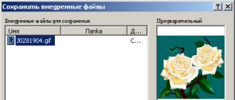
Solder the wires of the USB cable to the board, guided by the pinout of the cable, and not by the location on the oscilloscope diagram. On the diagram, the sequence of the veins is indicated arbitrarily. Also from the insignificant drawbacks, according to the reviews of those who used, after restarting Windows, we need to re-plug the oscilloscope into the USB port. Do not forget to remove the fuse - bit divider of the clock frequency by 8 CKDIV 8. This oscilloscope does not require any third-party drivers for its operation, and is defined as a Hid device, similar to a mouse or keyboard. When connected for the first time, the device will be identified as Easylogger. The following figure provides a list of the parts required for assembly.

There are 6 versions of the Usbscope program, the shell in which we actually observe the graph. The first three versions do not support 64-bit Windows operating systems. Starting with the fourth version of Usbscope, support is provided. For the program to work, Netframework must be installed on the computer. The source codes of the firmware and the source codes of the shell program were posted on the author's site, so there may be craftsmen who can supplement the software. What is the practical use of this oscilloscope, is it really just a toy? No, this device is used in a car manufacturer by home craftsmen, as a budget replacement for an expensive oscilloscope, for tuning car ignition systems, fuel consumption and similar needs.

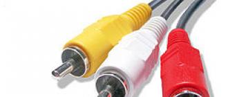
Apparently, the frequency of work in a car model is quite low, and this probe is minimally sufficient, at least for one-time work. To connect to the measured circuit, I soldered two probes, using for this, in order to reduce the level of interference, a shielded wire, tulips or an RCA connector. This allows easy connection and disconnection of probes from the oscilloscope.

- One of the wires - oscilloscope probes, ends for measurement with a probe from a multimeter for the signal core, and a crocodile for connecting to the ground.
- The second probe ends in crocodiles of different colors, both for the signal core and for the ground.
Conclusion: the assembly of this probe is more appropriate as a visual aid for studying the shape of low-frequency signals. For practical purposes, for example, for checking and adjusting switching power supplies, in particular for the operation of PWM controllers, this probe is unambiguous, since it cannot provide the required performance. Therefore, it cannot be a replacement, even for the simplest Soviet oscilloscope, and even for simple oscilloscopes with Ali Express.
You can download an archive with a circuit, firmware, a screen of fuses and an oscilloscope probe shell by following the link. All success, especially for - AKV.
Discuss the article USB PROBE-OSCILLOGRAPH
It is no secret that novice radio amateurs do not always have expensive measuring equipment on hand. For example, an oscilloscope, which even in the Chinese market, the cheapest model costs about several thousand.
Sometimes an oscilloscope is needed to repair various circuits, check amplifier distortions, adjust sound equipment, etc. Very often, a low-frequency oscilloscope is used to diagnose the operation of sensors in a car.
In this case, the simplest oscilloscope made from your personal computer will help you. No, your computer does not have to be disassembled or modified in any way. You just need to solder the prefix - divider for everything, and connect it to the PC via the audio input. And to display the signal, install special software. In a couple of tens of minutes, you will have your own oscilloscope, which may well be suitable for analyzing signals. By the way, you can use not only a stationary PC, but also a laptop or netbook.
Of course, such an oscilloscope is comparable with a real device, since it has a small frequency range, but it is a very useful thing in the household to see the amplifier outputs, various ripple of power supplies, etc.
Prefix diagram
Agree that the circuit is incredibly simple and does not take a lot of time to assemble it. This is a divider-limiter that will protect your computer's sound card from dangerous voltages that you might accidentally drop into the input. The divider can be 1, 10 and 100. The sensitivity of the entire circuit is regulated by a variable resistor. The set-top box is connected to the line-in of the PC sound card.We collect the prefix
You can take a battery box like me or another plastic case.
Software
The "oscilloscope" program will visualize the signal applied to the input of the sound card. I will offer you two options for downloading:1) A simple program without installation with a Russian interface, download it.
(Downloads: 9807)

2) And the second is with the installation, you can download it -.

Which one to use is up to you. Take and install both, and then choose.
If you already have a microphone installed, then after installing and launching the program, you can already observe the sound waves that enter the microphone. It means everything is OK.
For the set-top box, no more drivers are required.
We connect the set-top box to the line or microphone input of the sound card and use it for health.

If you have never had any experience with an oscilloscope in your life, then I sincerely recommend that you repeat this homemade product and work with such a virtual instrument. The experience is very valuable and interesting.
An oscilloscope is a portable device designed for testing microcircuits. Additionally, many models are suitable for industrial control and can be used for various measurements. It is impossible to make an oscilloscope with your own hands without a zener diode, which is its main element. This part is installed in a device of various powers.
Additionally, devices, depending on the modification, may include capacitors, resistors and diodes. The main parameters of the model include the number of channels. Depending on this indicator, the limiting bandwidth changes. Also, when assembling an oscilloscope, consider the sampling rate and memory depth. In order to analyze the received data, the device is connected to a personal computer.
Simple oscilloscope circuit
A simple oscilloscope circuit includes a 5 V zener diode. Its bandwidth depends on the types of resistors that are installed on the microcircuit. Capacitors are used to increase the vibration amplitude. You can make a probe for an oscilloscope with your own hands from any conductor. In this case, the port is selected separately in the store. Resistors of the first group must withstand the minimum resistance in the circuit at a level of 2 ohms. Moreover, the elements of the second group should be more powerful. It should also be noted that there are diodes on the circuit. In some cases, they line up as bridges.

Single channel model
It is possible to make a single-channel digital oscilloscope with your own hands only using a 5 V zener diode. In this case, more powerful modifications are unacceptable in this case. This is due to the fact that an increased limit voltage in the circuit leads to an increase in the sampling rate. As a result, the resistors in the device fail. Capacitors for the system are selected only of the capacitive type.
The minimum resistor must keep the resistance at 4 ohms. If we consider the elements of the second group, then the transmission parameter in this case should be 10 Hz. In order to raise it to the desired level, various types of regulators are used. Some experts recommend using orthogonal resistors for single-channel oscilloscopes.
In this case, it should be noted that they raise the sampling rate indicator rather quickly. However, negative aspects in such a situation are still present, and they should be taken into account. First of all, it is important to note the sharp excitation of oscillations. As a result, the asymmetry of the signals increases. Additionally, there are problems with the sensitivity of the device. Ultimately, the accuracy of the readings may not be the best.

Dual channel devices
It is quite difficult to make a two-channel oscilloscope with your own hands (the diagram is shown below). First of all, it should be noted that zener diodes in this case are suitable for both 5 V and 10 V. In this case, capacitors for the system must be used only of a closed type.
Due to this, the bandwidth of the device can be increased to 9 Hz. Resistors for the model, as a rule, are of the orthogonal type. In this case, they stabilize the signal transmission process. To perform the functions of addition, microcircuits are selected mainly of the MMK20 series. You can make a divider for an oscilloscope with your own hands from a conventional modulator. It's not particularly difficult.

Multichannel modifications
In order to assemble a USB oscilloscope with your own hands (the diagram is shown below), a Zener diode will need a rather powerful one. The problem in this case is to increase the bandwidth of the circuit. In some situations, the resistors may malfunction due to a change in the limiting frequency. In order to solve this problem, many people use auxiliary divisors. These devices do a lot to help raise the voltage limit.
The divider can be made using a modulator. The capacitors in the system must be installed only near the zener diode. Analog resistors are used to increase the bandwidth. The negative resistance parameter on average fluctuates around 3 ohms. The blocking range depends solely on the power of the zener diode. If the limiting frequency drops sharply when the device is turned on, then the capacitors must be replaced with more powerful ones. Some experts in this case advise to install diode bridges. However, it is important to understand that the sensitivity of the system in this situation deteriorates significantly.
Additionally, you need to make a probe for the device. In order for the oscilloscope not to conflict with a personal computer, it is more expedient to use an MMP20 type microcircuit. You can make a probe from any conductor. In the end, a person will only have to acquire a port for him. Then, using a soldering iron, the above elements can be connected.

Assembling a 5V device
At 5 V, a do-it-yourself oscilloscope-set-top box is made only using an MMP20 type microcircuit. It is suitable for both conventional and high-power resistors. The maximum resistance in the circuit should be 7 ohms. In this case, the bandwidth depends on the signal transmission rate. Dividers for devices can be used in a variety of ways. Today, static analogs are considered to be more common. The bandwidth in such a situation will be at around 5 Hz. To increase it, you need to use tetrodes.
They are selected in the store, based on the parameter of the limiting frequency. To increase the amplitude of the reverse voltage, many experts advise installing only self-regulating resistors. In this case, the signal transmission rate will be quite high. At the end of the work, you need to make a probe to connect the circuit to a personal computer.
10 V oscilloscopes
A do-it-yourself oscilloscope is made with a zener diode, as well as closed-type resistors. If we consider the parameters of the device, then the vertical sensitivity indicator should be at the level of 2 mV. Additionally, the bandwidth should be calculated. For this, the capacitance of the capacitors is taken and correlated with the limiting resistance of the system. The resistors for the device are most suitable for the field type. To minimize the sampling rate, many experts advise using only 2 V diodes. Due to this, a high signal transmission rate can be achieved. In order for the tracking function to be performed rather quickly, microcircuits are installed of the MMP20 type.
If you plan storage and playback modes, then you need to use a different type. Cursor measurements in this case will be unavailable. The main problem with these oscilloscopes can be considered a sharp drop in the limiting frequency. This is due, as a rule, to fast data scan. The task can be solved only with the use of a high-quality divider. That being said, many also rely on a zener diode. The divider can be made using a conventional modulator.

How to make a 15V model?
The oscilloscope is assembled with your own hands using linear resistors. They are able to withstand the ultimate resistance at the level of 5 mm. Due to this, there is not much pressure on the Zener diode. Additionally, you should take care of the selection of capacitors for the device. For this purpose, it is necessary to make measurements of the threshold voltage. Specialists use a tester for this.
If you use tuning resistors for the oscilloscope, you may encounter increased vertical sensitivity. Thus, the data obtained as a result of testing may be incorrect. Considering all of the above, only linear analogs should be used. Additionally, you should take care of installing a port that is connected in the microcircuit through a probe. In this case, it is more expedient to install the divider through the bus. So that the vibration amplitude is not too large, many advise using vacuum-type diodes.
Using resistors of the PPR1 series
Making a USB oscilloscope with your own hands with these resistors is not an easy task. In this case, it is necessary first of all to evaluate the capacitance of the capacitors. In order to keep the voltage limit below 3 V, it is important to use no more than two diodes. Additionally, you should remember about the nominal frequency parameter. On average, this figure is 3 Hz. Orthogonal resistors are not suitable for such an oscilloscope unambiguously. Construction changes can only be made using a divider. At the end of the work, you need to deal with directly installing the port.
Models with PPR3 resistors
You can make a USB oscilloscope with your own hands using only grid capacitors. Their peculiarity lies in the fact that the level of negative resistance in the circuit can reach 4 ohms. A wide variety of microcircuits are suitable for such oscilloscopes. If we take the standard version of the MMP20 type, then it is necessary to provide at least three capacitors in the system.
Additionally, it is important to pay attention to the density of the diodes. In some cases, the bandwidth factor depends on it. To stabilize the fission process, experts advise to carefully check the conductivity of the resistors before turning on the device. Finally, the regulator is connected directly to the system.

Oscillation suppression devices
Oscilloscopes with a vibration suppression unit are rarely used these days. They are most suitable for testing electrical appliances. Additionally, it should be noted their high vertical sensitivity. In this case, the parameter of the limiting frequency in the circuit should not exceed 4 Hz. Due to this, the Zener diode does not overheat much during operation.
A do-it-yourself oscilloscope is made using a grid-type microcircuit. In this case, it is necessary at the very beginning to determine the types of diodes. Many in this situation are advised to use only analog types. However, in this case, the signal transmission rate can be significantly reduced.