After taking notes on choosing a TV, I decided to arrange a small educational program on the entrances and exits.
The antenna jack of the TV is familiar to everyone.
Any TV has a simple composite video input and analog audio inputs (tulips).
The picture quality for this input is the lowest, only low-resolution video can be transmitted.
The S-Video connector also transfers low-definition video.
The picture quality is slightly better, but almost insignificant.
The 21-pin SCART connector can contain inputs and outputs of composite video, analog audio, S-Video and RGB inputs at once, providing the maximum quality of a low-resolution analog signal.
In different TVs, only some of the signals listed above can be output to the SCART connector.
Component connectors also provide the best analogue signal quality and also handle high definition video up to 720p.
The sound is transmitted by two separate tulips. There are 5 connectors in total.
VGA connector (aka D-SUB). 15-pin connector for connecting a computer.
The TV works like a standard monitor. The sound is also transmitted through two separate tulips. Unfortunately, in new TV models the VGA connector is often absent, and if a stationary computer (possibly after revision and installation of a video card) can be connected to a TV via HDMI, then most laptops, alas, do not.
HDMI connector. Digital input, which, unlike all previous ones, transmits not only video, up to the maximum FullHD resolution, but also digital sound.
HDMI is the most modern and standard way of connecting.
When connecting a TV to a computer via HDMI or VGA, it is desirable that the TV show "point to point", that is, if the FullHD image, 1920 pixels wide, output by the computer should exactly correspond to 1920 pixels displayed by the TV. Often on TVs, the Overscan mode is turned on by default, which slightly enlarges the picture and does not allow showing point to point. It needs to be found and disabled. You can check the correctness of the display by carefully looking at the computer desktop displayed on the TV. All letters should be very clear with no smudged edges. Sometimes there are LCD TVs with a screen resolution that does not allow you to display the picture point-to-point at all. HD Ready plasmas usually have a resolution of 1024x768 with a 16: 9 screen format, with each dot not square, but rectangular. At the same time, if you set the resolution to 1024x768 on your computer, a big problem arises - the image is stretched, because the computer thinks that the points are square. For the correct viewing of films in this mode, you can use the GOM Player and KM Player, which have options for displaying images on a wide TV. With the display of photos, everything is worse - I still could not find a program that would correctly display photos on a monitor with rectangular pixels.
Headphone jack. Surprisingly, not all TVs have it.
Sound outputs.
An output that can be connected to an external amplifier for watching TV programs with better sound quality. There are linear (unregulated) and regulated outputs. The signal level at the adjustable output will depend on the volume setting on the TV.
Digital audio output (usually optical). Allows you to connect your TV to an AV receiver with a digital audio decoder.
USB connector - allows you to connect USB devices (flash drives, hard drives, keyboards, Wi-Fi adapters) to the TV.
The functionality of the USB connector on each TV is different. Some TVs have a built-in player that plays almost all video formats.
Slot for SD memory cards.
Depending on the model, it allows you to watch photos and videos on the TV. Videos are usually only selected formats.
Local area network (LAN) connector.
Allows you to connect your TV to your home network and the Internet. The functionality is also different for all models with such a connector. Some can stream videos from YouTube, surf the Internet and even allow you to make video calls over Skype, some can play videos over the network from a computer or home DLNA server.
In addition, TVs have completely exotic connectors. For example, my LG 42PC1RR plasma has an RS-232 connector that allows you to control the plasma from a computer instead of a remote control, but this functionality is unlikely to ever be needed in everyday life.
Composite video
Composite video signal of "color stripes" on the oscilloscope screen. The luminance signal, subcarrier and sync signal are visible
Composite video, composite video- full analog television color video signal transmitted over one communication line separately from sound. Unlike component video, in which the individual components of the video signal - luminance and chrominance - are transmitted over separate lines, composite video requires a single communication line and, together with sound, makes up a complete television signal, ready for broadcast.
Composite signal composition
A full color video signal contains three main components: a luminance signal, a subcarrier modulated with a chroma signal, and a sync signal consisting of horizontal and vertical sync pulses, blanking and equalizing pulses. The subcarrier also contains color bursts. Therefore, in foreign sources, composite video is often referred to as CVBS, which stands for “Color, Video, Blank and Sync”.
Video recording
Also, the term is used in relation to analog video recording formats. Most common video recording formats are considered composite, since they use one group of video heads and a signal processing path to record / reproduce all components of the video signal. However, in most composite formats, the luminance signal and subcarrier are separated to carry the spectrum of the latter, so that its frequencies fall within the recorded range. When played back, the signal is split again for separate luminance and subcarrier processing, and is combined again at the output. This leads to significant quality losses during repeated re-recording, therefore, in broadcast practice, component formats are used, such as Betacam or S-VHS, which use separate video heads and processing paths to record / reproduce individual components of the video signal. Component formats provide higher image quality and allow more rewrites due to the lack of crosstalk inherent in composite formats.
disadvantages
The use of a composite video signal for TV transmission makes it possible to dispense with a single communication channel and to narrow the frequency band occupied by each TV channel. However, the joint transmission of luminance and chrominance signals requires their separation in the receiving device, in which the appearance of mutual interference that degrades the image quality is inevitable. Therefore, most professional studio equipment uses separate transmission of luminance and chrominance using component interfaces such as S-Video. The development of consumer video technology and the increased demands on video quality have led to the proliferation of component transmission lines between consumer devices. The European SCART interface allows the transmission of a component video signal, just like S-Video, which has become widespread in home video equipment and computers.
Connection types
Composite BNC

RCA connectors for video and stereo sound. Yellow for video, white for monaural or left channel for stereo two-channel audio, red for right channel for stereo two-channel audio
The main type of connection for transferring composite video signals between professional image processing and recording devices is a coaxial cable with connectors of the type BNC... In household devices, for the transmission of a composite video signal CVBS, as a rule, a cable with standard RCA connectors, commonly called "tulip" (bells), is used. Household composite video cords are rarely coaxial. In this case, the sound is transmitted over a separate wire with similar connectors.
In consumer video technology, the transmission of composite video and audio over two separate wires was often referred to as a "low frequency connection" and was an alternative to "high frequency" connection, in which the entire television signal was transmitted over an antenna coaxial cable using one of the standard broadcast channels. This connection is often used in consumer VCRs to transfer images and sound to a TV set.
see also
Wikimedia Foundation. 2010.
See what "Composite Video" is in other dictionaries:
This is a list of video connectors and corresponding video signal standards. Contents 1 By signal standard 2 Physical connectors 3 P ... Wikipedia
- (from English Video capture video capture) the process of converting a video signal from an external source into a digital video stream using a personal computer and recording it into a video file for its subsequent processing, storage, or ... ... Wikipedia
Modern computers are highly capable of working with video, and their owners often watch movies on the monitor screen. And with the advent of barebone multimedia platforms aimed at using as a home media center, the interest in connecting audio and video equipment is only increasing.
It is much more convenient and practical to watch video on a large TV screen, especially since almost all modern video cards are equipped with a TV output.
The need to connect a TV to a computer also arises when editing amateur video. As you can easily see in practice, the picture and sound on a computer are significantly different from those that you will later see and hear on TV. Therefore, all video editors allow you to view preliminary editing results on a television receiver directly from the working scale even before creating a movie. Experienced video enthusiasts constantly monitor the picture and sound by displaying them on a television screen, not on a computer monitor.
Topics such as setting up video cards, choosing an image standard, as well as comparing the quality of video outputs of video cards from different manufacturers and solving the problems that arise are beyond the scope of this article - here we will consider only the following questions: what connectors can be found on a TV and on a video card, how they agree with each other and what are the ways to connect a computer to a TV.
Display interfaces
Classic analog interface (VGA)
Computers have been using the 15-pin analog D-Sub HD15 (Mini-D-Sub) interface for quite some time, which is traditionally called the VGA interface. The VGA interface carries red, green, and blue (RGB) signals, as well as horizontal scan (H-Sync) and vertical sync (V-Sync) information.
All modern video cards have such an interface or provide it with an adapter from the universal combined DVI-I (DVI-integrated) interface.
Thus, both digital and analog monitors can be connected to the DVI-I connector. A DVI-I to VGA adapter is usually included with many graphics cards and allows you to connect older monitors with a 15-pin D-Sub (VGA) plug.

Please note that not every DVI interface supports analog VGA signals, which can be obtained through such adapters. Some video cards have a DVI-D digital interface to which you can connect only digital monitors. Visually, this interface differs from DVD-I by the absence of four holes (pins) around the horizontal slot (compare the right side of the white DVI connectors).

Often modern graphics cards are equipped with two DVI outputs, in which case they are usually universal - DVI-I. Such a video card can simultaneously work with any monitors, both analog and digital in any set.

DVI digital interface
The DVI interface (TDMS) was designed primarily for digital monitors that do not require the graphics card to convert digital signals to analog signals.

But since the transition from analog to digital displays is slow, graphics hardware designers tend to use these technologies in parallel. In addition, modern video cards can work with two monitors at the same time.
The universal DVI-I interface allows for both digital and analogue connections, while DVI-D is digital only. However, the DVI-D interface is quite rare today and is usually used only in cheap video adapters.
In addition, digital DVI connectors (both DVI-I and DVI-D) have two varieties - Single Link and Dual Link, which differ in the number of contacts (in Dual Link, all 24 digital contacts are involved, and in Single Link - only 18 ). Single Link is suitable for use in devices with resolutions up to 1920x1080 (full HDTV resolution), for b O higher resolutions already require Dual Link, which allows you to double the number of displayed pixels.
HDMI digital interface
The digital multimedia interface HDMI (High Definition Multimedia Interface) was developed jointly by a number of large companies - Hitachi, Panasonic, Philips, Sony, etc. The 19-pin version of HDMI is widely used today to transmit high-definition television (HDTV) signals with a resolution of up to 1920x1080 (1080i ). Higher definition video requires 29-pin Type B connectors. In addition, HDMI can provide up to eight channels of 24-bit 192 kHz audio and has built-in Digital Rights Management (DRM) copyright protection.

HDMI is relatively new, but it has quite a few competitors in the computer sector, both from the traditional DVI interface and from newer and more advanced interfaces such as UDI or DisplayPort. However, products with HDMI ports are steadily moving into the market, as modern consumer video equipment is increasingly equipped with HDMI connectors. Thus, the growing popularity of multimedia computing platforms will stimulate the emergence of graphics and motherboards with HDMI ports, even though computer manufacturers have to buy a rather expensive license to use this standard and also pay some flat royalties from each product sold with an HDMI interface. ...
License fees also increase the cost of products with HDMI ports for the end manufacturer - for example, a video card with an HDMI port will cost about $ 10 more. In addition, it is unlikely that an expensive HDMI cable ($ 10-30) will be included in the package, so you will have to purchase it separately. However, there is hope that with the growing popularity of the HDMI interface, the size of such a markup will gradually decrease.
HDMI uses the same TDMS signal technology as DVI-D, so inexpensive adapters are available for these interfaces.

And while the HDMI interface has not yet replaced DVI, such adapters can be used to connect video equipment via the DVI interface. Please note that HDMI cables cannot be longer than 15m.
New UDI interface
At the beginning of this year, Intel announced a new digital interface UDI (Unified Display Interface) for connecting digital monitors to a computer. So far, Intel has just announced the development of a new type of connection, but in the near future it plans to completely abandon the old analog VGA interface and connect computers to display devices through a new digital interface UDI, recently developed by the engineers of this company.

The creation of the new interface is due to the fact that both the analog VGA interface and even the digital DVI interface, in the opinion of Intel representatives, are hopelessly outdated today. In addition, these interfaces do not support the latest content protection systems found in next generation digital media such as HD-DVD and Blu-ray.
Thus, UDI is almost analogous to the HDMI interface used to connect computers to modern HD TVs. The main (and perhaps the only) difference between UDI and HDMI will be the lack of an audio channel, that is, UDI will transmit only video and is entirely designed to work with computer monitors, not HD TVs. In addition, Intel appears to be reluctant to pay licensing fees for every HDMI device it produces, so UDI is a good alternative for companies looking to reduce the cost of their products.
The new interface is fully compatible with HDMI, and will also support all currently known content protection systems, which will allow the smooth playback of new media equipped with copy protection.
New DisplayPort interface
Another new video interface, DisplayPort, was recently approved by the Video Electronics Standards Association (VESA) companies.
The open DisplayPort standard has been developed by a number of large companies, including ATI Technologies, Dell, Hewlett-Packard, nVidia, Royal Philips Electronics, and Samsung Electronics. It is assumed that in the future, DisplayPort will become a universal digital interface that allows you to connect displays of various types (plasma, liquid crystal, CRT monitors, etc.) to household devices and computer equipment.

The DisplayPort 1.0 specification provides for the possibility of simultaneous transmission of both video signal and audio streaming (in this sense, the new interface is completely similar to HDMI). Note that the DisplayPort maximum throughput is 10.8 Gbps, with a relatively thin four-conductor interconnect cable used for transmission.
Another feature of DisplayPort is its support for content protection functions (similar to HDMI and UDI). Built-in security controls allow the content of a document or video file to be displayed only on a limited number of “authorized” devices, which theoretically reduces the likelihood of illegal copying of copyrighted material. Finally, the new standard connectors are thinner than today's DVI and D-Sub connectors. This will allow DisplayPorts to be used in small form factor equipment and easily build multi-channel devices.
DisplayPort support has already been announced by Dell, HP and Lenovo. Most likely, the first devices equipped with new video interfaces will appear before the end of this year.
Video connector on graphics card
On modern video cards, in addition to connectors for connecting monitors (analog - D-Sub or digital - DVI), there is a composite video output ("tulip"), or a 4-pin S-Video output, or a 7-pin combined video output ( both S-Video and composite inputs and outputs).

In the case of S-Video, the situation is simple - there are S-Video cables or adapters for other SCART connectors on sale.
However, when a non-standard 7-pin connector is found on video cards, then in this case it is better to keep the adapter that comes with the video card, because there are several wiring standards for such a cable.

Composite video (RCA)
The so-called composite video output has long been widely used to connect consumer audio and video equipment. The connector for this signal is usually referred to as RCA (Radio Corporation of America), and popularly referred to as "tulip" or VHS connector. Please note that not only composite video or audio, but also many other signals such as component video or high definition television (HDTV) can be transmitted with such plugs in video equipment. Typically, tulip plugs are color-coded to help users navigate through the bundle of wires. Common meanings of colors are given in table. 1.
Table 1
|
Usage |
Signal type |
|
|
White or black |
Sound, left channel |
Analog |
|
Sound, right channel |
Analog |
|
|
Video, composite signal |
Analog |
|
|
Luminance component signal (Luminance, Luma, Y) |
Analog |
|
|
Chrominance, Chroma, Cb / Pb Component Signal |
Analog |
|
|
Chrominance Component (Chrominance, Chroma, Cr / Pr) |
Analog |
|
|
Orange / yellow |
SPDIF digital audio |
Digital |

Composite wires can be long enough (simple adapters can be used to extend wires).

However, the use of low quality connections and sloppy "tulip" switching is gradually becoming a thing of the past. In addition, cheap RCA connectors on equipment often break. Today, other types of switching are increasingly used on digital audio and video equipment, and even when transmitting analog signals, it is more convenient to use SCART.
S-Video
Often the video card and TV have a four-pin S-Video connector (Y / C, Hosiden), which is used to transmit video signals of higher quality than composite. The fact is that the S-Video standard uses different lines for transmitting luminance (the luminance and data synchronization signal is denoted by the letter Y) and color (the chroma signal is denoted by the letter C). Separation of luminance and color signals allows to achieve better picture quality compared to the composite RCA interface ("tulip"). Higher quality analog video can only be achieved with completely separate RGB or component interfaces. To receive a composite signal from S-Video, a simple S-Video to RCA adapter is used.

If you do not have such an adapter, then you can make it yourself. However, there are two options for outputting a composite signal from a video card equipped with an S-Video interface, and the choice depends on the type of your video card. Some cards can switch output modes and send a simple composite signal to the S-Video output. In the mode of supplying such a signal to S-Video, you just need to connect the pins to which the composite signal is supplied with the corresponding tulip outputs.

The RCA cable routing is simple: the center conductor carries the video signal, and the outer braid is the ground.
The S-Video wiring is as follows:
- GND - "ground" for the Y-signal;
- GND - "ground" for the C-signal;
- Y - luminance signal;
- C - chrominance signal (contains both color difference).
If the S-Video-out can work in the composite signal supply mode, then the second pin of its connector is connected to ground, and the fourth - the signal. On a collapsible S-Video plug, which is required to make an adapter, the contacts are usually numbered. Jack and plug connectors are numbered mirrored.
If the video card does not have a composite signal output mode, then to obtain it, you will have to mix the chroma and luminance signal from the S-Video signal through a 470 pF capacitor. The signal received in this way is fed to the central core, and the "ground" from the second contact is fed to the braid of the composite cord.
SCART
SCART is the most interesting combined analog interface and is widely used in Europe and Asia. Its name comes from the French abbreviation proposed in 1983 by the Union of Developers of Radio and Television Equipment of France (Syndicat des Constructeurs d'Appareils, Radiorecepteurs et Televiseurs, SCART). This interface combines analog video (composite, S-Video, and RGB), stereo audio, and control signals. Today, every TV or VCR produced in Europe is equipped with at least one SCART socket.

For the transmission of simple analog signals (composite and S-Video), there are many different SCART adapters on the market. This interface is convenient not only because everything is connected using only one cable, but also because it allows you to connect a high-quality RGB video source to a TV without intermediate encoding into composite or S-Video signals and get the best image quality on a consumer TV screen. (the picture and sound quality when fed through SCART is noticeably superior to that of any other analog connections). This possibility, however, is not realized in all VCRs and TVs.
In addition, the developers have incorporated additional capabilities into the SCART interface, having reserved several contacts for the future. And since the SCART interface became a standard in European countries, it has acquired several new features. For example, with the help of some signals on pin 8, you can control the TV modes via SCART (switch it to “monitor” mode and vice versa), switch the TV to work with RGB signals (pin 16), etc. Pins 10 and 12 are for digital data transmission via SCART, which makes the number of commands practically unlimited. There are several well-known SCART communication systems: Megalogic, used by Grundig; Easy Link from Philips; SmartLink from Sony. True, their use is limited to communication between the TV and the VCR of these companies.
By the way, the standard provides for four types of SCART cables: type U - universal, providing all connections, V - without sound signals, C - without RGB signals, A - without video and RGB signals. Unfortunately, modern component modes (Y, Cb / Pb, Cr / Pr) are not supported in the SCART standard. However, some manufacturers of DVD-players and large-format TVs build in the ability to transmit via SCART and component video, which is transmitted through the pins used in the standard for RGB-signal (however, this possibility is practically the same from connecting via RGB).
Various adapters are available for connecting composite or S-Video sources to SCART. Many of them are universal (bi-directional) with an I / O switch.

There are also simple unidirectional adapters, mono or stereo adapters, and connectors for switching control. In the case when it is necessary to connect two at once to one device, you can use a SCART splitter in two or three directions. Those who are not satisfied with the proposed options or who are not available can make their own in accordance with the pin assignments in SCART, given in table. 2.
The pin numbering is usually indicated on the connector:

Of course, computers do not use a SCART connector, however, knowing its specification, you can always make an appropriate adapter for using an analog computer monitor as a receiver of a video signal from a tape recorder or, conversely, for supplying a video signal from a computer to a TV equipped with a SCART connector.
For example, in order to input or output a composite signal from a SCART connector, you need to take a coaxial cable with a characteristic impedance of 75 ohms and distribute the outer braid (ground) and the inner core (composite signal) on the SCART connector.
Video signal output from computer to TV (TV-OUT):
- the composite signal is fed to pin 20 of the SCART connector;
To input video signal from a VCR to a computer (TV-IN):
- composite signal - to the 19th pin of the SCART connector;
- "Ground" - to the 17th pin of the SCART connector.
The correspondence of contacts in the manufacture of an adapter for S-Video is also indicated in table. 2.
Video signal output from a computer to a TV via S-Video (TV-OUT):
- 3rd S-Video pin - 20th SCART pin;
Video signal input from a VCR to a computer via S-Video (TV-IN):
- 1st S-Video pin - 17th SCART pin;
- 2nd S-Video pin - 13th SCART pin;
- 3rd S-Video pin - 19th SCART pin;
- 4th S-Video pin - 15th SCART pin.
To connect a computer to a TV via RGB, it is necessary that the computer outputs an RGB signal in a form that the TV can understand. Sometimes the RGB signal is fed through a dedicated 7-, 8-, or 9-pin composite video output. In this case, the video card settings should be able to switch the video output to RGB mode. If the video output on a video card has seven pins (such a plug is called a mini-DIN 7-pin), then in normal mode the S-Video signal is fed to exactly the same pins as in a regular four-pin S-Video connector. And in RGB mode, signals can be distributed to contacts in different ways, depending on the manufacturer of the video card.
As an example, we can give the correspondence of the pins of one of these 7-pin connectors with SCART (this wiring is used on some video cards based on the NVIDIA chip, but on your video card it may be different):
- 1st mini-DIN 7-pin contact (GND, "ground") - 17th SCART contact;
- 2nd pin mini-DIN 7-pin (Green, green) - 11th pin SCART;
- 3rd pin mini-DIN 7-pin (Sync, sweep) - 20th pin SCART;
- 4th pin mini-DIN 7-pin (Blue, blue) - 7th pin SCART;
- 5th pin mini-DIN 7-pin (GND, "ground") - 17th pin SCART;
- 6th mini-DIN 7-pin (Red, red) - 15th SCART;
- 7th pin mini-DIN 7-pin (+3 V RGB mode control) - 16th pin SCART.
All types of adapters require the use of high quality 75 Ohm cables.
There is no video connector on the graphics card
If your video card does not have a TV output, then, in principle, a TV can be connected to a regular VGA connector. However, in this case, an electrical signal matching circuit will be required (in the general case, however, it is not complicated). There are special devices on the market that convert a regular computer VGA signal to RGB and a scan (sync) signal for a TV. Such a device connects to the VGA cable between the computer and the monitor and duplicates the signal that goes through the VGA output.
In principle, such a device can be made independently. The correspondence between VGA and SCART signals will be as follows:
- VGA SCART PIN SCART Description;
- VGA RED - to the 15th SCART pin;
- VGA GREEN - to the 11th SCART pin;
- VGA BLUE - to the 7th SCART pin;
- VGA RGB GROUND - on the 13th, or 9th, or 5th SCART pin;
- VGA HSYNC & VSYNC - on the 16th and 20th SCART pins.
You will also need to apply + 1-3 V to the 16th SCART pin and 12V to the 8th SCART pin to switch to AV mode with an aspect ratio of 4: 3.
However, a direct connection will most likely not work and for synchronization you will have to make an electrical circuit, as shown at http://www.tkk.fi/Misc/Electronics/circuits/vga2tv/circuit.html or http: //www.e.kth .se / ~ pontusf / index2.html.
Connecting various peripheral devices to electronic equipment most often requires wires. Depending on whether you're connecting a TV to a VCR or a monitor to a computer, it's important to consider the type of wires. Digital technology is starting to dominate analogue more and more, but, in any case, you need to be able to understand the main cable formats used. We'll tell you about 13 different cables (video, audio, and computer-specific) in enough detail so that you don't have any confusion in the future.
In addition, we recommend that you read the article " Encyclopedia of Computer Interfaces: The THG Guide ".
Composite cable
Click on the picture to enlarge.
Let's start with the video cables. First, consider a Composite Video cable, sometimes referred to as an RCA cable, or simply "cinch". This cable has a yellow connector and works with analog composite video signal. To be honest, this is the worst option in its category. All low-resolution signals pass through the composite cable in a mixed form, combining the luminance and chrominance signals. Typically, such a composite video cable is accompanied by two other connectors: red and white. They are used to transmit stereo sound. If possible, instead of a composite cable, use a separate channel cable such as S-Video, RGB, or even YUV.
S-Video
Click on the picture to enlarge.
S-Video cable is also known as Y / C cable. These two letters indicate that the video signal in such a cable is split into two separate components that are transmitted along its own wire: luminance and chrominance. Unlike composite video cable, S-Video allows you to get a much clearer picture. In addition, all elements of the image are transmitted at the same time. The S-Video cable is used by video cards, video cards, camcorders, and even with S-VHS VCRs. Like composite video, S-Video only transmits the image. A separate cable is required for audio transmission.
Component cables YUV, YPrPb and YCrCb
Click on the picture to enlarge.
In the case of YUV, YPrPb and YCrCb formats, you get completely separate signals. Component cables are made up of three wires, one for brightness (Y) and the other two for color. Component cables are more or less consistent with the high-end version of S-Video, but their quality is close to DVI or HDMI. Colors are rendered incredibly accurate, and the overall picture is more in line with what you should see on a TV screen than other analog cables. The YUV cable is capable of transmitting high definition video, albeit in analog form.
VGA
Click on the picture to enlarge.
The VGA analog interface was created in the late 1980s through the efforts of IBM and remains the standard connector for connecting a monitor to a computer to this day. However, it is now being replaced by the digital DVI interface. VGA has 15 pins arranged in three rows, each of which is responsible for three separate channels: red, blue and green. There are many versions of VGA depending on the resolution: QVGA is 320 x 240, XGA is 1024 x 768, and QXGA is 2048 x 1536. For wide screens, this standard is simply referred to as WVGA ("W" stands for "wide"). Mini-VGA is used for some laptops. Although almost all video cards on the market are equipped with DVI, you will find many displays that connect to VGA via VGA / DVI adapters.
DVI-A / D / I
Click on the picture to enlarge.
This cable is a replacement for VGA. It allows you to transfer a digital signal between the video card and the display. Pay attention to the intricacies of this standard: in fact, there are three types of DVI. DVI-A carries only analog signal (for VGA compatibility), while DVI-D can only carry digital signal. DVI-I, on the other hand, can handle both types of signals, but not simultaneously. Therefore, it cannot be used with CRT monitors. But it's okay, because there is DVI-A / DVI-I. Most video cards are equipped with DVI-I outputs, which are suitable for connecting a CRT monitor to a computer using an adapter. As for laptops, mini-DVI is gradually replacing mini-VGA. At the same time, if your monitor has a large "native" resolution (more than 3 million pixels), then you need to use dual-link Dual-Link DVI.
|
|||
|
| |||
I am glad to have new communication with my readers and today we will talk about the good old RCA connector. For some it will be nostalgia for the first experience of using audio-video equipment. Well, to the younger generation, I will tell what kind of an unprecedented wonder that is still found on some devices.
To begin with, according to tradition, a small excursion into the history of radio electronics.
Back in 1940, it became necessary to connect phonographs to amplifiers, and the so far known Radio Corporation of America (RCA) proposed using a connector in the form of a shielded axial contact. Which later inherited the same name and gained immense popularity.
By the way, the principle itself, when one of the contacts plays the role of external protection, has been further developed and is successfully used in more modern connectors.
The subject of the conversation
Now let's take a closer look at the RCA connector and figure out what it is. To begin with, let's pay attention to the element that is inserted (therefore called "dad") and placed on the cable itself. Since a two-wire wire is used, the connector, respectively, consists of 2 contacts. The first (main) is a pin 15 mm long and 3.2 mm in diameter with a rounded head (for easy entry into the socket).
It is located inside a cylindrical shield contact with a diameter of 8 mm, and protrudes from it by 9 mm. The socket, respectively referred to as "mother", is made in the form of a sleeve. Its outer part is a shield contact, and inside there is a hole for a pin to enter.

In both halves of the connector, the space between the center and outer contact is filled with a dielectric material. In inexpensive models, ordinary plastic (polyethylene) is used for this purpose, and in more expensive variations, textolite washers. Well, in the most trump version - Teflon or ceramics.

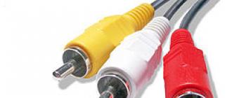
We found out the physics of the process. Let's move on to the lyrically floral part of our review. This is not just a literary turnover, but an allusion to the second name of the RCA connector, which is commonly called a tulip. Very accurate figurative hit because three connectors are usually used: one for video signal, the other two for stereo sound. To distinguish them, the plastic shell of each connector has its own strictly defined color:
- Yellow - video;
- Red - right audio channel;
- White - left audio channel;
Take a cable in your hand, at the end of which there are 3 RCA plugs. Doesn't it look very much like a bouquet of tulips?
Until now, no one has argued with this.

For sound 2 a for video 1 plug
You can ask a logical question. How is it that there are as many as 2 connectors for sound, and only one for a technologically more complex video?
The fact is that a composite signal passes through the “yellow tulip”, which combines all the information:
- Brightness;
- Chromaticity;
- Extinguishing;
- Line, frame and color sync;
But there are also blue and green tulips. These are already component plugs for the transmission of individual color video streams.

Popularity that drives excellence
Since we have moved on to such complex technical details, it is time to talk about the technical aspects of using the RCA connector.
Its main purpose is to transmit analog audio-video signal. And he coped with this task brilliantly before the advent of digital standards. At one time, tulips were the only way to connect TVs to VCRs or DVD players.
Convenient connection has been actively used in audio equipment and amplifiers. Hardware manufacturers even made such outputs on a sound card.

And the craftsmen performed a special RCA wiring for connecting TVs as a monitor to a PC.
Over time, many industrial cables and adapters have appeared that allow you to connect TV to more modern gadgets. For example, using an RCA-mini jack cable, it was possible to send content from some smartphones.

Now the RCA connector can still be found on modern TVs or projectors, designed to be connected to some video playback devices. However, on screens with a maximum resolution of 4K and higher, transmitting an analog signal via RCA looks meaningless. Why?
Yes, because - that the usual composite (rca) is able to output a maximum of Full HD.
And therefore, manufacturers are abandoning it in favor of more modern information transfer standards.
As you understand, my dear readers, the era of RCA connectors is coming to an end. But it is still necessary to pay tribute to them. I hope you have more modern technology at your disposal. And the one with tulips will simply remind of the rapid progress of technology.
On this I say goodbye and promise that we will continue talking about different connectors.
See you soon.