The idea of creating a telegraphic manipulator from paper clips is not new. I, in particular, got it from here: http://www.us7ign.com/?p=631
Elementary, as you can see, even a child can handle it.
But when I found a suitable piece of PCB, bent a couple of paper clips and bolted it all together, it became clear that the structure was too light.

For normal operation, you will either need to attach it rigidly to the table, or somehow make it heavier. I chose the second option, plus I bought a set of self-adhesive rubber feet for radio equipment.
To make it heavier, I decided to make a lead base. To do this, he blinded a model of the base from plasticine, put it in the freezer for a couple of hours (for hardness). In a ceramic bowl, he spread the finishing plaster putty. He smeared the plasticine model with technical vaseline, punctured several holes in the bottom for air outlet and pressed it into our plaster. Yes, a bowl, i.e. the flask, before filling with plaster, also smeared with technical vaseline. Over the night and half a day, the mold froze, I carefully picked out the plasticine and placed it in the oven to heat it up. I warn you that the heated remnants of plasticine and grease smoke decently when heated, so prepare to ventilate the room abundantly or work under a hood. Lead was smelted from old fishing weights in a canned fish can on a gas stove. It should be poured into a well-heated form, otherwise it hardens unevenly, in lumps. As a result, having slightly trimmed it with a file, we got the basis for our manipulator:


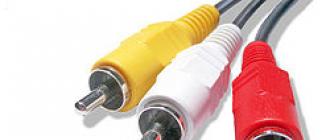
The manipulator was done under the left hand. Thumb - dots, index - dashes. As a cable, I used a piece of headphones for a smartphone with a 3.5 mm minijack. Screen - on the central clip, left, right channels - on the side ones.
Now it's up to the key. Industrial radios usually have a built-in key circuit, but I'm making a Morse code kit for training, so I started looking for a suitable prototype circuit. The first version was assembled according to this scheme: http://www.radionic.ru/node/1026
The scheme worked. But with some nuances. Sometimes lags are observed in the form of repetition of characters (instead of one dash - two, etc.). Apparently, due to the imperfection of the manipulator and, as a result, contact bounce.
It was decided to modify the circuit a little, in particular, in terms of noise immunity. For this, Schmitt triggers are installed at the input from the manipulator.
The final circuit, after debugging, looks like this:

On the DD1 microcircuit, a dot generator is assembled, which also works in the dash generation mode. Its frequency determines the transmission rate. It is started by applying a logical zero to input 6 DD1, formed by the closure of the manipulator, passed through two Schmitt triggers. Why two? There are already six inverters in the 4584 microcircuit, and I only need two, but a repeater. Including two inverters in series, we get the inversion of the inversion, i.e. repeater. In this case, the signal is already freed from the "bounce". On the left half of the DD2 flip-flop, the frequency divider is assembled by 2. Thus, we get a guaranteed "meander", even if the pulses of the master oscillator are not entirely symmetrical. The duration of the pause between points is equal to the duration of the point. This is the Morse code standard. On the second half of the DD2 trigger, a frequency divider by 2 is also assembled, but it works only when the manipulator is closed to the "dash" position, when a logical one is removed from its input "R" (reset). Thus, at the output, we get the pulse and pause duration at two points. The point generator also works in this case. The "double dot" is added to the "single dot" on the 2-AND-NOT element, thus we get the duration of a dash in three dots, the pause between dashes is one dot. This also applies to the Morse code standard. Changing the dot generator frequency changes the baud rate, but the standard ratios remain in effect. The circuit implements "self-grabbing", i.e. if, say, close the manipulator to the "dash" position for a time shorter than the duration of the dash, then the character will still be issued to the end, of the standard duration. The same applies to points. This is done using diodes. A sound generator is assembled on the DD3 microcircuit to control the operation, from its output the bass tone is fed through a transistor amplifier to the buzzer. The desired tone frequency is adjusted with R7. The output signal is also indicated by a light signaling on the HL1 LED. A relay can be used to switch a telegraph transmitter.
The assembly was carried out using SMD components. The board is laid out in the Sprint-Layout program, manufactured by the LUT method. After fixing all the identified errors:

Photo of the assembled device:

Lead-free, but an anti-slip mat from a car dealership won't hurt.
During the development process, several mistakes were made, it was necessary to promptly correct:

The key works without remarks, no lags are observed.
Well, I did not understand the first version of the key. So, it turned out I had two of them. It was decided to leave one for training the Morse code, and the second to "make friends" with the Chinese QRP micro-transceiver "Pixie", bought in the form of a constructor, for the sake of curiosity, for $ 5. And the tea box came in handy:

Video of the devices is attached.
List of radioelements
| Designation | Type of | Denomination | Quantity | Note | Shop | My notebook | |
|---|---|---|---|---|---|---|---|
| C1, C5 | Capacitor | 220 nF | 2 | SMD 1206 | Into notepad | ||
| C2, C3 | Capacitor | 2.2 nF | 2 | SMD 1206 | Into notepad | ||
| C4 | Capacitor | 15 nF | 1 | SMD 1206 | Into notepad | ||
| C6 | Capacitor | 47 nF | 1 | SMD 1206 | Into notepad | ||
| C7 | Electrolytic capacitor | 100 uF * 10V | 1 | Into notepad | |||
| DD1 | Chip | 4001 | 1 | SMD | Into notepad | ||
| DD2 | Chip | 4013 | 1 | SMD | Into notepad | ||
| DD3 | Chip | 4011 | 1 | SMD | Into notepad | ||
| DD4 | Chip | 4584 | 1 | SMD | Into notepad | ||
| EP1 | Sound emitter | LD-BZEN-1212 | 1 | Into notepad | |||
| HL1 | Light-emitting diode | diffuse | 1 | 3 mm | Into notepad | ||
| R1-3, R6, R10, R12-13 | Resistor | 100 kΩ | 7 | SMD 1206 | Into notepad | ||
| R4 | Variable resistor | 200 kΩ | 1 | Into notepad | |||
| R5, R8, R9 | Resistor | 20 kΩ | 3 | SMD 1206 | Into notepad | ||
| R7 | Trimmer resistor | 47 k Ohm | 1 | SMD | Into notepad | ||
| R11 | Resistor | 200 | 1 | 0.5W | Into notepad | ||
| VD1-7 | Rectifier diode | ||||||
SPORTS EQUIPMENT
Economical
Among radio amateurs, electronic telegraph keys on TTL microcircuits are widespread. They are characterized by a relatively high consumption of electricity and. as a rule, the need to stabilize the supply voltage All this makes it difficult to power them from batteries. This problem does not arise if the key is executed on economical CMOS microcircuits, for example, a series
resistance is less than indicated in the diagram. Element DD1.3 provides the discharge of the capacitor O through the resistors Rl. R2 to equalize the duration of the first pulse relative to subsequent
Trigger DD2.I forms "points". A “dash” is obtained by adding a “dot” and a “double dot” formed by the DD2.2 trigger in element DD3.I.
On the logic gates DD3.2 - DD3.4, a self-control generator is made. the signal of which can be listened to through the BFI headset or through the reuicTop R10 fed to the audio amplifier of the receiver. The frequency of the generator
SHI KP6LE5; Zh KP6TMG, Zh KL6LA7
him UK: ^ max. R9 Mountain Massacre
reduce to 1 kOhm to ensure the key mode of operation of the transistor VT2.
As DD2, you can use the K176TM2 microcircuit. while its outputs S (pins b and 8) must be connected to a common wire. VDI-VD5 diodes - any small-sized silicon, VTI-VT3 KT315 transistors with any letter index
The details of the telegraph key are placed on a printed circuit board (Fig. 2) made of one-sided foil material with dimensions of 65X35 mm
KI76. A schematic diagram of such a key is shown in Fig. 1.
The clock generator operating in standby mode is assembled on a DD1 microcircuit. Resistor R2 regulates the baud rate in the range from 60 to 200 characters per minute. If there is a need to work at lower speeds, then you need to take a resistor R2 with a higher rating. If it is required to raise the upper limit of the speed, then the resistor RI must have
the torus is installed with a resistor R5. It can be omitted, but the RC must be matched to the desired pitch.
The key is designed for contactless manipulation of the transmitter using a transistor VT2. In the collector stump VT2, you can turn on a manipulation relay, the winding of which is shunted by a diode. The relay can also be powered by a higher neck voltage by using a transistor with a higher voltage as VT2.
In rest mode, the key consumes almost no electricity, so the power switch may be missing.
The efficiency of the electronic telegraph key remains when the blinking voltage drops to 4 V. only the speed scale shifts slightly and the frequency of the tone generator decreases
pos. Vyhma X. RAUDSEPP
Estonian SSR
RADIO N9 4, 1986
Miniature electronic telegraph key MINI CW KEY on the ATtiny13 microcontroller
This simple electronic telegraph key was developed by Alexander Denisov (RA3RBE) from Tambov. A detailed description of this design is posted on the author's website. In addition, there you can familiarize yourself with other no less interesting designs, as well as ask questions.
When developing this telegraph key, the task was to make the device very simple, available for repetition by radio amateurs of any level of training, from beginners to pros.
In addition, the operation of this device should satisfy both an inexperienced telegraph operator and a radio amateur who has devoted many years to working on the key.

The circuit diagram of the key is very simple, the core of this circuit is the ATTiny13 microcontroller. It generates an output telegraph signal with a ratio of 1: 3, regulates the transmission rate in a wide range of speeds, and provides self-control through a connected miniature capsule. At the output of the key there is a MOSFET which can be controlled directly by the transmitter or you can include a relay in its drain for control through the relay contacts.

Dimensions of the key PCB: 47x39 mm. The variable resistor and the telegraph key socket are installed in such a way that the board can be fixed to the front panel of the device directly with the nuts of the socket and the variable resistor "Speed". There is a jumper on the printed circuit board to turn off the sound signaling device, if necessary. Self-assembly kits are completed with a pre-programmed microcontroller and a socket for its installation.
Brief assembly instructions and kit contents can be seen
The cost of a printed circuit board (board dimensions 47x39 mm): 50 UAH.
The cost of a set for assembly: 160 UAH.
The cost of the collected and verified board: 190 UAH.
A short video demonstrating how the key works:
To purchase sets, please contact (please note that in the "Security Code" box, you must enter the numerical result of the specified arithmetic operation) or
Good luck to everyone, peaceful sky, goodness, 73!
Automatic telegraph key
For many years now, radio amateurs-athletes and telegraph operators of communication centers have preferred to use an automatic telegraph key to transmit Morse code. This electronic device, controlled by a mechanical manipulator, provides a clearer transmission of Morse code characters with less stress on the operator's fingers. It also allows you to easily adjust the rate of transmission of the characters of the telegraph alphabet, without violating the accepted ratio of the duration of the sound of dots and dashes (1: 3).
We offer for practical use a simple automatic telegraph key on three microcircuits of the K155 series (Fig. 1).

Fig 1. Telegraph key
It contains a clock generator on elements DD1.1-DD1.3, a shaper of "dots" and "dashes" on D-flip-flops DD3.1, DD3.2, a pulse adder on an element DD2.4, a tone generator on elements DD2.1, DD2.2 and transistor VT1, which serves for auditory control of telegram transmission, a transmitter control unit for an amateur radio station (transistor VT2 and an electromagnetic relay K1) and a manipulator SA1 with an element DD2.3.
How does such a telegraph key work? In the neutral position of the manipulator SA1, when its armature does not touch the side contacts, the clock generator does not work, since it is blocked by a low-level voltage at the lower input of the element DD1.1, connected to a common wire through a resistor R3 of relatively low resistance. The control tone generator is also blocked by low-level voltage from the output of element DD2.4. This element is in the zero state because at this time a high level voltage acts on the direct output of the DD3.1 flip-flop and the inverse output of the DD3.2 flip-flop.
The operation of the telegraph key is illustrated by the timing diagrams shown in Fig. 2.

Rice. 2 Timing diagrams
To form a "dash", the armature of the SA1 manipulator touches the left (according to the diagram) contact. Element DD2.3 switches to a single state and starts the clock generator with a high-level output voltage. From this moment on, the output of the matching inverter DD1.4 appears the pulses of the clock generator (diagram a in Fig. 2), which are fed to the input C of the flip-flop DD3.1. The period of the pulse sequence of the clock generator, regulated by the variable resistor R1, is equal to the duration of the "point".
On the front of the first pulse, the DD3.1 flip-flop switches to the opposite state, as a result of which a low-level voltage appears at its direct output, which transfers the DD2.4 element to a single state. At the same time, the tone generator is turned on, since now a high level voltage has appeared at the upper input of the DD2.2 element. The audio pulses are amplified by the transistor VT1, which is connected by the emitter follower, and from the engine of the variable resistor R7, which is connected to the emitter circuit of the transistor, the pulses are sent to the BF1 headphones. At the same time, relay K1 will work, the contacts K1.1 of which are manipulated by the transmitter.
On the front of the second pulse of the clock generator, the flip-flop DD3.1 switches to the single state and by the voltage drop at the inverse output switches the flip-flop DD3.2 to the zero state (diagrams b and c in Fig. 2). Now, at the lower input of the element DD2.4, there will be a low-level voltage, but the single state of this element will remain for the duration of two "points" (diagram d in Fig. 2). Only on the front of the fourth pulse of the clock generator, when both flip-flops take their initial state, the DD2.4 element will go to zero and the low-level output voltage will block the tone generator. At the same moment, the relay K1 will release. There comes a pause, which is equal in duration to the "point", the next cycle of the formation of the sign begins. The duration of each "dash" is three times longer than the "dot" period, which corresponds to the rules for the transmission of the telegraph alphabet.
For the formation of "points" the anchor of the manipulator SA1 is set to the right position. In this case, the DD2.3 element is again in a single state and starts the clock generator through the VD1 diode. At the same time, a low level voltage appears at the input R of the DD3.2 flip-flop, as a result of which the flip-flop is blocked in the zero state. The high level voltage at the inverse output of this trigger will not prevent pulses coming from the direct output of the DD3.1 trigger from acting on the DD2.4 element. At the output of this element, "points" will be formed until the armature of the manipulator is set back to the neutral position.
What is the purpose of the diodes VD1-VD3? Diode VD1 - decoupling. When the element DD2.3 goes into a single state, a high voltage is supplied from its output through this diode to the lower input of the element DD1.1, which starts the clock generator. This diode, in addition, prevents the low-level voltage from the DD2.3 element from entering the lower input of the DD1.1 element during those periods of time when the DD2.4 element is in a single state and the high-level output voltage supports the clock generator in the generation mode. Therefore, both "points" and "dashes" will be formed completely, regardless of the moment the manipulator returns to the neutral position.
Diode VD2 also performs a decoupling function so that the low level voltage at the output of DD2.4 does not interfere with the operation of the clock generator.
Thanks to the VD3 diode, regardless of whether the armature of the manipulator is transferred to the right or left position, the DD2.4 element will switch to a single state.
Due to the inclusion of the transistor VT1 by the emitter follower, the resistance of the BF1 headphones does not really matter. Resistor R8 limits the collector current of the transistor in the event of an unintentional short circuit of the emitter of the transistor to the common wire.
A drawing of the circuit board of the electronic part of the automatic telegraph key is shown in Fig. 3.

Rice. 3 Wiring diagram
All fixed resistors are of MLT-0.25 type, oxide capacitor C1-K50-6. Electromagnetic relay K1-RES55 (passport RS4.569.724). Choke L1 is wound on a ring with a diameter of 8 and a height of 4 mm made of 600NN ferrite; it should contain 150-200 turns of PELSHO 0.25 wire.
If the telegraph key is not yet supposed to be used for joint operation with the radio station transmitter, then the entire transmitter control unit starting with the resistor R8 can be excluded. In this form, the device will help the successful mastering of high-speed reception by ear and transmission of the telegraph alphabet.
A possible design of an automatic telegraph key manipulator is shown in Fig. 4.


Rice. 4 Construction of the manipulator
The base 1 of the manipulator is two plates folded together made of durable insulating material (for example, textolite), fastened at the corners with screws 9, 10. Anchor 2 is a plate 115 ... 120 long and 15 ... 18 mm wide, cut from double-sided foil fiberglass. It is fastened with screws 4 between two metal corner posts 3 and is held in the neutral position by rectangular shock absorbers 6 made of foam rubber glued to the base.
On the corner posts 7 made of steel or brass, fixed on the base with screws with countersunk heads, there are adjusting screws 8, which form fixed contacts of the manipulator. Against them, on both sides of the armature, contacts are soldered from the contact plates of an unusable electromagnetic relay, for example, MKU-48 or the like. After installing the necessary gaps between the armature and the side contacts, the adjusting screws are fixed with nuts 11.
The conductors connecting the circuit board with the manipulator are soldered to the petals 5 located under the corner posts.
Read and write usefulThis electronic telegraph key is made using only two simple microcircuits K155LA3 and K155TM2. The circuit diagram is very simple.
A clock generator is assembled on elements DD1.4 and DD1.1, the frequency of which can be adjusted with a variable resistor R1. On element DD1.3, a generator start unit is made. Trigger DD2.1 forms "points", DD2.2 - "double points".
When the manipulator is moved from the middle position to the "Points" position, a logical "0" is sent to pin 9 of the DD1.3 element. In this case, a logical "1" comes to the inputs of the DD1.4 element, and the clock generator begins to form a rectangular pulse.

At the inverse output of the DD2.1 trigger, a low logic level immediately appears, which is fed through the VD1 diode to the generator start unit. This allows the formation of "points" of the same duration, regardless of when the manipulator was returned to its original state. Pulses from the direct output of the trigger DD2.1 through the VD5 diode are fed to the transistor VT1 operating in the key mode. Relay K1 is included in its collector circuit, which switches the corresponding transmitter circuits.
When the manipulator is moved to the "Dash" position, a low logic level is applied to pin 9 of DD1.3 and pin 5 of DD1 2. At the same time, the clock generator starts to work. From the inverse trigger output DD2.1. as well as from DD2.2 through the diodes VD1, VD3, VU4 to the elements DD1.3 and DD1.2, a logical "0" arrives, which ensures the operation of the clock generator during the formation of a "dash" of normal duration. "Dash" is obtained by summing the "points" and "double points" on the resistor R3, coming from the direct outputs of the flip-flops DD2.1 and DD2.2 through the diodes VD5 and VD6.
The electronic key parts are placed on a 65x45 mm printed circuit board.


In the key, you can use microcircuits of the K133, K158, K130 series. Diodes VD1-VD6 - any pulse, transistor VT1 - any low-power structure n-p-n. Relay K1 - RES-15 (passport RS4.591.002). Instead, you can use RES-43 (passport RS4.569.201) or others whose operating voltage does not exceed 5 V.
You can download other schemes and solutions of telegraph keys