Amplifiers for guitars are always of great interest to radio amateurs and musicians. A variety of timbres, gain, overload characteristics are always individual, and each guitarist has his own “ideal” requirements for each guitar. There is no amplifier that satisfies universal requirements and this design is no exception.
The only difference is that you build it yourself. The design is designed so that you can experiment with each node and during the modification process achieve the result you need. The design is based on standard, well-known schemes of nodes and blocks. The design is easy to repeat, has increased reliability and relative cheapness.
The amplifier has an output power of 100 W at a load of 4 ohms, which is typical of a conventional “combo” in which two speakers of 8 ohms are installed in parallel. You can also run the amplifier in a block with four speakers, connecting them in series and parallel, while the output power will be about 60 watts (8 Ohm load). You can also use two speakers with four speakers in each. In this case, you can achieve much better sound while maintaining the output power at 100 watts. This is a typical combination for guitar complexes, allowing you to more fully use the capabilities of the main amplifier.
Preamplifier
The preamplifier circuit is shown in Fig. 1. The circuit has several features that distinguish it from a conventional pre-amplifier typical ULF.
The preamplifier is designed in such a way that allows you to get the maximum gain and form a “juicy”, strong sound for fans of forced sound. However, through the settings, the preamp can be used for any style of play.
Similarly, changing the tone settings, the amplifier can be used with any instrument: from an electrified violin to a bass guitar. Moreover, it should be noted that all these tools have different values \u200b\u200bof the amplitude of the output signal, therefore, in the manufacturing process, you should configure the pre-amplifier in accordance with the intended application. Using all the features of the preamplifier with careful tuning, you can get high-quality sound without specific low-frequency distortions that bass players don't like.
It can be seen from the circuit (Fig. 1) that the preamplifier uses an imported low-noise operational amplifier. type TL072 specially designed for use in the input stages of the ULF. This chip is easy to purchase on the market today. You can additionally reduce the noise level in pauses by using the dual mapo-noise op-amp OU 5532. It is more expensive than TL072 and less accessible, but its use will provide a low noise level at rest. You can apply domestic K544UD1 or K1407UDZ.
The signal from the output of the electric guitar is fed to the input of the OA DA1.1, at the output of which a signal is formed with a quick “attack”. The frequency response of an amplifier on DA1 is deliberately limited to eliminate distortion at low frequencies and “cut off” high-frequency bursts, as well as improve the signal-to-noise ratio, which is not an easy task when creating guitar amplifiers.
Fig. 1. Preamplifier circuit
If there is no need to obtain the maximum amplification of the cascades, it is necessary to increase the value of the resistors R7 and R14, which will lead to a decrease in the gain and intrinsic noise. The switch SA1 connects, in addition to the correction circuit, a chain R3, C2, which shifts the frequency response of the amplifier towards higher frequencies, increasing the brightness of the sound of an electric guitar. By changing the position of the slide potentiometers R9 ... R11 change the overall frequency response of the amplifier path. The narrowest band is obtained when the engines of all potentiometers are set to the lower position.
At the output of the preamplifier, a limiter is assembled, assembled on diodes VD1 ... VD4. It allows you to make a soft “trim” of the amplitude of the output signal. For normal operation of the limiter, the output signal level must be at least 750 mV, so the total gain of the preamplifier must be selected so that the output signal reaches the specified level in the middle position of the level controller R12.
During installation, the input connectors must be properly shielded. Proper grounding of the components of the power supply also reduces the background of the alternating current. The preamp power from a separate power source also helps in this. Proprietary guitar amplifiers often use just such a circuit design.
“Hi” input is used to connect guitars with a low output level.
The “Lo” input reduces the sensitivity of the preamplifier by b dB by connecting the resistor R1 to the housing through an additional contact of the XS1 connector, which closes if the electric guitar plug is not inserted into the “Hi” input.
Amplifier
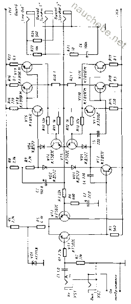
The basis is a diagram of a typical low-frequency amplifier with a differential cascade. The circuit (Fig. 2) was developed to obtain an output power of 100 W and showed good test results. Of course, in terms of sound quality, it is inferior to a tube amplifier, but somewhat better than a conventional transistor. An output short circuit protection implemented on transistors VT4 and VT5 is introduced into the amplifier. When the amplifier output is shorted, the voltage drop across the resistors R20 and R21 exceeds 7 V (normal value at the peaks of the maximum output power). This voltage opens transistors VT4 and VT5 and they respectively close the transistors of the output stage. Maybe this is not the best construction of a protection circuit, but it allows you to protect expensive output transistors from instant breakdown in case of short circuit. The amplifier was not designed to operate in overload mode, so the output current is limited to about 8.5 A.
There are additional “Output” and “Input” jacks at the input of the amplifier. The latter is switched by the contacts of the XS3 jack, so it is possible to connect an external effects unit. Also, the input jacks can be used to connect an external preamplifier by disconnecting the internal one, and use only the PA.
In the output stage, various powerful transistors can be used. The use of transistors of the type KT818GM and KT819GM \u200b\u200bmade it possible to obtain high reliability of the output stage with a rather light mode of operation of the output transistors. In addition, there was no need for temperature protection of the output transistors, since when using two transistors connected in parallel in each arm, the thermal regime does not exceed the maximum permissible.

Fig. 2. Scheme of a typical bass amplifier
A good result is obtained when using any powerful transistors made in the TO-3 package (this package has lower thermal resistance). There is a fairly wide selection of imported and domestic powerful transistors on the market that can be used in this circuit. The amplifier works well with anyone, if their characteristics are not lower than those shown in the diagram. To exclude the failure of the output stage, the operation mode of the transistors is chosen in the field of their safe operation. Diodes VD2 ... VD3 must be silicon type D223, KD503, KD509 or others, like them. Transistors VT6 ... VT11 must be installed on radiators. The signal from the “Line out” line output has a level of about 1.3 V, and therefore it can be fed directly to a sound recorder or other device. The level of the output signal from the linear output can be changed by selecting the value of the resistor R22. Resistors R20 ... R21 with a resistance of 1 ohm are designed for power dissipation of at least 10 watts. Even with such power, they heat up very much, so during installation they must be installed away from other parts of the circuit. They can be installed on small radiators or on the radiators of output transistors, if the latter provide additional heat dissipation (each resistor adds about 10 watts of thermal power). Resistors R16 ... R19 with a nominal value of 0.1 ohm-power of 5 watts each.
The operating mode of the guitar amplifier is very tough, so you should not save on the size of the used radiators. Use the radiators that are most affordable for you for this purpose and, thus, you will increase the reliability of your design.
Two columns of 75 ... 100 W, 8 Ohms in parallel (RH \u003d 4 Ohms) or 1 column 150 ... 200 W, Rh \u003d 4 Ohms can be connected to the amplifier output. When the load resistance Rh \u003d 8 Ohms, the output power of the amplifier decreases to 60 ... 65 watts.
Power Supply
When designing the mains power supply, be careful, as breach of safety precautions may result in electric shock.
The power of the power transformer T1 of the power supply (Fig. 3) must be at least 150 watts. If possible, it is better to use a toroidal one - it has a smaller scattering field and smaller dimensions at the same power. The primary winding is protected by a fuse FU1, rated for a current of 5 A. A bridge rectifier for a current of at least 5 A is installed on the radiator. Powerful Zener diodes VD9..VD10 for stabilization voltage ist \u003d 15 V are also installed on small heat sinks together with current-setting resistors R2 and R3, away from the rest of the circuit elements, because during operation, they become very hot.
The node on the elements VD5 ... VD8, R1, C1 is designed to separate the “electric” ground of the circuit and the grounding circuit of the network in order to prevent the AC background from “creeping” from electrical equipment and to protect the guitarist from electric shock in the event of a malfunction of the power transformer of the power supply unit. A 10 ohm resistor R1 prevents the background of the alternating current, and a capacitor C1 with a capacity of 0.1 μF serves to eliminate RF interference. In case of damage to the power transformer (breakdown of the network winding to the secondary or to the housing), the diode rectifier shorts the current to the ground that occurs when it is damaged and, thus, protects the guitarist from damage. Despite the fact that this malfunction is extremely rare, it is better to protect yourself initially when designing an amplifier. In general, when creating structures that are supposed to be operated in “harsh” conditions (namely, guitar “combos” belong to these), we should pay special attention to electrical safety issues.
After the installation is completed, make sure that all current-carrying wires connected to the electric network are carefully insulated and firmly fixed. The wire connected to the contour ground must be connected to the chassis of the structure through a separate bolt (can not be used to connect the bolts of the circuit elements).

Fig. 3. Power supply circuit
The wire is connected to a separate grounding bolt between the two washers and tightened with two nuts (the second is a locknut) to prevent the fasteners from weakening from vibration during operation. The amplifier can be placed in the housing of one of the speakers or assembled as a separate structure. In any case, installation and construction must be performed very carefully.
The design of speakers can be very diverse and depends on the applied dynamic heads.
The proposed design options for speakers have been repeatedly repeated and have shown high operational characteristics. Both options are made on the principle of open speakers. This eliminates the natural resonant frequencies of the case and when using modern mid-frequency dynamic heads allows you to get high quality sound.
The first option (Fig. 4) is one column in which two dynamic heads of 75 ... 100 W (RH \u003d 8 Ohms) each are installed. The use of such powerful emitters is, again, associated with an increase in the reliability coefficient and the desire to have some margin in power. When using 50 W emitters, 8 Ohm speakers will operate in extreme mode, and reliability will decrease dramatically.
The second option (Fig. 5) is the use of two columns with 4 speakers of 35 ... .50 W (Rh »8 Ohms) in each. When connected in parallel, the total load resistance is Rh \u003d 4 Ohms, the electrical power is kept at 100 W, but the sound quality is much better.
AC enclosures are assembled from MDF panels 22 ... 25 mm thick. Using MDF allows you to get a mechanically strong, durable design, little susceptible to strong vibrations.

Fig. 4. Speaker design options (single column)

Fig. 5. Speaker design options (two columns)
If you use conventional chipboard (which is somewhat cheaper), the service life of such a case is significantly reduced, especially if the amplifier is designed to work with moving to different stages and platforms.
All elements of the body are glued and fastened with special furniture bolts with a T-nut. This increases the mechanical strength and durability of the housing. In addition, wooden bars with a cross section of 25 × 25 mm are glued and screwed on the inside of the ends. Particular attention should be paid to the fastening of the dynamic heads to the front panel. The heads should be bolted with nuts, not screws. Between the speaker and the head, it is necessary to lay a gasket of soft material (for example, rubber or plastic) to ensure a tight connection. When working with MDF, it is necessary to carefully mark out and prepare holes for fastenings with a drill. This will prevent damage to the sectional plane of the slab. The quality of MDF panels allows you to do without external decoration, only the end planes need to be repaired with a special tape, which is sold together with the panels.
For some time, having given way to transistors, and then to microcircuits, the radio tubes returned to the hams of the radio amateurs again. Currently, these electrovacuum devices have gained great popularity among fans of good sound. This applies to both musicians and those who listen to their recordings. Numerous companies have responded to demand, and now it’s possible to buy a decent amplifier in stores without much hassle, but their cost in some cases is simply astronomical. As a result, many hams learn the basics of building equipment on radio tubes, constructing various amplifiers for their headphones, powerful audio systems and musical instruments. And I did not "pass" by, deciding to take up the amplifier for my guitar.
For the basis of the future design, I took the well-proven pre-amplifier circuit Slo Recto Twin Designs of well-known among enthusiasts of tube musical equipment Gishyan * AZG * Aznaura. To the “pre” I added a 6P3S push-pull power amplifier for beam tetrodes, anode voltage feed delay circuit and footswitch switching.
Circuit diagram
Structurally, the amplifier consists of a pre-amplifier for lamps VL1-VL3, a push-pull power amplifier (lamps VL4-VL6) and a common power supply.
The preamplifier, in turn, consists of two channels - pure (clean) and overload ( distortion) with separate tone and volume controls.
The signal from the guitar pickups is fed to the grid of one of the two triodes of the VL1.1 lamp, which is a common amplifier for both channels. In the cathode bias circuit of the triode, using one of the relay contact groups, the non-polar capacitor C1 is switched, which is included in the circuit in pure sound mode and extends the amplified frequency band in the low-frequency region. In the overload mode (the relay is triggered), it is isolated by the large resistance of the resistor R3, so only the capacitor C2 remains, which has a relatively small capacity. In this case, the amplification of the cascade is noticeably reduced at low frequencies, which prevents the "muttering" of sound.From the anode of the triode, the signal is divided into two channels. The upper one works in the mode of amplification of pure sound, the lower one in overload. Channelclean represented by three-way (treble - high bass - low middle - average frequency) by the tone control, assembled according to the fender circuit, and the amplification cascade on the VL1.2 triode.
Overload ( distortion) is already implemented by a much larger number of lamps and passive elements. Three stages on VL2.1 triodes,VL2.2 and VL3.1 have a large common gain, due to which the sound greatly distorted. This creates an effect with a characteristic heavy and powerful sound.To coordinate these cascades with the tone control, as well as to prevent mutual influence, a cathode repeater on the VL3.2 triode is included in the circuit. In pure sound mode, the overload channel is locked by locking the grid of the VL2.2 triode.
To separately control the level of cascade signals, each of them is equipped with variable volume resistors R11 and R38. In addition, there is a general volume control R40 master volume.The motors of all volume controls are shunted by constant resistors, with a resistance of 2.2 megaohms. They are necessary to eliminate possible rustling caused by wear of the conductive layer. By themselves, they are not scary, but at the same time the mesh is torn off from the common wire, as a result of which the volume of the rustle becomes very high.
The amplified and processed signal from one of the channels is fed to the input of a differential phase inverter assembled on a VL4 lamp. Its task is to additionally amplify and create at the output two identical signals with a phase shift of 180 ° relative to each other for the operation of a push-pull power amplifier on 6P3S lamps.
Switching the channels of the pre-amplifier is carried out using two relays, which, in turn, are switched using a footswitch (you can select the desired channel by pressing the foot of a button, as in a lotion) or a switch on the front panel. There are also mode switches bright(S1) and treble shift (S2) to change the color of the sound of each channel. The VD13 indicator LED in the foot switch is connected to the switching relay circuit and lights up when the S6 button is pressed to turn on the channeldistortion. Capacitor C57 with a relatively large charging current at the moment of pressing the button ensures reliable operation of the relay, since the current flowing through the LED may not be enough for this.
The amplifier is powered by a transformer power supply with passive filtering of the anode voltage with a delay circuit, and with a voltage stabilizer for the filament voltage of 12AX7 lamps. Ultrafast UF4007 diodes are used in the anode voltage rectifier, due to which it is possible to almost completely get rid of switching noise of switching diodes. In order to supply power to the lamps only after heating their cathodes, the amplifier uses a delay circuit assembled on transistors VT3 and VT4. The K3 relay trips approximately 10-15 seconds after the amplifier is turned on (selected by C55 capacity) and closes the K3.1 contacts. The filament of the preamplifier lamps is powered by a stabilized voltage of 12.6 volts to reduce background and noise, as well as to increase the life of these electric vacuum devices. The voltage at the cathode of the repeater VL3.2 is quite large due to the high resistance of the resistor R33, which creates a significant potential difference between the cathode and its incandescence, which greatly reduces the lamp operating time. To neutralize this effect, the glow potential "rises" relative to the common wire by about 75 volts. The corresponding voltage is supplied from the divider R67 and R68 to the symmetrical glow divider R65 and R66. The same divider is installed in the glow circuit of the output lamps (6.3 volts), but its midpoint is connected to a common wire.
The isolation of the earth is made according to the "star" scheme, when the wires from the circuits of the common wires of different cascades are connected at one point and have reliable contact with the amplifier housing.
Details
All fixed amplifier resistors must be metal film (MF) or metal oxide (MO). They have less noise, unlike CF carbon resistors. Domestic MLT resistors are also suitable.
Film capacitors must be of the Wima or Epcos MKP series for a voltage of at least 400 volts. These "musical" capacitors are quite common. You can also use the good domestic K71 series. Somewhat worse results are given by consumer goods K73. Old metal paper capacitors such as MB or MBM should beware. As a rule, even the most "new" instances are more than 30 years old and almost all of them have significant leakage currents. Electrolytic capacitors are best used with a maximum operating temperature of 105 degrees due to their proximity to hot lamps. For capacitors in the anode circuits, the voltage should be at least 400 volts.The capacitors shunting them 0.022 microfarads must be of type X2, designed to operate in an alternating voltage circuit of at least 275 volts. They have a working DC voltage of 600-1000 volts, and low internal impulse current resistance contributes to good filtering of noise and ripple. Instead of non-polar electrolytes C1 and C10, ordinary polar electrolytes can be used. Small capacitors in the timbral units and in the bass reflex are better to take film, mica from the KSO and SGB series or imported high-voltage ceramic blue capacitors.
The preamplifier uses 12AX7 lamps from Tung Sol produced in Russia. Instead, you can useECC83 or domestic 6N2P-EV. In this case, the glow voltage should be reduced to 6.3 volts. To do this, it is necessary to replace the Zener diode VD9 with another one with an operating voltage of 3.3 volts. With some deterioration in sound quality, you can use 6N2P, 6N23P and even 6N9S, as well as other double triodes. Common output tetrodes 6P3S were used as output lamps.
The transistors in the delay circuit, as well as VT2 in the filament stabilizer of the preliminary lamps, can be any silicon low-power n-p-n structures with a minimum emitter current transfer coefficient of 100. For example, KT315, KT3102, SS9014, and so on. Power transistor VT1 must have a maximum collector current of at least 4 amperes and a maximum voltage of at least 100 volts. If its case is not insulated (TO-220FP), then it should be attached to the radiator through the insulating heat-conducting gasket "nomacon", and the tightening screw should be equipped with a plastic washer.
It is advisable to use diodes in the anode rectifier VD1-VD4 ultrafast, such as UF4007, but you can also put ordinary rectifier with a maximum reverse voltage of at least 600 volts and a direct current of 1 ampere. In this case, each of them is shunted by a film or ceramic capacitor with a capacity of 0.01 μF to a voltage of at least 630 volts. VD5-VD8 diodes with a Schottky barrier, they can be replaced with any c with a maximum direct current of at least 3 amperes.
I used specialized relaysfor switching audio signals - 46ND012-P by FUJITSU . But you can apply any with an operating voltage of 12 volts, withtwo switching groups and minimum tripping current.
Transformers and chokes homemade. The first are wound on frames and cores from the Russian computer "Corvette" produced in the mid-90s. Their tape U-shaped magnetic cores have a small scattering field and can be installed without magnetic screens. Any transformer iron with a cross section of 6 cm 2 is also suitable. Data on windings and voltages are given in the table in the diagram. Between layers, lay one layer of varnish or thin capacitor paper, and between the windings the number of layers should be at least three. Between the halves of the magnetic cores are placed insulating linings of varnish, 0.3 mm thick. Inductors are wound with 0.25mm wire to fill the frames. Their cores must be a cross-section of at least 2 cm 2 with a dielectric insulator between their halves.
Design
Attention! In this amplifier, as in most other lamp devices, there is a high voltage, dangerous to life and health, therefore, all installation work and adjustment should be carried out in compliance with safety precautions!
Structurally, the amplifier is made on an open duralumin chassis, repeating the design approach to the design of tube audio amplifiers. Variable resistors, almost all connectors and switches are mounted on the front panel, which has an easy-to-use bend at an angle of 45 degrees. The fuse sockets FA1 and the output of the sound transformer, as well as the power connector are located on the rear wall.
The footswitch is assembled in a separate rugged case, connected to the amplifier with a long cable.
The printed circuit board is quite long, so the thickness of the foil fiberglass should be at least 3 mm to avoid unnecessary deformation. if such material cannot be found, then it is possible to use a common one with a thickness of 1.5 mm, but it is necessary to provide holes for attaching the racks in the middle of the board.
Adjustment
Despite the rather large complexity of the circuit, the amplifier starts working immediately after switching on, unless, of course, all the details used in it are operational. However, the operation of the device should be checked step by step. At the beginning, the amplifier turns on without lamps and the operation of the delay circuit is checked. Further, by adjusting the tuning resistor R63, the incandescent lamp voltage of the pre-amplifier is set to 12.6 volts. Further, already with the lamps, it is necessary to again adjust this voltage, which will "fall" under the load. After that, the voltage across the capacitors of the anode supply is measured. It should be 330-360 volts. It should be noted that for a working amplifier these indicators will be lower.
Next, insert into the corresponding socket of the lamp of the power amplifier VL4-VL6. A shielded wire is temporarily soldered to the top output of the variable resistor R40, the second end of which can be connected to any audio source - a player or a mobile phone. At the same time, clean, not distorted music should be heard in the speakers. Next, insert the VL1 lamp into the sockets and connect the guitar to the input of the amplifier, which switch to the "clean" channel. Make sure his good work. Then they insert the remaining lamps and check the channel already distortion.
The lamp modes were chosen optimal, and they remain so when using resistors with a standard tolerance of ± 5%, so no selection of elements is necessary.


Together with this amplifier I use a cabinet (“column” for guitar amplifiers) with the Celestion Vintage 30 dynamic head installed in it. It is not recommended to set the usual speakers used in automobile and domestic acoustic systems, since it is the guitar speaker with its special shape of the frequency response (blockage at medium frequencies) that forms the special sound of an electric guitar.
List of Radio Elements
| Designation | Type of | Face value | amount | Note | Score | My notebook |
|---|---|---|---|---|---|---|
| VL1-VL4 | Lamp | 12AX7 | 4 | ЕСС83, 6Н2П-ЕВ | To notebook | |
| VL5, VL6 | Lamp | 6P3S | 2 | To notebook | ||
| DA1 | Linear regulator | LM7812 | 1 | To notebook | ||
| VT1 | Compound transistor | 2SB1340 | 1 | To notebook | ||
| VT2-VT4 | Bipolar transistor | 2SC945 | 3 | KT315, KT3102, SS9014 | To notebook | |
| VD1-VD4 | Rectifier diode | UF4007 | 4 | To notebook | ||
| VD5-VD8 | Schottky diode | SR306 | 4 | To notebook | ||
| Vd9 | Zener diode | BZX55C6V8 | 1 | To notebook | ||
| VD11, VD12 | Rectifier diode | 1N4148 | 2 | To notebook | ||
| Vd13 | Light-emitting diode | L-132XHD | 1 | To notebook | ||
| C1, C10, C11 | 22 uF | 3 | To notebook | |||
| C2, C47C50 | Capacitor | 0.47 uF | 5 | To notebook | ||
| C3, C9, C12, C16, C18, C20, C24, C25, C27, C29, C38, C39, C41, C44 | Capacitor | 0.022 uF | 14 | To notebook | ||
| C4, C7, C22 | Capacitor | 220 pF | 3 | To notebook | ||
| C5, C8, C31-C34, C52 | Capacitor | 0.1 uF | 7 | To notebook | ||
| C6 | Capacitor | 0.047 uF | 1 | To notebook | ||
| C13 | Capacitor | 2200 pF | 1 | To notebook | ||
| C14, C17 | Capacitor | 1000 pF | 2 | To notebook | ||
| C15, C21 | Capacitor | 1 uF | 2 | To notebook | ||
| C19, C26, C38, C57 | Electrolytic capacitor | 10 uF | 4 | To notebook | ||
| C23 | Capacitor | 470 pF | 1 | To notebook | ||
| C28, C40, C43 | Capacitor | 3300 pF | 3 | To notebook | ||
| C30, C30 | Capacitor | 100 pF | 2 | To notebook | ||
| C35, C51 | Electrolytic capacitor | 470 uF | 2 | To notebook | ||
| C37, C39, C42, C54 | Electrolytic capacitor | 220 uF | 4 | To notebook | ||
| C46 | Electrolytic capacitor | 10,000 uF | 1 | To notebook | ||
| C53, C56 | Electrolytic capacitor | 47 uF | 2 | To notebook | ||
| C55 | Capacitor | 0.33 uF | 1 | To notebook | ||
| R1, R12, R16, R20, R41 | Resistor | 2.2 megohms | 5 | 0.5 watts | To notebook | |
| R2 | Resistor | 68 kOhm | 1 | 0.5 watts | To notebook | |
| R3, R60 | Resistor | 100 kOhm | 2 | To notebook | ||
| R4, R24, R32 | Resistor | 1.8 kOhm | 3 | 0.5 watts | To notebook | |
| R5, R31 | Resistor | 220 kOhm | 1 | 0.5 watts | To notebook | |
| R6, R7, R13, R22, R26, R33, R45 | Resistor | 100 kOhm | 7 | 0.5 watts | To notebook | |
| R8, R9, R35 | Variable resistor | 250 kOhm | 3 | B | To notebook | |
| R10 | Variable resistor | 25 kOhm | 1 | B | To notebook | |
| R11, R19, R36, R40 | Variable resistor | 1 megohm | 4 | A | To notebook | |
| R14 | Resistor | 820 ohm | 1 | 0.5 watts | To notebook | |
| R15, R21, R23< R30, R50, R51 | Resistor | 470 kΩ | 6 | 0.5 watts | To notebook | |
| R17, R42, R43 | Resistor | 10 kOhm | 3 | 1 watt | To notebook | |
| R18 | Resistor | 680 kΩ | 1 | 0.5 watts | To notebook | |
| R25, R47, R49 | Resistor | 1 megohm | 3 | 0.5 watts | To notebook | |
| R27 | Resistor | 39 kΩ | 1 | To notebook | ||
| R28 | Resistor | 330 kOhm | 1 | To notebook | ||
| R34 | Resistor | 47 kOhm | 1 | 0.5 watts | To notebook | |
| R37 | Variable resistor | 50 kOhm | 1 | A | To notebook | |
| R38 | Variable resistor | 50 kOhm | 1 | B | To notebook | |
| R39, R48 | Resistor | 22 kOhm | 2 | 0.5 watts | To notebook | |
| R44 | Resistor | 82 kOhm | 1 | 0.5 watts | To notebook | |
| R46 | Resistor | 470 ohm | 1 | 0.5 watts | To notebook | |
| R52, R53 | Resistor | 4.7 kOhm | 2 | 0.5 watts | To notebook | |
| R54 | Resistor |
It can be made if you have the necessary knowledge and experience for this. This publication discusses a device that is not very complex in design, but has great sound. The power amplifier circuit for the bass guitar presented here, in particular, the output stage is made with powerful bipolar transistors, and the preliminary amplification stage is implemented with electric vacuum tubes.
DIY Bass Amplifier and its design includes three modules: a triode preamplifier, a terminal amplifier, and a power supply. Of course, if necessary, any of these modules can be separately used in other devices. In the presented version, the amplifier is combined with a combined audio speaker, which allowed us to create a compact and convenient model, therefore, the power amplifier itself does not have a separate case, but is built into an additional box of the acoustic cabinet, located slightly above the speaker. The block of preliminary amplification of sound differs in its characteristic originality, and the end stage and the power source are made according to the standard scheme. p\u003e
Preamp module
DIY Power Amplifier It has excellent sound, mainly due to the pre-amplification cascade, which is made on electrovacuum triodes, providing a clean, transparent sound, in addition to this, the lamps have significantly lower noise than transistors. The elementary design of the device creates conditions for ease of assembly and reduces the cost of all components. Also, one of the important factors is that in the circuits made on lamps, there is no negative feedback, and this significantly increases the sound quality. Another indisputable advantage of the tube path is the ability to smoothly go into overload, this is especially important for sound amplification devices working with bass guitars.
In fact, the preamplifier is made on one twin lamp (VL1). Its first part is a standard circuit with a common cathode, which does not have any features. Without additional load and with a 12AX7 lamp installed, for example, the gain of this stage will be within 68. Therefore, the input signal does not limit, even if the supply voltage is about 200v and a powerful guitar signal is supplied. When the first stage is loaded with a timbre block, the amplified signal passing through it is somewhat reduced, this happens, due to the large resistance at the output.
DIY Bass Amplifier In the original version, a 6N2P-EV lamp was used. It was also tested with excellent performance, especially with a reduced supply voltage of up to 140v, a double triode 6N23P, in case there is a need to install other lamps, then you do not need to change the circuit. To find a specific sound, you can use 12AX7 lamps of various versions. By the way, 12AX7, just like the ECC83 dual triode, for which the voltage is directed to the glow channel 6.3v to the 9th output of the lamp panel, and the other wire is fed to 4-5 outputs connected to each other. In the original circuit, the lamp path received power from 150v, and later it was improved and the supply voltage became 250v. However, even at 150v the sound was of high quality.
Sound power amplifier
DIY Assembled Bass Amplifier It has a standard topology, there is nothing special in it. There are several built-in protections, in particular, the amplifier protection circuit against input voltage excess. The original design of the device was assembled without the use of a printed circuit board, all powerful output transistors are installed on a cooling radiator, except for transistors of a differential stage. VT4 performs the function of a temperature controller, therefore it is installed in close proximity to the output keys, which by the way are attached to the heat sink through insulating gaskets using KPT-8 heat-conducting paste.
The remaining electronic elements of the input stage are arranged on a solderless breadboard and are interconnected using a wall mounting method. DIY Bass Amplifier has in its scheme a small number of components involved, then their installation is quite easy. The circuit board itself is mounted on racks to the radiator in the area of \u200b\u200bthe output keys. The principle of establishing an amplifier occurs in the following order: - apply a supply voltage to the circuit, but without connecting output transistors. If everything is assembled correctly, the device without load will raise an audio signal without any distortion. Then you need to set the minimum bias voltage in the emitter circuit of the VT5 and VT6 pre-output transistors (within 1v) using the tuning resistor R14, all this must be done without load.
After that, it is necessary to connect the output stage and, again, with the R14 trimmer, set the quiescent current to 28-30mA, there is no need to give a high current value for the bass guitar to work. With the acoustical equivalent connected, at a small signal gain, we look at what the oscilloscope shows - there should be no “step” distortions on the sine, if nevertheless such distortion is present, then you need to add a bit of the quiescent current until the “step” disappears. The amplifier presented here can be freely replaced with another one, possibly available from you or want to buy in a store.
Non-polar capacitance installed in the circuit - film, designed for a voltage of 100v, and C8 and C12 at 250v are made of ceramic. If you intend to use the device at a power of less than 100 W, then you can reduce the supply voltage to ± 35v, and leave only two powerful complementary transistors in the output path.
It must be borne in mind that this design is made according to the version of the built-in amplifier in the audio column, and therefore there are no external switching elements for acoustics, therefore there is no short-circuit protection device in the load. When using an additional column, you will need to take care of installing a protection module in the amplifier. The principle of supplying the supply voltage is the same as for tube amplifiers, that is, the “Power” key is pressed, and when the lamps are fully warmed up, the “Standby” key connects the load and all the power to the power source.
Transformer power supply
The power transformer is involved in the TS-180, naturally, its secondary winding has been slightly changed. In the original circuit, to provide voltage for the filament of the lamp, there is a tap on the secondary winding. Of course, it would be more efficient to wind a special winding for such purposes, but in order for everything to be at a professional level, then you still need to integrate a rectifier that provides a direct current glow circuit. The value of the alternating voltage in the secondary winding without load should be 34v, and after the rectifier ± 50v. If you need to get an output power within 200 W, then you will need to pick up a transformer more powerful, for example: TC-250 or toroidal with the same power.
A dynamic radiator for the cabinet was used a low-frequency speaker with a size of 380 mm from the company CELESTION. In the original version, printed circuit boards were not created for one simple reason - the device should be assembled in a short time, and even then for personal needs, and it would have taken more time and money to develop the boards. Although this design may seem quite primitive, but the sound made a good impression. By the way, the famous bands “Araks” and “Ex-Smokie”, who were on tour, played the guitarist Allan Silson.
Here you can see the case with the speaker on the photo - this is the amplifier for the bass guitar made by yourself, and with the guitar in your hands - the bassist from the Ex-Smokie band.
Any music lover would like to hear a warm tube sound from his guitar, but not everyone can afford a good amplifier. This article will help you make a tube guitar amp with your own hands.
Some time ago, a friend of mine asked me to make an amplifier for him. I had a few lamps and a CD-ROM drive, and I decided that I could help him. In the video, my friend plays the guitar with the assembled amplifier. Let's start assembling a simple tube amplifier!
Step 1: Tools


To build you will need:
- soldering iron
- drill
- glue gun
- drills for metal and wood of different sizes
- large drill 1.3 cm
Step 2: Materials


Materials for assembly you need a little:
- power transformer that can supply 277-300 V
- 6V filament transformer
- switch
- powerful beam tetrode 6P6S
- 12A lamp - 7 pcs.
- cD-ROM drive
- 100K potentiometer - 2 pcs.
- 6.4 mm audio jack
- 0.02 uF capacitor - 3 pcs.
- 0.002 uF capacitor
- 120 uF electrolytic capacitor
- 10 uF electrolytic capacitor
- resistors: 10k, 32k, 100k, 1M
- bridge rectifier
- inductive choke
- output transformer 900: 4
Step 3: Preparing the CD-ROM Drive


When I started assembling the amplifier, I was looking for what to make a metal case for it, and decided to use the old CD-ROM drive. First remove the bottom cover and remove all plastic parts and electronics. Now push the hole in the top cover to remove the piece of metal that the sticker holds.
You should get a round hole, perfect for a tetrode. Now with a drill of 1.3 cm we drill holes for the preamplifier lamps. Then we drill holes in the front wall for the switch, potentiometers and an audio jack. They can be inserted into the holes provided for them.
Step 4: Mount the lamp holder


The lamp holder connects the lamps to the amplifier. I decided to make a lamp holder of wood, although you can just buy it. I painted the lamp contacts with a simple pencil and left prints on a chipboard sheet, these are marks for drilling holes. Then we drill these holes and glue the wires with hot melt, so that one bare end of the wire is in the hole.
Then cut off the sides of the lamp holder to the maximum to save space inside the drive housing. Since one lamp, 6Zh4P, serves as a control lamp, it does not need a wire. In the center we make a hole for the diode. The lamp holder is ready.
Step 5: Power Supply


Follow the diagram in the figure to assemble the power source. Since the power supply has a miniature autotransformer, its chassis is “hotter”, because of this it is more dangerous than usual. For greater safety, use an isolation transformer, or a conventional power transformer. Be sure to use an induction choke and a smoothing transformer to remove interference. The power source should give a stable 300-350 V voltage across V + and up to 6V filament voltage.
Step 6: do the wiring


When connecting the components, follow the diagram in the figure. To reduce interference, it is better to use short connecting wires. The pinout of the lamps is also in the attached drawings. Here you can show your imagination and place the wires and components as you like. Just make sure that the wires that can’t touch each other are not touching.
Step 7: Testing


When assembly is complete, the amplifier needs to be tested. Connect it to an isolating autotransformer and gradually increase the voltage to check if the smoke is short or where. If everything works fine, plug in your guitar, iPod or banjo and listen to really loud music. Have a nice build!
A warning! When assembling the amplifier, you are dealing with a potentially fatal voltage, you act at your own peril and risk!
In the comments, many complained about an unsafe design, with which I completely agree. This simple amplifier can be dangerous for people unfamiliar with safety when working with electricity. There are also complaints about the poor filling of the amplifier. It does not have a power transformer because I didn’t have it, but I assembled the device from what was at hand. Same with lamp holder. In conclusion, then this amplifier will be built into the cabinet.
The decision was made to make a finished design, the benefit of materials on this topic is enough. He began with the study of classical instruments, which have already become the history of tube guitar sound. Dimensions taken to best match the original.
Excluded fragment. Our magazine exists on donations from readers. The full version of this article is only available.
The first is a combo cabinet. 18 mm birch plywood was taken as the material. Excellent sturdy material and good acoustic properties. He cut the sheet and began assembling with 8 mm wooden dowels and PVA glue.


For pasting was purchased vinyl leather in black with a relief. Glued on glue No. 88 from HENKEL (1 kg). This work should be carried out in a well-ventilated area, otherwise a light buzz will be provided.

For the edging of the corners, the corners from the old fiber suitcase fit very well. After a small restoration, the corners began to look better than the branded ones.


Then painting inside the cabinet and covering the front panel with decorative cloth. For this purpose, an anti-slip mat for the luggage compartment of the car was perfect. Sold in a car shop measuring 1m x 1m at a price of about 100 rubles. This rubberized fabric is quite porous, does not create obstacles to the sound and looks very aesthetically pleasing.


As a power transformertAN 115 was taken, without modifications, a very suitable device for this circuit. As an output transformer was taken wound.

I installed all the elements on the chassis and installation began.


I made the front and back panels using the LUT method on plexiglass, then I painted gold with metallic paint. Paint was applied to plexiglass on the inscription on the back of the panel. It turned out pretty good. And here it is the heart of my combo amplifier assembly.

I don’t cover tuning issues, I’ll only note that the design, provided that it is installed correctly, works immediately, you just need to adjust the output lamp modes.
And finally the final build. The logo, made with the help of a manual old jigsaw for an hour, also fits well into the big picture. All the work leisurely took about two months, because it’s not a pity for myself.