Recently they asked to make a high-voltage generator on order. Now some will ask themselves - what does a high-voltage generator have to do with a charger? I must note that one of the simplest impulse chargers can be built on the basis of the above circuit and, as a visual demonstration, I decided to collect
inverter on a breadboard and explore all the main advantages and disadvantages of this inverter.
Auto electrician. Powerful impulse battery charger.
Earlier, I already laid out an article about a charger based on a half-bridge inverter on the IR2153 driver, in this article the same driver, only a slightly different schematic, without using the half-bridge capacitors, since there were many questions with them and many asked for a circuit without capacitors.
But it was not without capacitors, it is needed to smooth out noise and surges after the network rectifier, I selected the capacity of 220 uF, but it can be less - from 47 uF, the voltage is 450 Volts in my case, but you can limit yourself to 330-400 Volts.


A diode bridge can be assembled from any rectifier diodes with a current of at least 2A (preferably in the region of 4-6A or more) and with a reverse voltage of at least 400 Volts, in my case a ready-made diode bridge from a computer power supply was used, a reverse voltage of 600 Volts at current 6 Amperes - what you need!

Let me remind you that this is the easiest way to connect a microcircuit and the simplest UPS from a 220 Volt network, which can exist at all, if you want a durable charger, then the circuit will have to be modified.
To provide the required power parameters for the microcircuit, a 45-55kΩ resistor with a power of 2 watts is used, if there are none, then 2-3 resistors can be connected in series, the final resistance of which will be in the specified limit.

The diode from the 1st to the 8th leg of the microcircuit must be with a current of at least 1 A and with a reverse voltage of at least 300 Volts, in my case a fast 1000 Volt 3 Ampere diode was used, but it is not critical, you can use HER107 diodes , HER207, HER307, FR207 (for extreme), UF4007, etc.
Field-effect transistors are needed for high voltage, such as IRF840 or IRF740. The transformer was taken ready-made, from a computer power supply. At the power input there are two film capacitors before and after the choke, the choke is taken ready-made, it has two identical windings (independent of each other), each with 15 turns of 0.7 mm wire.

Thermistor, fuse, resistor at the input - here only to protect the circuit from sudden voltage surges, I do not advise you to remove them, but the circuit works fine without them. The output voltage is rectified by a powerful dual diode, which can also be found in a computer power supply.
Different voltages are generated at the transformer outputs (3.3 / 5 / 12V). The 12 Volt bus is very easy to find, usually there are two terminals on one edge, the required winding is easy to find if you use a 12 Volt halogen lamp, judging by the glow, you can make a conclusion about the voltage.
The finished unit can be supplemented with a power regulator and protection against overload and short circuit and get a full-fledged charger for a car battery, let me remind you that the current from the 12 Volt bus reaches 8-12 Amperes, depending on the specific type of transformer.
Very powerful charger for a car up to 50 Amperes. We have already talked about various battery chargers more than once. This time will be no exception, consider a very powerful charger, which can eventually deliver power up to 600 W with overclocking capability up to 1500 W.
It is clear that at such high powers, one cannot do without a switching power supply, otherwise the dimensions of such a device will be too heavy and heavy. The scheme is quite simple, shown in the figure below.
Principle of operation in general, it does not differ from other switching power supplies that we considered earlier. The structure of the work is built as follows, the initial mains voltage is filtered, unwanted ripples are removed, then it is rectified and fed to the switches, which form high-frequency pulses corresponding to the control circuit for them. Further, the pulse transformer lowers the voltage to the required value and is rectified with a conventional bridge rectifier. In general, everything is simple.
In this case, the role of the key control circuit is played by the master oscillator based on the IR2153 microcircuit. The body kit of the microcircuit is shown in the diagram.
IRF740 transistors can be used as keys, and others can be used, we immediately note that it is the transistors that set the final power of the charger. With the IRF740, approximately 850 watts are guaranteed.
In addition to the filter, a thermistor is also installed at the input to limit the inrush current. The thermistor should be no more than 5 ohms and is designed for a current of up to 5 A. There is also a small subtlety in the circuit, because at the mains voltage input 50 Hz there are requirements for diodes, except for the standard ones: there are no reverse voltage (600 V) and current (6-10 A), you can take almost any with the given parameters.

The second bridge installed at the output has one feature related to the fact that a high frequency voltage is supplied from the transformer, therefore, in addition to a reverse voltage of at least 25 V and a reverse current of up to 30 A, it is imperative to take ultrafast diodes. By the way, it is not necessary to use 4 diodes as the first bridge, you can take a ready-made diode assembly from a computer power supply.

It will be much more convenient to install. Electrolytic capacitors installed after the first bridge must be rated for a voltage of at least 250 V and a capacity of 470 μF, by the way, they can also be taken from a computer power supply. With a transformer, everything is also simple, you can take it from the same computer power supply, which does not even need to be rewound.

The power switches must naturally be installed on the heat sink, because transistors do not have common points, we either install them on different radiators, or insulate them with mica gaskets.

To facilitate repair work, it is advisable to install the microcircuit in a special case for its easy removal and replacement, this will greatly facilitate repair and adjustment. To check the device after installation, turn it on in idle mode, i.e. without load. Power keys in this case should not get warm at all. The power of 25 Ohm resistors at the gate of field workers is enough to take 0.5 W.

The resistor installed on the power supply of the IR2153 microcircuit can be taken in the range from 47 kOhm to 60 kOhm with a watt power of at least 5 W; it is a current-limiting resistor for current protection of the microcircuit. Output capacitors must be selected with a voltage of at least 25 V and a capacity of 1000 μF.
I want to draw your attention right away that the circuit lacks protection against short-circuit, polarity reversal, there is no indication of operation, etc. All these flaws can be easily corrected, especially since they have been described on our resource more than once.
And I also want to note one point, if you need to repair the car or refuel the air conditioner, then there is no problem. There is an excellent company that does this on a professional level and at the same time does everything as for itself.
Power supply IR2153 500W - I suggest that you familiarize yourself and, if you wish, repeat the circuit of a switching power supply for a power amplifier implemented on the well-known IR2153. This is a self-clocking half-bridge driver, an improved modification of the IR2151 driver, which includes a high-voltage half-bridge program with a generator equivalent to an integral timer 555 (K1006VI1). A distinctive feature of the IR2153 chip is its improved functionality and does not require special skills in its use, a very simple and effective device, relatively early produced microcircuits.
Distinctive properties of this power source:
- A protection circuit against possible overloads has been implemented, as well as protection in case of a short circuit in the windings of a pulse transformer.
- The power supply soft start circuit is built in.
- It has the function of protecting the device at the input, which is performed by a varistor that protects the power supply from voltage surges in the mains and its excessive value, as well as from accidental 380v input to the input.
- Easy to learn and inexpensive scheme.
Characteristics possessed by power supply IR2153 500W
The rated output power is 200W, if you use a transformer with a higher power, you can get 500W.
Musical or RMS output power is 300W. You can get 700W with a higher power transformer.
Working frequency standard - 50 kHz
The output voltage is two 35v legs. Depending on what voltages the transformer is wound on, the corresponding values \u200b\u200bof the output voltage can be removed.
The efficiency is 92%, but also depends on the design of the transformer.
The power supply control circuit is standard for the IR2153 chip and is borrowed from its datasheet. The short-circuit and overload protection module has the ability to adjust the current at which the cut-off will occur with the simultaneous switching on of the signal LED. When the power supply goes into protection mode in an abnormal situation, it can arrive in this state indefinitely, although the current consumption by the device will remain comparable to the no-load current of an unloaded PSU. As for the sample of my modification, there the protection is configured to limit the power consumption of the power supply from 300 W, which gives a guarantee against excessive load, and therefore against excessive heating, which in turn is fraught with the exit from standing completely of the entire unit.
Moment of testing with load
Here is the file, everything about the power supply is detailed there, and there are also recommendations on how to increase the output power. After reading this material, any radio amateur is able to independently make a power supply unit for the power he needs and, accordingly, the output voltage.
A compressed folder with the method of calculating the transformer and the program put to it.
Download:
Download:
The program for calculating the nominal values \u200b\u200bof the components to assign the required frequency of operation of the IR2153.
Download:
Printed circuit board.
Download:
The printed circuit board was created with the calculation of installing a computer transformer and output ultrafast diodes of the MUR820 and BYW29-200 types into it, thereby providing the possibility of its use in power supplies with a power of 250 W at the output. But there is also a vulnerable spot - this is the site for the capacitor C3. If there is no capacitor suitable in diameter, then the board will need to be slightly moved apart.
For LUT, a printed circuit board in a mirror image does not need to be made.
White paper on using IR drivers.
Download:
Here is a slightly modified power supply. Its principal difference from the above scheme is in the device of the implemented protection.


For a long time I was worried about the topic of how you can use a power supply from a computer to power a power amplifier. But redoing a power supply is still fun, especially a pulse one with such a tight installation. Although I am accustomed to all kinds of fireworks, I really didn’t want to frighten my family members, and it’s dangerous for myself.
In general, the study of the issue led to a fairly simple solution that does not require any special details and practically no adjustment. Assembled-included-works. Yes, and I wanted to practice etching printed circuit boards using a photoresist, since recently modern laser printers have become greedy for toner, and the usual laser-ironing technology has not worked. I was very pleased with the result of working with the photoresist - for the experiment, I etched the inscription on the board with a line 0.2 mm thick. And she turned out great! So, enough preludes, I will describe the diagram and the process of assembling and adjusting the power supply.
The power supply is actually very simple, almost all of the parts left after disassembling a not very good impulse from a computer are assembled - from those that "do not report" details. One of these details is a pulse transformer that can be used without rewinding in a 12V power supply, or recalculated, which is also very simple, for any voltage, for which I used the Moskatov program.
Switching power supply block diagram:
The following components were used:
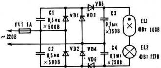
the ir2153 driver is a microcircuit used in pulse converters to power fluorescent lamps, its more modern counterpart is ir2153D and ir2155. In the case of using ir2153D, the VD2 diode can be excluded, since it is already built into the microcircuit. All 2153 series microcircuits already have a built-in 15.6V Zener diode in the power circuit, so you shouldn't bother too much with the device of a separate voltage regulator to power the driver itself;
VD1 - any rectifier with a reverse voltage of at least 400V;
VD2-VD4 - "high-speed", with a short recovery time (no more than 100ns) for example - SF28; In fact, VD3 and VD4 can be excluded, I did not put them;
as VD4, VD5 - a dual diode from a computer power supply unit "S16C40" is used - this is a "Schottky" diode, you can put any other less powerful one. This winding is needed to power the ir2153 driver after the pulse converter starts. You can exclude both diodes and the winding if you do not plan to remove power more than 150W;
Diodes VD7-VD10 - powerful Schottky diodes, for a voltage of at least 100V and a current of at least 10 A, for example - MBR10100, or others;
transistors VT1, VT2 - any powerful field-effect, the output depends on their power, but you shouldn't get too carried away here, as well as remove more than 300W from the unit;
L3 - wound on a ferrite core and contains 4-5 turns of 0.7mm wire; This chain (L3, C15, R8) can be eliminated altogether, it is needed to slightly facilitate the operation of the transistors;
The L4 choke is wound on a ring from the old group stabilization choke of the same power supply from the computer, and contains 20 turns, wound with a double wire.
Capacitors at the input can be supplied with a smaller capacity, their capacity can be approximately selected based on the power taken from the power supply, approximately as 1-2 μF per 1 W of power. You should not get carried away with capacitors and put more than 10,000 uF on the output of the power supply, as this can lead to a "salute" when turned on, since they require a significant current to charge when turned on.
Now a few words about the transformer. The parameters of the pulse transformer are determined in the Moskatov program and correspond to the W-shaped core with the following data: S0 \u003d 1.68 sq. Cm; Sc \u003d 1.44 sq. Cm; Lsr.l. \u003d 86cm; Conversion frequency - 100 kHz;
The resulting calculated data:
Winding 1 - 27 turns 0.90mm; voltage - 155V; Coiled in 2 layers with a wire consisting of 2 cores of 0.45 mm each; The first layer - the inner one contains 14 turns, the second layer - the outer one contains 13 turns;
winding 2 - 2 halves of 3 turns with 0.5mm wire; this is a "self-supply winding" for a voltage of about 16V, wound with a wire so that the winding directions are in different directions, the middle point is brought out and connected to the board;
winding 3 - 2 halves of 7 turns, wound in the same way with a stranded wire, first - one half in one direction, then through the insulation layer - the second half, in the opposite direction. The ends of the windings are brought out in a "braid" and are connected to a common point on the board. The winding is designed for a voltage of about 40V.
In the same way, you can calculate the transformer for any desired voltage. I have assembled 2 such power supplies, one for an amplifier on the TDA7293, the second for 12V to power all sorts of handicrafts, is used as a laboratory one.
Power supply for an amplifier for a voltage of 2x40V:
Switching power supply for 12V:
Power supply assembly in case:
Photo of tests of a switching power supply, - that for an amplifier using a load equivalent from several MLT-2 resistors of 10 Ohm, switched on in a different sequence. The goal was to obtain data on power, voltage drop and voltage difference across the arms +/- 40V. As a result, I got the following parameters:
Power - about 200W (I did not try to shoot anymore);
voltage, depending on the load - 37.9-40.1V in the entire range from 0 to 200W
Temperature at maximum power 200W after a test run for half an hour:
transformer - about 70 degrees Celsius, radiator of diodes without active blowing - about 90 degrees Celsius. With active airflow - it quickly approaches room temperature and practically does not get warm. As a result, the radiator was replaced, and in the following photos, the power supply is already with a different radiator.
When developing the power supply, materials from the site vegalab and radiokot were used, this power supply is described in great detail on the Vega forum, there are also options for a block with short circuit protection, which is not bad. For example, in case of an accidental short circuit, the track on the board in the secondary circuit instantly burned out
Attention!
The first switching on of the power supply should be done through an incandescent lamp with a power of no more than 40W. When you first turn on the network, it should flash for a short time and go out. It practically shouldn't glow! In this case, you can check the output voltages and try to load the unit lightly (no more than 20W!). If everything is in order, you can remove the light bulb and start testing.