We offer two options for connecting fluorescent lamps, without using a choke.
Option 1.
All fluorescent luminaires powered by an alternating current (except for luminaires with high-frequency converters) emit a pulsating (with a frequency of 100 pulsations per second) luminous flux. This has a tiring effect on people's vision, distorts the perception of rotating nodes in mechanisms.
The proposed luminaire is assembled according to the well-known rectified current power supply scheme for a fluorescent lamp, characterized by the introduction of a K50-7 high-capacity capacitor into it to smooth out pulsations.
When you press the common button (see diagram 1), a 5V1 pushbutton switch is triggered, connecting the lamp to the mains, and a 5V2 button, which closes the glow circuit of the LD40 fluorescent lamp with its contacts. When the keys are released, the 5B1 switch remains on, and the SB2 button opens its contacts, and the lamp ignites from the emerging EMF of self-induction. When the button is pressed again, the switch SВ1 opens its contacts, and the lamp goes out.
I do not give a description of the switching device because of its simplicity. To ensure uniform wear of the lamp filaments, the polarity of its switching on should be changed after about 6000 hours of operation. The luminous flux emitted by the lamp has practically no pulsations.
Scheme 1. Connections of a fluorescent lamp with a burnt filament (option 1.)
Even lamps with one burned-out filament can be used in such a lamp. To do this, its leads are closed on the base with a spring made of a thin steel string, and the lamp is inserted into the lamp so that a "plus" of the rectified voltage (the upper thread in the diagram) is applied to the closed legs.
Instead of a capacitor of the KSO-12 brand of 10,000 pF, 1000 V, a capacitor from a failed starter for LDS can be used.
Option 2.
The main reason for the failure of fluorescent lamps is the same as for incandescent lamps - the burnout of the filament. For a standard luminaire, a fluorescent lamp with this kind of malfunction is, of course, unusable and must be thrown away. Meanwhile, according to other parameters, the resource of a lamp with a burned-out filament often remains far from exhausted.
One of the ways to "reanimate" fluorescent lamps is the use of cold (instant) ignition. For this, at least one of the cathodes must be
get along with emission activity (see the scheme that implements the specified method).
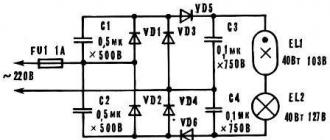
The device is a diode-capacitor multiplier with a factor of 4 (see diagram 2). The load is a circuit of a series-connected gas discharge lamp and an incandescent lamp. Their powers are the same (40 W), the nominal supply voltages are also close in magnitude (103 and 127 V, respectively). Initially, when a 220 V AC voltage is applied, the device works as a multiplier. As a result, a high voltage is applied to the lamp, which provides a "cold" ignition.

Scheme 2. Another option for connecting a fluorescent lamp with a burnt-out filament.
After the occurrence of a stable glow discharge, the device switches to the mode of a full-wave rectifier loaded with an active resistance. The effective voltage at the output of the bridge circuit is practically equal to the mains voltage. It is distributed between lamps E1.1 and E1.2. An incandescent lamp functions as a current-limiting resistor (ballast) and at the same time it is used as a lighting lamp, which increases the efficiency of the installation.
Note that the fluorescent lamp is actually a kind of powerful zener diode, so that changes in the supply voltage value affect mainly the glow (brightness) of the incandescent lamp. Therefore, when the mains voltage is characterized by increased instability, the E1_2 lamp must be taken with a power of 100 W for a voltage of 220 V.
The combined use of two different types of light sources, complementing each other, leads to an improvement in the lighting characteristics: the pulsations of the luminous flux are reduced, the spectral composition of the radiation is closer to natural.
The device does not exclude the possibility of using it as a ballast and a typical choke. It is connected in series at the input of the diode bridge, for example, in an open circuit instead of a fuse. When replacing the D226 diodes with more powerful ones - the KD202 series or the KD205 and KTs402 (KTs405) blocks, the multiplier allows you to power fluorescent lamps with a power of 65 and 80 W.
A properly assembled device does not require adjustment. In the case of a fuzzy ignition of a glow discharge, or in the absence of one at all, at the nominal mains voltage, the polarity of the fluorescent lamp connection should be changed. It is first necessary to make a selection of burned out lamps to identify the possibility of working in this lamp.
Recently I looked at a whole box of burned-out energy-saving lamps, mostly with good electronics, but burned-out filaments of a fluorescent lamp, and I thought - we need to apply all this stuff somewhere. As you know, LDS with burned-out filaments must be fed with rectified mains current using a starless starter device. In this case, the filaments of the lamp are shunted with a jumper and to which high voltage is applied to turn on the lamp. There is an instant cold ignition of the lamp, a sharp increase in the voltage across it, when starting without preheating the electrodes.
And although ignition with cold electrodes is for a more difficult mode than switching on in the usual way, this method allows the use of a fluorescent lamp for lighting for a long time. As you know, the ignition of a lamp with cold electrodes requires an increased voltage of up to 400 ... 600 V. This is implemented by a simple rectifier, the output voltage of which will be almost twice as high as the input mains 220V. An ordinary low-power incandescent light bulb is installed as a ballast, and although the use of a lamp instead of a choke reduces the efficiency of such a lamp, if you use an incandescent lamp for a voltage of 127 V and connect it to the DC circuit in series with the lamp, then we will have sufficient brightness.

Any rectifier diodes, for a voltage of 400V and a current of 1A, you can also use Soviet brown KTs-shki. Capacitors also have an operating voltage of at least 400V.

This device works as a voltage doubler, the output voltage of which is applied to the cathode - the LDS anode. After lighting the lamp, the device switches to the half-wave rectification mode with an active load and the voltage is equally distributed between the EL1 and EL2 lamps, which is true for LDS with a power of 30 - 80 W, having an average operating voltage of about 100 V. When the circuit is switched on this way, the luminous flux incandescent lamps will account for about a quarter of the LDS flux.

For a 40 W fluorescent lamp, a 60 W, 127 V incandescent lamp is required. Its luminous flux will be 20% of the LDS flux. And for a 30 W LDS, you can use two 127 V incandescent lamps of 25 W each, connecting them in parallel. The luminous flux of these two incandescent lamps is about 17% of the LDS luminous flux. Such an increase in the luminous flux of an incandescent lamp in a combined luminaire is explained by the fact that they operate at a voltage close to the nominal, when their luminous flux approaches 100%. At the same time, when the voltage across the incandescent lamp is about 50% of the nominal, their luminous flux is only 6.5%, and the power consumption is 34% of the nominal.
Fluorescent lamps from the very first issues and partially still are ignited with the help of electromagnetic control gear - EMPRA. The classic version of the lamp is made in the form of a sealed glass tube with pins at the ends.
What fluorescent lamps look like
Inside, it is filled with an inert gas with mercury vapor. Its installation is carried out in cartridges through which voltage is applied to the electrodes. An electrical discharge is created between them, causing an ultraviolet glow, which acts on the phosphor layer deposited on the inner surface of the glass tube. The result is a bright glow. The switching circuit of fluorescent lamps (LL) is provided by two main elements: an electromagnetic ballast L1 and a glow discharge lamp SF1.

Switching circuit of LL with electromagnetic choke and starter
Ignition circuits with electronic ballasts
A device with a choke and starter works according to the following principle:
- Voltage supply to electrodes. At first, the current does not pass through the gas medium of the lamp due to its high resistance. It enters through the starter (St) (Fig. Below), in which a glow discharge is formed. In this case, a current passes through the spirals of the electrodes (2) and begins to heat them.
- The starter contacts are heated, and one of them closes, since it is made of bimetal. The current flows through them and the discharge stops.
- The starter contacts stop heating up, and after cooling down, the bimetallic contact opens again. A voltage pulse arises in the choke (D) due to self-induction, which is sufficient to ignite the LL.
- A current passes through the gas medium of the lamp; after starting the lamp, it decreases along with the voltage drop across the choke. At the same time, the starter remains disconnected, since this current is not enough to start it.

Fluorescent lamp switching circuit
Capacitors (C 1) and (C 2) in the circuit are designed to reduce the noise level. The capacitance (C1), connected in parallel with the lamp, helps to reduce the amplitude of the voltage pulse and increase its duration. As a result, the service life of the starter and LL is increased. The capacitor (C 2) at the input provides a significant reduction in the reactive component of the load (cos φ increases from 0.6 to 0.9).
If you know how to connect a fluorescent lamp with burned-out filaments, it can be used in an EMPRA circuit after a slight change in the circuit itself. For this, the spirals are short-circuited and a capacitor is connected in series to the starter. According to this scheme, the light source can work for some more time.
The widespread method of switching on with one choke and two fluorescent lamps.

Switching on two fluorescent lamps with a common choke
2 lamps are connected in series with each other and the choke. Each of them requires the installation of a parallel connected starter. For this, one output pin is used at the ends of the lamp.
For LL, it is necessary to use special switches so that they do not stick contacts from a high inrush current.
Ignition without electromagnetic ballast
To extend the life of burnt out fluorescent lamps, you can install one of the switching circuits without a choke and a starter. For this, voltage multipliers are used.

Diagram of switching on fluorescent lamps without a choke
The filaments are short-circuited and voltage applied to the circuit. After straightening, it increases 2 times, and this is enough for the lamp to light up. Capacitors (C 1), (C 2) are selected for a voltage of 600 V, and (C 3), (C 4) - under 1000 V.
The method is also suitable for serviceable LLs, but they should not work with DC power supply. After a while, mercury collects around one of the electrodes, and the brightness decreases. To restore it, you need to turn the lamp over, thereby changing the polarity.
Connection without starter
The use of a starter increases the lamp warm-up time. Moreover, its service life is short. The electrodes can be heated without it if secondary transformer windings are installed for this.

Connection diagram of a fluorescent lamp without a starter
Where a starter is not used, the lamp has a quick start designation - RS. If you install such a lamp with a starter start, the spirals can quickly burn out, since they have a longer warm-up time.
Electronic ballast
The electronic control circuit of the electronic ballast replaced the old daylight sources to eliminate their inherent shortcomings. The electromagnetic ballast consumes excess energy, often makes noise, breaks down and at the same time spoils the lamp. In addition, the lamps flicker due to the low frequency of the supply voltage.
Electronic ballast is an electronic unit that takes up little space. Fluorescent lights start up quickly and easily without generating noise and providing even illumination. The circuit provides several ways to protect the lamp, which increases the service life and makes it safer to work.
Electronic ballast works as follows:
- Heating of the LL electrodes. Start-up is quick and smooth to extend lamp life.
- Ignition is the generation of a high voltage pulse that breaks through the gas in the flask.
- Combustion - maintaining a low voltage on the lamp electrodes, which is sufficient for a stable process.

Electronic choke circuit
First, the alternating voltage is rectified using a diode bridge and smoothed by a capacitor (C 2). Next, a half-bridge high-frequency voltage generator on two transistors is installed. The load is a toroidal transformer with windings (W1), (W2), (W3), two of them are connected in antiphase. They alternately open the transistor keys. The third winding (W3) supplies the resonant voltage to the LL.
A capacitor (C 4) is connected in parallel to the lamp. The resonant voltage is applied to the electrodes and breaks through the gas medium. By this time, the filaments have already warmed up. After ignition, the resistance of the lamp drops sharply, causing the voltage to drop sufficiently to sustain combustion. The starting process takes less than 1 second.
Electronic circuits have the following advantages:
- start with any given time delay;
- no need to install a starter and massive choke;
- the lamp does not blink or hum;
- high-quality light output;
- compactness of the device.
The use of electronic ballasts makes it possible to install it in the lamp base, which was also reduced to the size of an incandescent lamp. This gave rise to new energy saving lamps that can be screwed into a common standard socket.
During use, fluorescent lamps age and require an increase in operating voltage. In the EMPRA circuit, the glow discharge ignition voltage at the starter decreases. In this case, its electrodes may open, which will cause the starter to operate and turn off the LL. Then it starts up again. Such flashing of the lamp leads to its failure along with the choke. In the electronic ballast circuit, this phenomenon does not occur, since the electronic ballast automatically adjusts to the change in the lamp parameters, choosing a favorable mode for it.
Lamp repair. Video
Tips for fluorescent lamp repair can be obtained from this video.
LL devices and their switching circuits are constantly developing in the direction of improving technical characteristics. It is important to be able to select suitable models and operate them correctly.
Fluorescent lamps (LDS) are the first economical devices that appeared after traditional lamps with incandescent filament. They relate to gas-discharge devices, where an element that limits the power in the electrical circuit is required.
Choke assignment
The fluorescent light choke controls the voltage applied to the lamp electrodes. In addition, it has the following purposes:
- protection against power surges;
- heating the cathodes;
- creating a high voltage to start the lamp;
- limiting the strength of the electric current after starting;
- stabilization of the lamp burning process.
To save money, the choke is connected to two lamps.
The principle of operation of an electromagnetic ballast (EMPRA)
The first one, which was created and is still used today, includes the elements:
- throttle;
- starter;
- two capacitors.
The fluorescent lamp circuit with a choke is connected to a 220 V network. All parts connected together are called electromagnetic ballast.
When power is applied, the circuit of the tungsten spirals of the lamp is closed, and the starter is turned on in the glow discharge mode. The current does not pass through the lamp yet. The threads are gradually warming up. The starter contacts are initially open. One of them is bimetallic. It bends when heated from a glow discharge and completes the circuit. In this case, the current increases by 2-3 times and the cathodes of the lamp are heated.
As soon as the contacts of the starter are closed, the discharge in it stops and begins to cool down. As a result, the movable contact opens and self-induction of the choke occurs in the form of a significant voltage pulse. It is enough for the electrons to penetrate the gaseous medium between the electrodes and the lamp ignites. The rated current begins to pass through it, which then decreases by 2 times due to the voltage drop across the inductor. The starter permanently remains off (contacts open) while the LDS is on.
Thus, the ballast starts the lamp and further maintains it in an active state.

Advantages and disadvantages of EMPRA
The electromagnetic choke for fluorescent lamps features low price, simple design, and high reliability.
In addition, there are disadvantages:
- pulsating light leading to eye strain;
- up to 15% electricity is lost;
- noises at the time of start-up and during operation;
- the lamp does not start well at low temperatures;
- large size and weight;
- long lamp start.
Usually the buzzing and flickering of the lamp occurs when the power supply is unstable. Ballasts are produced with different noise levels. To reduce it, you can choose a suitable model.
Lamps and chokes are matched to each other in terms of power, otherwise the life of the luminaire will be significantly reduced. Usually they are supplied in a set, and the ballast is replaced with a device with the same parameters.
Complete with EMPRAs are inexpensive and do not require adjustment.
The ballast is characterized by the consumption of reactive energy. To reduce losses, a capacitor is connected in parallel with the power supply.

Electronic ballast
All the disadvantages of the electromagnetic choke had to be eliminated, and as a result of research, an electronic choke for fluorescent lamps (ECG) was created. The circuit is a single unit that starts and maintains the combustion process by forming a given sequence of voltage changes. You can connect it using the instructions supplied with the model.
The choke for fluorescent lamps of electronic type has advantages:
- the ability to start instantly or with any delay;
- lack of a starter;
- lack of blinking;
- increased light output;
- compactness and lightness of the device;
- optimal operating modes.
Electronic ballasts are more expensive than electromagnetic devices due to the complex electronic circuitry that includes filters, power factor correction, inverter and ballast. In some models, protection against erroneous starting of the luminaire without lamps is installed.
User reviews say about the convenience of using electronic ballasts in energy-saving LDS, which are built directly into the bases for conventional standard cartridges.

How to start a fluorescent lamp using electronic ballasts?
When switched on, voltage is applied to the electrodes from the electronic ballast, and they are heated. Then they receive a powerful pulse that ignites the lamp. It is formed by creating an oscillatory circuit entering resonance before the discharge. In this way, the cathodes are well heated, all the mercury in the bulb evaporates, due to which the lamp starts up easily. After the discharge occurs, the resonance of the oscillating circuit immediately stops and the voltage drops to the working one.
The principle of operation of the electronic ballast is similar to the version with an electromagnetic choke, since the lamp starts up, which then decreases to a constant value and maintains the discharge in the lamp.
The current frequency reaches 20-60 kHz, due to which flicker is excluded, and the efficiency becomes higher. Reviews often suggest replacing electromagnetic chokes with electronic ones. It is important that they are suitable in terms of power. The circuit can create an instant start or a gradual increase in brightness. It is convenient to make a cold start, but the service life of the lamp becomes much shorter.

Daytime running light without starter, throttle
LDS can be turned on without a bulky choke, using a simple incandescent lamp with a similar power instead. In this scheme, a starter is also not needed.
The connection is made through a rectifier in which the voltage is doubled using capacitors and ignites the lamp without heating the cathodes. In series with the LDS through the phase wire, an incandescent lamp is turned on, limiting the current. Capacitors and diodes of the rectifier bridge should be selected with a margin of allowable voltage. When the LDS is fed through a rectifier, the flask on one side will soon begin to darken. In this case, the polarity of the power supply must be reversed.
Daylight without a choke, where an active load is used instead, gives a weak brightness.
If you install a choke instead of an incandescent lamp, the lamp will glow much stronger.

Checking throttle serviceability
When the LDS is off, the reason lies in a malfunction of the electrical wiring, the lamp itself, the starter or the choke. Simple reasons are identified by the tester. Before checking the fluorescent lamp choke with a multimeter, disconnect the voltage and discharge the capacitors. Then the switch of the device is set to the continuity mode or to the minimum resistance measurement limit and the following are determined:
- the integrity of the coil winding;
- electrical resistance of the winding;
- turn-to-turn closure;
- open circuit in the coil winding.
The reviews suggest checking the choke by connecting it to the network through an incandescent lamp. When it burns brightly, and a serviceable one is full of heat.
If a malfunction is found, the throttle is easier to replace as repairs can be more expensive.
Most often, the starter fails in the circuit. To check its performance, a known good is connected instead of it. If the lamp still does not light up, then the reason is different.
The choke is also checked using a working lamp by connecting two wires from it to its base. If the lamp lights up brightly, then the choke is operational.
Conclusion
The fluorescent light choke is being improved in the direction of improving technical characteristics. Electronic devices are beginning to supplant electromagnetic ones. At the same time, the old versions of the models continue to be used due to their simplicity and low price. It is necessary to understand all the variety of types, properly operate and connect them.
A fluorescent lamp is a light source where the glow is achieved by creating an electric discharge in an inert gas and mercury vapor. As a result of the reaction, an ultraviolet glow, imperceptible to the eye, appears, affecting the phosphor layer on the inner surface of the glass bulb. The standard connection diagram for a fluorescent lamp is a device with an electromagnetic balance (EMPRA).
Fluorescent lamp device
Most bulbs have a cylinder-shaped bulb. There are more complex geometric shapes. At the ends of the lamp there are electrodes resembling the spiral structure of incandescent bulbs. The electrodes are made of tungsten and are soldered to the outside pins. Voltage is applied to these pins.

A gaseous medium is created inside the fluorescent lamp, which is characterized by negative resistance, which manifests itself when the voltage between the electrodes located opposite each other decreases.
In the lamp switching circuit, a choke (ballast) is used. Its task is to form a significant voltage pulse, due to which the light bulb turns on. The kit includes a starter, which is a glow discharge lamp with a pair of electrodes in an inert atmosphere. One of the electrodes is a bimetallic plate. In the off state, the electrodes of the fluorescent lamp are open.
The figure below shows a diagram of the operation of a fluorescent lamp.

How a fluorescent lamp works
The principles of operation of fluorescent light sources are based on the following provisions:
- Voltage is directed to the circuit. However, at first, the current does not reach the light bulb due to the high voltage of the environment. The current moves along the spirals of the diodes, gradually heating them. The current is supplied to the starter, where the voltage is sufficient for the appearance of a glow discharge.
- As a result of heating the contacts of the starter with a current, the bimetallic plate closes. The metal takes over the functions of a conductor, the discharge is completed.
- The temperature in the bimetallic conductor drops, the contact in the network opens. The inductor generates a high voltage pulse as a result of self-induction. As a result, a fluorescent lamp comes on.
- A current flows through the lighting device, which is halved, as the voltage across the inductor is reduced. It is not enough for another start of the starter, the contacts of which are in the open state when the light is on.
To draw up a circuit for switching on two lamps installed in one lighting device, a common choke is needed. The lamps are connected in series, but each light source has a parallel starter.

Connection options
Consider different options for connecting a fluorescent lamp.
Connecting using electromagnetic balance (EmPRA)
The most common type of connection for a fluorescent light source is a circuit with a starter, where an electronic ballast is used. The principle of operation of the circuit is based on the fact that, as a result of connecting the power supply, a discharge occurs in the starter and the bimetallic electrodes are closed.
The current in the electrical circuit of the conductors and the starter is limited only by the internal choke resistance. As a result, the operating current in the bulb increases almost threefold, the electrodes are rapidly heated, and after the loss of temperature by the conductors, self-induction and ignition of the lamp occur.
Disadvantages of the scheme:
- In comparison with other methods, this is a rather costly option in terms of energy consumption.
- Start-up takes at least 1 - 3 seconds (depending on the degree of wear of the light source).
- Inability to work at low air temperatures (for example, in an unheated basement or garage room).
- There is a stroboscopic light bulb flashing effect. This factor has a negative effect on human vision. Such lighting cannot be used for industrial purposes, because fast moving objects (for example, a workpiece in a lathe) seem to be stationary.
- Unpleasant hum of choke plates. As the device wears out, the sound increases.

The switching circuit is designed in such a way that it has one choke for two bulbs. The inductance of the choke should be sufficient for both light sources. 127 Volt starters are used. They are not suitable for a one-lamp circuit; devices for 220 volts are needed there.
The picture below shows the throttle-free connection. There is no starter. The circuit is used in the event of a lamp burnout. A step-up transformer T1 and a capacitor C1 are used, limiting the current flowing through the light bulb from the 220-volt network.

The following circuit is used for light bulbs with burnt filaments. However, there is no need for a step-up transformer, which makes the construction of the device simpler.
![]()
Below is a way to use a diode rectifier bridge, which eliminates the flickering of the light bulb.

The figure below shows the same technique, but in a more complex execution.

Two tubes and two chokes
To connect a fluorescent lamp, you can use a serial connection:
- The phase from the wiring is directed to the choke input.
- From the throttle output, the phase goes to the contact of the light source (1). From the second contact goes to the starter (1).
- From the starter (1) goes to the second contact pair of the same light bulb (1). The remaining contact is mated to zero (N).
The second tube is connected in the same way. First the throttle, then one contact of the light bulb (2). The second contact of the group is directed to the second starter. The starter output is combined with the second pair of light source contacts (2). The remaining contact should be connected to input zero.

Wiring diagram for two lamps from one choke
The scheme provides for the presence of two starters and one choke. The most expensive element of the scheme - the throttle. A more economical option is a two-lamp luminaire with a choke. To learn how to implement the scheme described in the video.
The disadvantages of the electronic ballast circuit caused the need to find a more optimal connection method. During the survey, a method was invented with the participation of electronic ballast. In this case, not the mains frequency (50 Hz), but high frequencies (20 - 60 kHz) are used. It is possible to get rid of blinking light harmful to the eyes.
Externally, the electronic ballast is a block with terminals brought out to the outside. The inside of the device contains a printed circuit board from which you can assemble the entire circuit. The unit is small in size, due to which it fits into the case of even a small lighting device. Switching on is much faster compared to the ECG standard. The operation of the device does not cause acoustic discomfort. This method of connection is called starless.
It is not difficult to understand the principle of operation of a device of this type, since there is a circuit on its back side. It shows the number of lamps for connection and explanatory labels. There is information about the power of the lamps and other technical parameters of the device.

The connection is carried out as follows:
- The first and second contacts are connected to a pair of lamp contacts.
- The third and fourth contacts are directed to the remaining pair.
- The input is powered.
Using voltage multipliers
This option allows you to connect a fluorescent lamp without using an electromagnetic balance. It is usually used to increase the life of light bulbs. The connection diagram of the burned-out lamps makes it possible for the light sources to work for some more time, provided that their power is no more than 20 - 40 W. The filaments are allowed both suitable for work and burned out. In any case, the leads must be short-circuited.

As a result of rectification, the voltage doubles, so the light turns on almost instantly. Capacitors C1 and C2 are selected based on an operating voltage of 600 volts. The disadvantage of capacitors is their large size. As capacitors C3 and C4, preference is given to mica devices for 1000 volts.
Fluorescent lamps are not DC compatible. Very soon, so much mercury accumulates in the device that the light becomes noticeably weaker. To restore the brightness of the glow, reverse the polarity by turning the bulb over. Alternatively, you can install a switch to avoid removing the lamp every time.
Connection without starter
The method using a starter is associated with prolonged heating of the bulb. In addition, this part must be changed frequently. A circuit where the electrodes are heated using old transformer windings allows to do without a starter. The transformer acts as a ballast.

Bulbs used without a starter must bear the inscription RS (quick start). A light source with a start through a starter is not suitable, since its conductors heat up for a long time, and the spirals quickly burn out.
Serial connection of two bulbs
In this case, it is necessary to connect two fluorescent lamps with one ballast. All devices are connected in a serial manner.
To carry out electrical work, you will need the following details:
- induction choke;
- starters (2 units);
- fluorescent bulbs.
Connection is made in the following order:
- We attach starters to each light bulb. We connect in parallel. The junction is a pin input at the ends of the lighting device.
- We send free contacts to the electrical network. We use a choke for connection.
- We connect capacitors to the contacts of the light source. Will reduce the intensity of interference in the network and compensate for power reactivity.
Note! In standard household switches (especially in inexpensive models), contacts often stick due to too high starting currents. In this regard, it is recommended to purchase high-quality switches for use in conjunction with fluorescent lamps.

Replacing the Lamp
If there is no light and the cause of the problem is only to replace a burnt out light bulb, proceed as follows:
- We disassemble the lamp. We do this carefully so as not to damage the device. We turn the tube along the axis. The direction of travel is indicated on the arrow-shaped holders.
- When the tube is turned 90 degrees, lower it down. The contacts should come out through the holes in the holders.
- The contacts of the new bulb must be in a vertical plane and fall into the hole. When the lamp is installed, we turn the tube in the opposite direction. It remains only to turn on the power supply and check the system for operation.
- The final action is the installation of a diffusing plafond.
System health check
After connecting the fluorescent lamp, you should make sure that it is working and that the ballasts are in good working order. For testing, you will need a tester with which to check the cathode filaments. The allowed resistance level is 10 ohms.
If the tester detects the resistance as infinite, it is not necessary to discard the bulb. This light source still retains functionality, but it must be used in cold start mode. In the normal state, the starter contacts are open, and its capacitor does not pass direct current. In other words, the ringing should show a very high resistance, which sometimes reaches hundreds of ohms.
After touching the throttle leads with the ohmmeter probes, the resistance gradually decreases to a constant value inherent in the winding (several tens of ohms).
Note! A faulty condition of the throttle is indicated by the burnout of a recently supplied light bulb.

It will not be possible to reliably determine the turn-to-turn circuit in the choke winding using a conventional ohmmeter. However, if the instrument has an inductance measurement function and ECG data, a mismatch will indicate a problem.