Stroboscopes are used on cars to adjust the ignition system of the power unit. This device can be purchased at any auto store. But the device can be made independently. The process of making a stroboscope yourself does not take much time. More on this later in the article.
A stroboscope makes life much easier for its owner.
Thanks to him, even an inexperienced motorist can independently adjust the ignition angle. The stroboscope operation is based on the stroboscopic effect - a moving object is illuminated by a light flash.
It is beneficial to have such a device, since it makes it possible to independently regulate the ignition without contacting a service center, which saves the car owner's time and money. There are motorists who prefer factory strobe lights, not trusting home-made ones, but they are no worse than traditional purchased ones.

Why is it difficult to set the ignition without a stroboscope
It is very difficult to adjust the ignition system with bare hands. The stroboscope allows several times to speed up the time for adjusting the ignition of the vehicle. The light in the lamp of this device signals the formation of a spark, which makes it possible to adjust the correct lead angle.
Factory-made strobe, pros and cons
Factory devices work flawlessly and efficiently, but they cost decently. But in fact, all such devices have an expensive lamp, the failure of which leads to the acquisition of a new device. It is worth noting that even at the service station, some craftsmen use homemade devices.
Top 5 Most Popular Factory-Made Strobe Lights

The most popular factory-made strobe lights are:


The cost of such devices reaches six thousand rubles. If you make a stroboscope yourself, it will cost you about 600-700 rubles. So, saving money actually tenfold stimulates you to make such a device with your own hands.
Spare parts and parts for making a strobe with your own hands
- Diode flashlight.
- Copper wires.
- Capacitors c1.
- Specialized clamps.
- Low frequency diode V2.
- Resistors 0.125 V.
- Thyristor KY112A.
- Relay with index RWH-SH-112D.
- Meter cord.

Such parts and spare parts can be purchased at any electronics store or radio market. The body of the device is small. You can even use the base of an old flashlight.
Stroboscope circuit
There are many schemes on the Internet on how to create a simple stroboscope yourself. Most of them are easily and quickly assembled without requiring significant financial investments.

Assembling a strobe with your own hands, step by step, the easiest option
Sequencing:
- We drill a hole for the power wire.
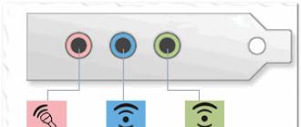
- Observing the polarity, we solder the clips to the ends of the wires.
- The sensor can be installed on the right or left.
- We solder copper wire to the main conductor.
- We isolate all contacts.
This invention is used to test the operation of the regulator and spark plug.
Timer based strobe, pros and cons
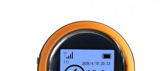
To make a device yourself using a timer, you need to make more effort than for a conventional strobe. The key advantage of such a device is constant light pulses that do not depend on the battery voltage. A stroboscope such as a tachometer is used. To do this, you need to switch the regulator.

LED strobe, pros and cons
The basis of such devices is the 155AG1 microcircuit, which requires pulses with negative polarity to start. In such circuits, it is necessary to use resistances R1, R2, R3. They limit fluctuations in the input signal. This circuit will be powered by a rechargeable battery. The duration of the pulses is able to provide the capacitance C4 with the resistor R6. According to the classic settings, this value will be equal to 2 ms.

How to use homemade strobe lights
For the correct functioning of a homemade device, it must be checked. From the existing device, you need to set the lead angle:
- First, we warm up the power unit and leave it to operate at idle speed.
- We connect the device to the battery.
- We wind the copper sensor onto the core of the cylinder.
- Next, you should orient the light source according to a special pointer on the body.
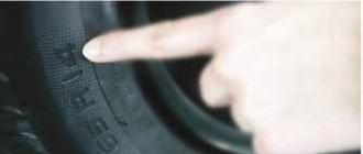
- We look for a fixed point on the flywheel.
- To make the two points match, rotate the ignition housing and store it in the desired position.
The key point in self-manufacturing of this device is the correct assembly of the electrical circuit. That is why, before starting manufacturing, it is imperative that you first make a detailed diagram that will help to avoid mistakes when assembling the device.
Do not forget about safety precautions. Any stroboscope operates under voltage. The internal elements of the device must not be allowed to touch its case, especially the metal one.
It is desirable that the variable resistor is protected with a plastic handle. A well-insulated power cord must have a plug. All parts must be mounted on a special board made of insulating material. Parts are mounted according to a special scheme, but their location is not critical. It is necessary to fasten all elements very carefully.
The process of adjusting the initial ignition moment is greatly simplified using special devices. Their work is based on the stroboscopic effect. The meaning of this physical phenomenon is as follows: if you illuminate a moving object with a short flash of light, then there will be a visual illusion that it has remained in the same position in which this flash caught it.
It is very simple to make a stroboscope on LEDs with your own hands. There are diagrams of simple devices that even an inexperienced radio amateur can repeat.
LED strobe on timer NE555
The main component in this stroboscope circuit is the NE 555 integrated timer. This is a common microcircuit often used in electronic homemade products.
A ready-made assembly of six LEDs from a Chinese flashlight was used as a light emitter.
Stroboscope circuit on timer NE555
Potentiometer P1 sets the pause time between pulses that are applied to VT1. Opening at the moment the signal is applied, the field-effect transistor "lights" the stroboscope.
It should be borne in mind that at the moment of the flash, the current passing through the emitter exceeds two amperes. This circumstance forces the use of a limiting resistor with a dissipation power of at least 2W. There is no cause for concern regarding LED failure. Ultra-short operating time in these modes will not damage semiconductors.
Instead of the transistor indicated in the diagram, you can use its closest analogs: IRFZ44, IRF3205, KP812B1 and others.
The requirements for the VD1 diode are high speed. The 1N4148 is being successfully replaced by the domestic version of the KD522. Any Schottke diode will also work well.
The capacity of the capacitors can be increased by one order of magnitude. This will not affect the performance of the circuit in any way.
This is how the assembled device looks like, with three heavy-duty LEDs.
 Stroboscope assembly
 A small number of parts allows you to make a stroboscope from LEDs by the hinged method or using special mounting panels. If no mistakes are made during the soldering process, the circuit will work immediately, without additional adjustment.
Another variation of the do-it-yourself collection of a car LED strobe is based on the TL494 PWM driver. The cost of the microcircuit lies in the range of 10 - 20 rubles apiece, so you cannot call it a scarce one. In addition, you can remove the required component from an old ATX power supply from a personal computer.
 Diagram of the LED strobe on the TL494 PWM controller
 As in the previous case, the emitter is controlled by a MOSFET transistor. Here it can be of any type that meets two requirements:
- Rated current - from 2A;
- internal structure - N-type.
Examples of suitable field workers: AP15N03GH or IRLZ44NS.
The trimmer resistor VR1 sets the duty cycle (duration of flashes), and VR2 - their frequency. It is more convenient to use potentiometers with a linear relationship, since the adjustment process is much easier to perform.
The light source in this stroboscope circuit is one powerful LED. To connect a 12 volt LED strip, the resistor R6 must be removed by installing a jumper instead.
The rest of the elements of the LED strobe circuit can be any with the indicated ratings.
Device circuit board
You can minimize the size of the structure by using SMD components. Some novice radio amateurs try to avoid using them, believing that the installation of small parts is too laborious. And in vain! A little practice will help you easily cope with this task. But the result will be an excellent reward for your patience.
A sample implementation of the LED strobe circuit board is shown in the figure.
 Sample PCB for strobe
A two-way routing method is used here. Above, large radio elements are installed: a microcircuit, terminal blocks and electrolytic capacitors, below resistors and capacitors of size 1206, LEDs of size 0805, a MOSFET transistor in a DPAK case. The regulating resistors are replaced with trimmer ones. This was done to make the structure smaller.
The appearance of the board of the finished device from both angles is presented below. To transfer a pattern with tracks to foil textolite, the LUT method was used. Etching was carried out in an aqueous solution of ferric chloride.

If you want to repeat the stroboscope circuit on LEDs with your own hands, you can use the project for the Sprint Layot tracer, changing it, if necessary, according to your own needs. ...
The consideration in the article of stroboscope circuits is distinguished by its simplicity and low cost of electronic components. The total cost of materials will cost ten times less if you purchase a ready-made stroboscope with LEDs. In addition, using a home-made device is much more pleasant, and the experience gained in the process of work is irreplaceable and priceless.
To accurately set the ignition on the engine, you must use special devices - stroboscopes. They can be purchased at car dealerships or made by hand. In the second case, you will save a decent amount and make the most suitable device for your car model.
Features of factory strobes and how they work
It is rather difficult to accurately adjust the ignition without using a strobe. Such a device significantly speeds up the tuning process, the lamp signals the appearance of a spark, which allows you to correctly set the ignition timing. Despite the fact that factory instruments work efficiently and accurately, many motorists are in no hurry to buy them. The main limiting factor is the high price of strobe lights. Most models use an expensive gas discharge lamp, replacing it is like buying a new device.
The device itself can be made by hand using simple and affordable materials. There are several good manufacturing schemes that will help you save money on buying factory analogues. For example, you can see the prices for the most popular strobe lights that are on sale:
- Multitronics C2 - 900-1000 rubles.
- AstroL5 - 1300 rubles.
- Focus F1 - 1700 rubles.
- Focus F10 - 5600 rubles.
Homemade devices are made from flashlights, LEDs, or a laser pointer. At a low cost (about 500 rubles), the device will work no less reliably and efficiently.
Instructions for the manufacture of a device for installing ignition
The easy way
There are many different schemes on the network, almost all of them are easy to assemble and do not require large expenditures on materials. Consider one of the most popular schemes for creating a strobe at home. From the details we need:
- transistor KT315;
- thyristor KU112A, resistors 0.125 W;
- any flashlight on diodes (diodes should be 6 or more);
- capacitors C1;
- low frequency diode V2;
- relay with index RWH-SH-112D;
- power cord 1 meter long;
- special clamps;
- copper wire about 10 cm.
All parts can be purchased at the radio market or in a specialized store. An old flashlight or a flash from a camera can be used as a housing for the device.

Assembly diagram of a car stroboscope in a case from an old flashlight

You can use such a device not only for installing the ignition. They can check the candle, adjust the operation of the regulator.
Homemade pribluda using a timer
A stroboscope based on timer devices has a more complex circuit. Its main advantage is stable light pulses that are independent of the battery voltage. The device can also work in the tachometer mode, for this you just need to change the position of the regulator.

Timed strobes can also be used as a tachometer
Tip: It is better to use diodes from the KD521 series in the circuit. If you have not found a domestic-made timer, you can take a foreign analogue of NE555.
Diagram of the device manufacturing on LEDs
This device is based on the 155AG1 microcircuit, it is triggered by pulses with negative polarity. The circuit uses resistances R1, R2, R3, which limit the amplitude of the input signal. The required pulse duration is set by the capacitance C4 and the resistor R6. With standard settings, this is 2 ms. The vehicle battery will be used as a power source.

LED strobe lights are highly reliable and can be used even in bright daylight
Video: how to make a stroboscope with your own hands
How to set up a homemade product correctly
To test the device in practice and set the ignition timing, do the following:
- We warm up the engine and leave it to idle.
- We connect a homemade stroboscope to a power source.
- We wind the copper sensor around the core of the first cylinder.
- We direct the light source to a special mark, which is applied to the body.
- Find a fixed point on the flywheel pulley.
- In order for the two points to converge, it is necessary to rotate the ignition housing and then fix it in a certain position.
In practice, homemade strobe lights are in no way inferior to factory ones. The main thing is to correctly assemble the circuit and check the operation of the device. Homemade strobe lights are inexpensive and can be easily repaired if necessary.
A stroboscope is a very familiar device that has found wide application in many branches of science and technology. A simple example of a stroboscope is police flashers. Such flashers are considered a special signal and their use is illegal. Despite this, some adventurers who are looking for adventure on their own are used to using illegal to distinguish themselves from others. To be honest, I consider myself one of them, so I decided to make a "MENTOV" stroboscope with my own hands and share the diagram with you.
LED strobe circuit
Of all the schemes that can be found on the Internet, this the simplest and most fully working... Let me remind you that such a strobe differs from a simple flasher in that there is you can set the flashing frequency and the number of LED flashes. Simply put, each LED blinks 2, 3 (up to 4 times is possible) then switches and the second LED starts blinking. It turns out a complete analogue of police stroboscopes, which are best used in the wilderness of your area, otherwise you will face a round fine for using a special signal.

The stroboscope circuit does not contain MK. The master generator is everyone's favorite 555 timer. The CD4017 counter has a domestic counterpart (K561IE8). It is a decimal divisor counter with 10 decrypted outputs.
The signal from the outputs of the microcircuit is amplified by transistor switches, here the choice is very large. If you are going to connect LEDs, you can exclude transistors altogether; to power more powerful LEDs or LED assemblies, you can use any bipolar LF transistors - KT819 / 805/805/829, etc.

More powerful lamps can be connected to the stroboscope, for example, halogen lamps from car headlights with a power of 100 or more watts. To do this, you only need to use powerful field switches IRFZ44, IRF3205, IRL3705, IRF1405 and other N-channel power transistors of appropriate power.
The installation of the stroboscope was done in a housing from an electronic transformer, the housing simultaneously serves as a heat sink for transistors, although overheating is not observed on them.

Such a homemade stroboscope can work for hours, the circuit does not need additional adjustment and works immediately after switching on. The device is powered by a 12 Volt vehicle electrical system, although it starts working from 6 Volts.
Video of the homemade stroboscope:
A very powerful LED strobe that will perfectly complement any disco dance floor. A stroboscope was built on three LED matrices with a total power of 150 W.
The principle of operation of the device is to give very short pulses of light (flashes) after a given period of time. The action is very similar to lightning in the rain, when a completely dark room is illuminated by a bright light for milliseconds.
During a disco, it looks especially mesmerizing.
Details:
- LED Matrix -
- 12V source -
- Transistor K2543 -
- Diode bridge -
- Chip NE555 -
- Resistors and Capacitors -

Stroboscope circuit

I would not say that the scheme is complex, rather simple. But it does not have a galvanic voltage isolation, which means that you must not touch any elements of the circuit during its operation and be especially careful during assembly.
Visually, the circuit can be divided into a 12V power supply, a pulse generator, a rectifier and a line of LEDs.
Strobe operation
A short pulse generator is assembled on the NE555 microcircuit. The time between pulses can be changed by rotating the knob of the variable resistor R3.A field-effect transistor switch is connected to the output of this generator, which switches the voltage of 220 V in the power supply circuit of LED matrices connected in parallel to each other.
LED arrays are powered by direct current, which is rectified by a diode bridge. This is necessary in order to be able to switch the circuit with a field-effect transistor, which works only with constant voltage.

Assembling the strobe
The stroboscope is assembled in a casing from the cable channel. The LEDs are screwed to the wide side, no heat sinks. Since the LED is used somewhere at 2-5% of its power (pulse operation), there is no need for heat sinks.
The side walls are cut from the same cable duct and glued with glue. Above, a variable resistor is brought out to adjust the flicker frequency.

Circuit blocks in the case:


Warning
LEDs are very powerful and can damage your eyes, so looking at them while working is not recommended. Strobe flashes are especially dangerous, as the eye relaxes in the dark, and the bright impulse penetrates directly into the retina.Also, do not forget that the entire circuit is under life-threatening mains voltage.
Result of work
Unfortunately, the operation of the stroboscope cannot be conveyed either through photos or videos. Since even a video camera picks up a short impulse very badly and as a result it simply lights up.But from myself I can say that the stroboscope turned out to be excellent, the flashes are short and very bright. It looks very impressive, in general, everything is as it should.