Currently, all mobile devices and desktop electrical appliances have data ports in their arsenal. Modern gadgets can not only exchange information through USB or micro-USB, but also to charge the batteries. In order to carry out a competent pinout of contacts, first you need to study the diagrams and colors of the wiring.
USB cable wire colors
Connector diagram for USB 2.0
On the diagram, you can see several connectors that differ from each other in a certain way. For example, an active (power) device is designated by the letter A, and a passive (connected) device by the letter B. Computers and hosts are active, and printers, scanners and other devices are passive. It is also customary to divide connectors by gender: M (male) or “male” is a plug, and F (female) or “mother” is a connector socket. There are formats in size: mini, micro and unmarked. For example, if you see the designation “ USB micro-VM”, It means that the plug is intended for connection to a passive device in micro format.
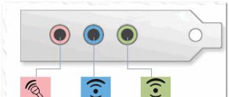
To pinout the sockets and plugs, you need to know about the purpose of the wires in the USB cable:
- the red VBUS ("plus") is a constant voltage of 5 volts relative to GND. The minimum value of the electric current for it is 500 mA;
- connect the white wire to the minus (D-);
- the green wire is attached to the plus (D +);
- black color of the wire means that the voltage in it is 0 Volts, it carries a negative charge and is used for grounding.
In mini and micro formats, the connectors contain five pins: red, black, white and green wires, as well as ID (which is shorted to GND in type A connectors, and is not used at all in connectors B).
Sometimes a bare Shield wire can be found in the USB cable. This wire has no number.
If you use a table in your work, then the connector is shown from the outside (working) side. The insulating parts of the connector are light gray, the metal parts are dark gray, and the cavities are white.
In order to carry out the correct USB wiring, you need to mirror the image of the front of the connector.
The mini and micro USB connectors have five pins. Therefore, the fourth contact in type B connectors will not have to be used in operation. This contact in type A connectors is closed with GND, and for GND itself, the fifth is used.
As a result, not tricky manipulations can be done independently.
Usb wiring version 3.0 differs in the addition of four colored wires and an additional ground. Due to this, the cable USB 3.0 noticeably thicker than its younger brother.
Diagrams for connecting USB devices to each other and wiring device plugs:

Reading circuits: choke, coil, capacitor Convenient fringe cutter for transformers. Soldering iron heating regulator with power indicator Household fan repair Homemade pressure sensor
It has been developed since 1994, while the development team consisted of engineers from leading companies in the field of IT technologies - Microsoft, Apple, Intel and others. In the process of conducting research, one task was pursued - to find a universal port that could be used for most devices.
Thus, users were provided with a USB connector, which was almost immediately supported by various developers and began to be actively used in a wide variety of devices, from personal computers to mobile gadgets. However, it so happened that cables with such connectors could not be used everywhere, and by themselves they were different, and therefore some require the wiring of the mini-USB connector in order to make the appropriate adapter.
At the same time, few people know how this procedure should be carried out correctly.
Concepts to know
Wiring the USB connector begins with learning the basic concepts:
- VCC - positive potential contact For modern USB cables, the indicator of this contact is +5 Volts, while it is worth noting that in radioelectric circuits, this abbreviation fully corresponds to the supply voltage of PNP, as well as NPN transistors.
- GND - contact of the negative potential of the power supply. In modern equipment, including also various models of motherboards, this device is connected by a case in order to provide effective protection against static electricity or any external sources of electromagnetic interference.
- D- - information contact with zero potential, relative to which information is broadcast.
- D + - informational contact with logical unit. This contact is used to broadcast information from the host to the device, or vice versa. At the physical level, this process is the transmission of rectangular pulses with a positive charge, while the pulses have different amplitude and duty cycle.
- Male - the plug of this connector, which is often called "male" among modern users who unsolder the USB connector for mice and other devices.
- Female - The jack where the plug is inserted. The users are called "mom".
- RX - information reception.
- TX - information transfer.
USB-OTG
OTG is a way to connect two peripherals via a USB cable without the need for a computer. Also, such a pinout of the micro-USB connector is often called USB-host in professional circles. In other words, a flash drive or some kind of hard drive can thus be directly connected to a tablet or mobile phone in the same way as to a full-fledged personal computer.

In addition, mice or keyboards can be connected to gadgets if they support the ability to use them. Often, cameras and other gadgets are connected to printers in this way.
What limitations does it have?
The limitations that such a pinout of the micro-USB connector has are as follows:

For example, if we are talking about connecting a USB flash drive to the phone, then the adapter "USB_AF-USB_AM_micro" is most often used. In this case, the USB stick is inserted into the connector, while the plug is connected to the mobile phone.
Cable feature

The main feature that distinguishes the pinout of the USB connector in the OTG format is that in the plug pin 4 must be closed with pin 5. In the standard data cable, nothing is soldered to this pin at all, but this plug is called USB-BM micro. It is for this reason that you need to get to the fourth contact, and then use a jumper to connect it to the GND wire. After this procedure, the plug will be renamed to USB-AM micro. It is the presence of a jumper between these contacts in the plug that allows the device to determine that they are going to connect some kind of peripheral device to it. In the event that the device does not see this jumper, it will act as a passive device, and any flash drives connected to it will simply be completely ignored.
How are devices identified?

Many people believe that when connected in OTG mode, both devices completely automatically determine which of them will be the host and who will be subordinate. In reality, in this case, only the user determines who exactly will be the master in this case, since a plug equipped with a jumper between 4 and 5 contacts will be plugged into which device, then one of them will be the host.
How to do it?
Through the translucent insulation, you can see several different colored wires. You will need to melt the insulation near the black wire, then solder one end of the jumper to the GND pin. On the opposite side, you can see a white wire as well as an unused contact. In this case, we need to melt the insulation near the unused contact, and then solder the other end of the jumper to it.
It is worth noting that the wiring diagram for a micro USB connector is much simpler.
The open plug that you equipped with a jumper will need to be insulated, for which a specialized heat shrink tubing is used. After that, you just need to take the "mother" from the extension cord and solder it to our plug color in color. If the cables are shielded, then you will also need to connect the shields, among other things.
Can i charge?
If peripherals are connected to the device via OTG, then in this case it will have to power it, which can significantly reduce the overall operating time of the device from the battery built into it. In this regard, many are wondering whether it is possible to recharge such a device through an external source. This is possible, but this requires support for a special mode in the device, as well as a separate pinout of the USB connector for charging.

In fact, the charging mode is most often provided by modern gadget developers, but not everyone allows such a procedure. At the same time, it should be noted that to switch to such a charging mode, a separate wiring diagram for the USB connector must be used, in which the contacts are closed through a separate resistor.
Pinout of micro usb charging connector - The USB bus connector appeared around the beginning of the 1990s, and its main purpose was for use in consumer radio equipment. Today, the micro usb connector has become extremely popular not only in consumer devices, but also in professional multimedia devices. However, its "everyday" origins are clearly visible in the fact that these connectors are plug-in format installed on almost any audio-video equipment, without exception.
The first connectors differed from modern ones in their large dimensions, although its socket was normally installed in small-sized portable devices. Over time, the dimensions of USB connectors have taken on compact forms in various variants such as MINI-USB, MICRO-USB and just USB. These types of connecting devices made it possible to carry out its main functional purpose. At the same time, they significantly differed in size and ease of use from the previously created analogue.
The device and pinout of the micro usb connector for charging
The micro usb connecting device also consists of five contact pads, each pad has an insulated mounting wire. For accurate orientation of the connector when connected to the mating part of the connector, a special chamfer is made on the top of its shielding part. Connector pads are numbered from one to five and read from right to left. For clarity, this is shown in the picture below. The scheme for wiring the micro usb connector, as well as the purpose of its contacts isolated from each other, are shown in the table:
Pinout of micro USB by wire color
The shielding also serves as a wire, but is not soldered to a separate contact pad.
Modern connecting devices such as micro usb connectors have fairly good performance and a relatively low price. Therefore, given the presence in the trade of a huge number of various connecting wires of this type, the repair of such auxiliary equipment is extremely rare. But still, if you have to replace a defective connector socket, then pinout of the micro usb connector will not cause much trouble. Constructively well-made micro USB-connectors, even in spite of their miniature dimensions, they will not allow you to make gross mistakes in installation.
A bit of USB history
The development of the Universal Serial Bus, or USB, began in 1994 by Ajay Bhatt, an Indian-born American engineer from Intel, and his USB-IF (USB Implementers Forum, Inc) unit from leading computer companies. The port development company includes representatives from Intel, Compaq, Microsoft, Apple, LSI and Hewlett-Packard. The developers were faced with the task of inventing a universal port for most devices, working according to the Plug & Play principle (Connect and Play), when the device, after connecting to a computer, either started working immediately, or started after installing the necessary software (drivers). The new principle should replace LPT and COM ports, while the data transfer rate should be at least 115 kbps. In addition, the port had to be parallel, in order to organize the connection of several sources to it, as well as to allow the use of connecting devices to "hot" without turning off or restarting the PC.
The first non-industrial USB port, codenamed 1.0, capable of transferring data up to 12 Mbps. was introduced in late 1995 - early 1996. In mid-1998, the port was upgraded with automatic speed control for a stable connection and could operate at a speed of 1.5 Mbps. Its modification became USB 1.1. Since mid-1997, the first motherboards and devices with this connector have been released. In 2000, USB 2.0 appeared, supporting 480 Mbps. The main design principle is the ability to connect to the port of old devices based on USB 1.1. At the same time, the first 8 megabyte flash drive appears for this port. 2008, with improvements to the USB controller in terms of speed and power, was marked by the release of the 3rd version of the port, with support for data transfer at speeds up to 4.8 Gbps.
Basic concepts and abbreviations used for pinout of USB connectors
VCC (Voltage at the Common Collector) or Vbus - contact of the positive potential of the power supply. For USB devices it is +5 Volts. In radioelectric circuits, this abbreviation corresponds to the supply voltage of bipolar NPN and PNP transistors.
GND (Ground) or GND_DRAIN - negative power contact. In hardware (including motherboards), it is connected to the case to protect against static electricity and a source of external electromagnetic interference.
D- (Data -) - information contact with zero potential, relative to which data transfer takes place.
D + (Data +) - information contact with logical "1", necessary for data transfer from the host (PC) to the device and vice versa. Physically, the process is the transmission of positive rectangular pulses of different duty cycle and an amplitude of +5 Volts.

Male - USB connector, popularly referred to as "dad".
Female - USB or female connector socket.
Series A, Series B, mini USB, micro-A, micro-B, USB 3.0 - various modifications of USB device connectors.
RX (receive) - data reception.
TX (transmit) - data transfer.
-StdA_SSRX - negative contact for receiving data in USB 3.0 in SuperSpeed \u200b\u200bmode.
+ StdA_SSRX - positive contact for receiving data in USB 3.0 in SuperSpeed \u200b\u200bmode.
-StdA_SSTX - negative contact for data transfer to USB 3.0 in SuperSpeed \u200b\u200bmode.
+ StdA_SSTX - positive contact for data transfer to USB 3.0 in SuperSpeed \u200b\u200bmode.
DPWR - additional power connector for USB 3.0 devices.
Pinout USB connector
For specifications 1.x and 2.0, the pinout of the USB connector is identical.

As you can see from the figure, there is a supply voltage for the periphery of the connected device on legs 1 and 4, and information data is transmitted via contacts 2 and 3. In the case of using a five-pin micro-USB connector, you should be guided by the following figure.

As you can see, the use of pin 4 is not provided in the standard specification. However, sometimes the 4 pin is used to supply positive power to the device. Most often, these are energy-intensive consumers with a current tending to the maximum allowable for a USB 2.0 connector, which will be discussed below. According to the standard, each wire has its own color. So the positive contact of the power supply is connected with a red wire, the negative contact with black, the data- signal goes on white, and the positive information signal data + on green. In addition, to protect devices from external influences, high-quality cables use shielding of the metal parts of the connectors by closing the outer metallized cable sheath to the case. In other words, the cable shield can be connected to the negative of the connector power supply (but this condition is not required). The use of the shield improves the stability of data transmission, increases the speed and applies a longer cable length to the device.

In the case of using a micro-USB - OTG cable to the tablet, the 4th unused contact is connected to the negative wire. The cable diagram is clearly shown in the picture from w3bsit3-dns.com. In this case, it is strictly forbidden to supply positive power to the 4th pin of the connector, which entails failure of either the USB port controller, or damage to the OTG controller!
As for the USB 2.0 connector specification, the table below shows the main characteristics.
The specification also indicates that for filtering the useful signal, the maximum capacitance between the Data bus and the negative power supply contact (ground) is allowed to use a capacitance of up to 10uF (minimum 1uF). It is not recommended to use a larger capacitor, because at speeds close to the maximum, the pulse edges are delayed, which leads to a loss of the speed characteristics of the USB port.

When connecting external USB connectors to the motherboard, you should pay special attention to the correct connection of the wires, since it is not so scary to confuse the Data - and Data + information signals, as it is dangerous to swap the supply wires. In this case, from the experience of repairing electronic equipment, the connected device more often becomes unusable! The connection diagram must be found in the instructions for the motherboard.
It remains to add that for the implementation of cables for connected devices of the USB 2.0 connector, the standard for the cross-sections of each wire in the cord has been approved.
The AWG is the American wire cross-section marking system.
Now let's move on to the USB 3.0 port
The second name of the USB 3.0 port is USB Super Speed, due to the increased data transfer speed up to 5 Gb / s. To increase the speed indicators, the engineers used full-duplex (two-wire) transmission of both sent and received data. Due to this, 4 additional contacts appeared in the connector - / + StdA_SSRX and - / + StdA_SSTX. In addition, the increased speeds required a new type of controller with higher power consumption, which led to the need for additional power pins in the USB 3.0 connector (DPWR and DGND). The new type of connector became known as USB Powered B. As a digression, let's say that the first Chinese flash drives for this connector were made in cases without taking into account the thermal characteristics of their controllers and, as a result, got very hot and failed.
The practical implementation of the USB 3.0 port made it possible to achieve the data exchange rate at the level of 380MB / sec. For comparison, the SATA II port (connecting hard drives) is capable of transferring data at a speed of 250MB / sec. The use of additional power supply made it possible to use devices with a maximum current consumption of up to 900mA on the socket. So either one device or up to 6 gadgets with a consumption of 150mA can be connected. In this case, the minimum operating voltage of the connected device can be reduced to 4V. Due to the increased power of the connector, the engineers had to limit the length of the USB 3.0 cable to 3m, which is an undoubted disadvantage of this port. Below is the standard USB 3.0 port specification.
The pinout of the USB 3.0 connector is as follows:


Operating system from Windows 8, MacBook Air and MacBook Pro latest versions and Linux from kernel version 2.6.31 have full software support for USB 3.0 specification. Due to the use of two additional power contacts in the USB 3.0 Powered-B connector, it is possible to connect devices with a load capacity of up to 1A.
Universal Serial Bus (USB) wiring diagram
Wiring diagram for USB connectors
Wiring diagram for USB connectors (cable and device)

Wiring diagram for USB connectors (cable and device)
USB signals are transmitted over two wires (twisted pair) of a shielded four-wire cable.
VBUS - voltage +5 Volt of the power circuit, GND - contact for connecting the "body" of the power circuit. The maximum current drawn by the device through the USB bus power lines must not exceed 500 mA. Data is transferred via pins D- and D + of the USB connector. Differential data transfer is basic for USB.
USB cable connectors
For the USB cable, special USB connectors are used. The USB cable is directional, therefore, for correct connection, USB connectors have different configurations. There are two types of USB connectors: Type A (see Fig. 7. and Fig. 8.) and Type B (see Fig. 9., Fig. 10 and Fig. 11).

Fig. 7. Common USB cable connector Type A
In accordance with the 1.0 specification USB Type A connectors are used for connection "to the host" ie. installed on the side of the controller or USB hub.

Fig. 8. "Branded" USB cable connector Type A
In accordance with the 1.0 specification USB Type B connectors are used for connecting "to a device" ie. for connecting peripheral devices.

Fig. 9. A normal USB cable connector Type B. This connector is suitable, for example,
to connect the printer

Fig. 10. Normal USB mini cable Type B

Fig. 11. Micro USB cable connector Type B. In the figure below the USB symbol you can clearly see the Type B designation
Figure 12. and Fig. 13. shows USB cables. These USB cables are equipped with a regular USB Type A cable connector and a USB mini Type B cable connector.

Fig. 12. USB cables are equipped with a regular Type A USB cable connector (left picture) and a Type B USB mini cable connector (right picture). Type B is designated as B

Fig.13. USB cables are equipped with a regular Type A USB cable connector (pictured left) and a USB mini Type B cable connector (pictured right). Type B is designated as b

Fig. 14. USB cable equipped with a miniature connector called micro USB
USB supports hot (power on) plugging and unplugging. This is achieved by the increased length of the grounding contact of the connector in relation to the signal contacts, see Fig. 15. When the USB connector is connected, the grounding contacts are closed first, the potentials of the two devices' cases are equalized and further connection of the signal conductors does not lead to overvoltages, even if the devices are powered from different phases of the three-phase power network.

Fig. 15. The length of the grounding contact (pin 4 GND in the figure at the top) of the connector is increased in relation to the signal (pin 3 D + in the figure below) contacts. The top contact is longer than the bottom one. This allows you to connect and disconnect devices without turning off the power (so-called "hot" plugging and unplugging)

Fig. 15.a. The length of the power contacts of the USB flash card connector (in the figure, the extreme contacts) is increased in relation to the signal (in the figure, the middle contacts) contacts. This allows you to connect and disconnect devices without turning off the power (so-called "hot" plugging and unplugging)
Mating parts of USB connectors are located on peripheral devices connected via USB, see Fig. 16. and Fig. 17.

Fig. 16. Connector for connecting the USB cable connector. The USB symbol is clearly visible

Fig. 17. Connector for USB mini cable connector Type B

Fig. 18. Comparison of sizes of USB connectors. A regular USB cable connector Type A (in the figure on the left), a USB mini cable connector Type B (in the figure in the center) and a USB micro connector Type B (in the figure on the right). Type B is designated as B