Everyone knows that any electronic device can be connected to a computer using a standard USB cable. Thus, using a laptop or personal computer, you can connect various devices, such as printers, cameras, smartphones and storage devices (flash drives and external hard drives).
What is OTG?
Is there a way to do without a computer? Quite simply, a lot of adapters under the general name OTG cable have appeared on the market for a long time. Their cost varies from a few dollars to a dozen or even two. However, their difference from simple data cables is so insignificant that you can easily make an OTG cable yourself. For example, from the remains of old and adapters.
So, first we need to decide what we need an OTG cable for. You may need to power another device using a battery in the absence of power outlets nearby, for example, on trips or hiking trips, but this option is not the most efficient. We need to immediately decide whether we will connect two specific devices permanently to each other or whether it is better to make a universal OTG cable with our own hands for using any USB devices, like a store one. It's also best to check right away if your device is capable of supporting such connections.
Tools and safety technology
When working with cables you will need:
insulation stripper;
nippers or side cutters (remember the saying: "measure 7 times - cut 1"), an extra solder on the cable will worsen the quality of communication between devices and increase the resistance in general, which will affect the loss of data or the impossibility of charging due to the resistance of the conductor;
soldering iron, solder and flux; at the end of the article we will look at how you can do without this device.

Remember the safety precautions when working with a soldering iron. This device is dangerous due to its high temperature not only during operation, but also for several minutes after switching off. Protect the work surface of the table from the ingress of molten tin or rosin. Protect exposed skin from touching hot parts of the soldering iron.
What is what?

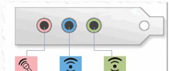
To begin with, it is worth making out which contacts in the plugs and sockets are for what, since in the mini and micro versions there is 1 pin more than in the connectors of the universal serial bus. So, the first pin is standardly marked with red insulation inside the wire, designed to supply voltage. The second and third pins, marked with white and green insulation, are for data transmission. The fourth black pin is zero or ground, paired with the first supply wire. In mini and micro USB, such functions are assigned to the fifth, last pin, and the fourth is a marking or identifier. It is designed to feed connection information to the device and is not connected anywhere in the data cables.

The simplest option
First of all, we will consider the option of connecting two specific devices, for example, a tablet computer and a camera. Since both of them have 5-pin sockets, be it micro or mini USB, you just need to carefully solder the corresponding wires together. 2 unnecessary data cables with matching plugs will do. You need to cut them and strip the wires from insulation, and then connect them according to color differentiation, that is, black with black, yellow with yellow, and so on. Each connection must be isolated from others with hot glue or at least electrical tape. When such a cable is connected to the devices, a dialog menu will appear on the screens, where you will need to select which of the devices will be the main one in this mini-network. You can forcefully designate the main and secondary devices in the cable itself. To do this, in the plug of the main device, you need to connect the 4th and 5th contacts, and in the other plug, simply do not connect the 4th contact to any one. Thus, the device will automatically identify itself as the master in the connection, since the marker contact will indicate the presence of a connection, while on the second device it will be "empty".
For a variety of devices
Consider the option of how to make a universal OTG cable with your own hands. In addition to a micro or mini USB plug, depending on the device, we need a USB connector. You can take it from old motherboards, cut it off from a USB extension cable, or disassemble a USB splitter (the so-called YUSB hub). The latter option is preferable, since it will allow you to connect several peripherals to the main device at once, like to a computer. The connection sequence is the same as above, the main device is forcedly indicated on the device plug in the same way, connecting the 4th and 5th pins. The figures clearly show the connection diagram of the pins in the connectors and plugs.

Connected to power
Some devices are characterized by increased power consumption, which leads to a quick discharge of the battery of the main gadget, be it a smartphone or tablet. In this case, the do-it-yourself OTG cable can be improved by adding a power cable with a USB plug for the power adapter. To do this, you can use the remnants of the data cable from which the micro or mini USB plug was previously cut off. The connection is made on two current-carrying contacts, black and red, ignoring the data wires. It should be remembered that over long distances, the resistance of the wire reinforced with solder joints will reduce the voltage and amperage, so using long cable lengths will most likely not allow you to achieve a stable connection between devices. Use approximately 20-30 cm of cable for each plug and connector to avoid breaks and interruptions in the connection.

Finally, I would like to mention how to assemble an OTG cable with your own hands without a soldering iron. The assembly principle is the same as described above, however, the wire connections are made in slightly different ways. Here are two of them:
Solder paste contains powdered solder and flux and does not require a soldering iron. This paste is applied to the parts to be joined and heated with a conventional lighter.
There are compounds without the use of high temperatures at all. The so-called adhesive tape locks are connectors for low-current systems with a special contact that cuts into the wires using a clamping device, pliers for example.
Whatever you plan to do with your own hands, remember that cutting the cables is not a warranty case and such cables cannot be replaced.
Almost any manipulator is connected to a computer using a special USB cable, thereby turning into an information input device. This allows you to create an entire ecosystem of various devices, but what if you need to trivially connect a keyboard to a tablet or smartphone?
For this, there are otg cables, which are in fact simply cleverly named adapters between micro-usb and usb. Allowing you to connect mice to the same smartphones and use them freely with the help of additional software and drivers, without restrictions. Such a cable for connecting external manipulators costs from a couple of dollars to a dozen, depending on the manufacturer, the quality and number of devices connected at a time. And the main question of our man in the street: how to make such a device yourself, so as not to waste money? Fortunately, for this, an old charger and an unnecessary connector, as well as pliers and electrical tape, are enough.
In fact, such a device does not have any complex microcircuits or adapters, all controller configuration occurs due to the internal software of the tablet or phone, therefore it is just a cable with input and output, which can be made in 10 minutes. And yet, how to make an otg cable with your own hands if you only have an old charger from a smartphone? Why do you need to connect external manipulators to mobile devices at all, and how to deal with differences in current strength of devices? And what do you need to know about OTG before using it?

Application methods
Before picking up a soldering iron, it is worth understanding why you need such a cable at all? After all, there are a lot of keyboards for the same tablet, specially created and designed for ease of use, not to mention gamepads and mice. Is this really a common adapter for those who cannot afford such a "zoo" of information input devices? In fact, this is a much more versatile device, because micro-usb is used in the same powerbank, and the phone or tablet itself with a sufficiently powerful battery becomes a separate device for recharging. So, you find yourself in a situation where the laptop is almost discharged, but the phone has 100 percent, here otg support will come in handy.
Yes, a 2-4 thousand mAh battery will not last long. But if we are talking about urgently responding to a letter or sending a project to the authorities, the time is already ticking by seconds. In addition, the opposite situation is also possible, and with the help of such adapters, you can always give some of the charge to a friend with a discharged smartphone. But before starting to celebrate cutting off the nearest old charger, make sure you have a soldering iron and a tin. In fact, the same OTG can be called a usb-c - micro-usb cable, which is simply necessary for the owners of new technology from Apple.

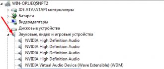
How to know if your device supports OTG cable
And now you have a pinout and a heated soldering iron in front of you, but it remains to check the last point, but is your device capable of supporting such connections at all that allow you to transfer the battery charge? Or connect third-party manipulators to it? It depends purely on the version of the android and partly on the modules sewn into the accessory, but to simplify your life, there are many testing programs that allow you to determine in a matter of minutes whether the phone is suitable for these purposes. As mentioned, if this is not the case, try updating the firmware and downloading the driver for the required accessory and you will be happy.

What tools will be needed
Those who did not miss the labor lessons at school already roughly represent the necessary tools for creating a cable. We only need to cut off the input and output of different charges and connect to each other using soldering, and then electrical tape, so take:
- Nippers or pliers, and be very careful here. Any extra spikes impair the communication speed between devices, increasing the resistance and decreasing the current, respectively.
- A knife or all the same pliers to strip the insulation, besides, you should not remove it completely, as some craftsmen do, a small piece of bare wire is enough, so you will reduce the chance of breaking the chain.
- Soldering iron. It doesn't matter if you have a Soviet device in your hands or a modern soldering iron with automatic shutdown when touching living matter. Remember the safety rules, keep it right. With some dexterity, you can also use a wood burning device. But it will take a little longer and leave traces of oxidation on it.
There are several tricks that will allow you to do without a soldering iron, which every Soviet child knows about. It is enough to use any filament or a sufficiently thick copper wire, and heat it up separately, while isolating it from direct contact with the skin. But if you have never even held a soldering iron in your hands, it is better not to risk doing it yourself without the help of a specialist.
Remember that the appliance cools down for a few minutes after use and try to prevent rosin and tin from getting on the table, especially if it is made of flammable materials. Try not to burn yourself, you can buy special protective gloves for this.
Soldering
First, a homemade cable should be cut according to the prepared scheme. Measure the required length and do not try to make it as long as possible, this can lead to inconvenience in use. Then strip the wire from the insulation, do not remove too much, this way you will increase the stability of the connection and reduce the chance of "fractures" in the solder. And you should not use a large amount of tin. The neater and more inconspicuous the connection, the greater the strength of the adapter and the charge transfer rate, and when the current strength is measured in 1 A, there is no need for excess resistance.
Having soldered and making sure that the metal has frozen, rewind the bare wire with electrical tape, again - a hundred layers will in no way affect the strength of the structure, so excessive fanaticism should be avoided here.

Check
Having installed all the necessary software and drivers on the phone, try the adapter, if it does not work, check the current with an ammeter. Is there a current? Then the problem is already directly in the smartphone, try testing your homemade product on another accessory or on a different firmware version!
Video instruction
Not all old tablets support the function of connecting a USB flash drive or a modem, but I will tell you how to outwit them and connect a USB flash drive, modem and even a hard drive to them.
Today I want to present to your attention an OTG adapter.
First, I want to tell you what OTG is? This is a way to connect to your tablet or phone that supports OTG function, printer, USB stick and even hard drive. This connection is also called USB-host.
You can also connect a keyboard or mouse to your gadget, if the gadget supports this function.
And so, to create this miracle cable, we need:
Old USB extension cable
Micro USB connector (you can get it from a regular USB cable for your device)
Soldering iron and soldering accessories
And so, let's go, in order for us to make such a cable, we will need to connect the 4th pin to the 5th pin of the micro USB connector
We need to get to the fourth contact and connect it with a jumper to the GND wire as shown in the picture

After we connect the 4th and 5th contacts with a jumper, our gadget will act as an active device and will understand that another passive device is going to be connected to it. Until we put the jumper on, the gadget will continue to act as a passive device and will not see your flash drives.
But that's not all, to connect a hard drive to a phone or tablet, this adapter will not be enough for us. To connect devices that have a consumption of more than 100mA, namely 100mA can be supplied by the port of your device, we need to connect an additional power supply to our OTG cable, which should be sufficient for your hard drive to work.
Here is a diagram of such an adapter

Now it's time to start collecting
We take an old USB extension cable and cut it not too far from the 2.0 connector, since the current is only 100mA to avoid large losses. Cut off approximately in the same place as shown in the photo

After we strip our wire


I connected 4 and 5 contacts with a drop of solder.
Well, here's all our cable assembly

It remains only to check the operability, we take the tablet, insert the "adapter" and insert the USB flash drive into it, everything works as the blinking LED on the flash drive tells us and the tablet identifying the USB flash drive.
The story of how difficult it was to connect a 4g modem, flash drives and a mouse to the tablet, and even not let it run out of power. Disassembly, tests of springs, Orico cables, a good thing, I recommend, not clause 18. All under the cut)
Hello! Today we are reviewing the mcroUSB-OTG hub with additional power. The review on it has already been on Muska, but very short, I will try to supplement it. It all started when I gave my parents a Prestigio Visconte Quad tablet (8 "", Intel Atom Z3735G, 1GB RAM, 16GB ROM, Windows 8.1 \\ 10). What was needed was a windows tablet so that the owners were as comfortable as possible to use, as on their laptop in general. I bought the tablet from a friend's hands, so the bundle was far from original: some kind of frivolous charging 1A and a microUSB cable was the first one that came to hand. As a result, during active use (wi-fi, online video, bluetooth mouse), the tablet was discharged while charging. Moreover, the modem connected via the 4g otg cable did not start, it appeared in the system, then fell off again at the stage of installing firewood. Thanks to the community at w3bsit3-dns.com I found out that the modem stupidly lacks the current strength. And the whole problem of survival with one microUSB is devoted. And I started making cables with additional power supply according to w3bsit3-dns.com schemes.
Scheme using scotch locks

Hub option

Everything worked, the modem started up, but using such cables was inconvenient, and the design itself did not last long. It was decided to kill all birds with one stone to purchase the factory version and the choice fell on the Acasis H-027. I immediately liked its austere design and modest, but original Acasis markings, which look like if it was written by Asus, I would not have doubted at all. I chose the cheapest lot at that time and received it 37 days later. There was no instruction in the kit (although some do). All packaging is a bubble wrap and a bag.


The device can operate in three modes:
1. Only charging
2.otg + charging
3. Only otg
A switch is provided to switch between them
 On my tablet, these modes worked like this:
 1.otg + charging
2.otg + charging
3. Only otg
The body of the device consists of two halves, fastened by the thorn-groove method. When disassembled, the thorns suffer and heroically fall off. Everything inside is clean and tidy.


The hub is controlled by the fe 1.1s microcircuit, very cheap, it can be found in many usb 2.0 hubs with ali, from very solid models to copies that literally fall apart in the hands. You can often find it in inexpensive Chinese tablets.

The indicator light signals that the power is connected. Implemented not very sensibly - just a hole in the case.

Otg-mode works flawlessly, I did not measure the speed of copying from drives, everything is normal there. Otg + charge mode with Orico colorful 0.5m cable
with three flash drives

with screw and flash drives

With a 4g modem, everything is also correct. Basically, for powering the tablet and the hub, I use a Robiton charger and an Orico microUSB cable 2m long.

In the maximum possible version: memory + 2 meters of cable + hub with a screw, modem and mouse, the tablet is slowly but charging, otg works i.e. the hub fulfills its purpose. Nevertheless, let's take measurements.
without a hub with a load of 1A

with hub and load 1A
I talked about choosing a tablet, and in particular about such a necessary function for me as the ability to connect various USB devices to it, such as: flash drives, a card reader (and accordingly memory cards of different formats), etc.
So, having bought a MoveO tablet! TPC-7HG I suddenly encountered a problem completely unexpected for me. The thing is that this tablet has only a mini-USB connector. In itself, this was not a surprise or a problem for me - on the contrary, it is easier to find a standard mini-USB cable to replace, for example, a failed charging cable on occasion. An unpleasant surprise for me was that in my town nowhere - ANYWHERE! - mini-USB OTG cable was not sold! It didn't come with the kit either. Going to all possible and impossible stores, I came to the conclusion that, perhaps, it would be easier and faster to make such a cable with your own hands.
ATTENTION!!! EVERYTHING YOU DO - YOU DO AT YOUR OWN RISK !!!
And now a little theory. You cannot simply take and solder together a mini-USB plug with a piece of wire from one cable and the so-called USB-female plug from another cable. No, that is, of course, you can solder something, but just connect to the tablet and make it work with this cable not a single device will work. Here's the thing.
The standard mini-USB cable has a five-pin plug:
001.
Contacts in it are numbered as follows:
002.
But a standard USB cable only has 4 wires. Where did the fifth wire go? Yes, nowhere. It simply does not solder to the end switches of the connector!
The purpose and color marking of wires in a regular USB cable are as follows:
1 - Red VBUS (+ 5V) +5 Volts DC voltage relative to GND. The maximum current is 500 mA.
2 - White D- (-Data)
3 - Green D + (+ Data)
4 - Black GND - common wire, "ground", "minus", 0 Volts
The main difference between the USB OTG cable is the plug. In a mini-USB OTG cable (however, as well as in a micro-USB OTG cable), pins 4 and 5 are closed together. In a regular (not OTG) data cable, a wire is not soldered to the 4th pin of the plug. This plug is called USB-BM mini (micro). If you solder pins 4 and 5 together, then such a plug will be called USB-AM mini (micro). It is by the presence of a jumper between 4 and 5 pins in the USB-AM micro plug that the tablet determines that a peripheral device is going to be connected to it. If this jumper is not present, then it will act as a passive device itself and will not react to any kind of USB devices connected to it.
So, we got acquainted with the theory - let's get down to practice.
We take a regular mini-USB cable, carefully open its connector with a clerical knife. As a result, we get this set of young technicians:
003.
Next, we need to connect the 4th and 5th pins of the plug. This can be done, for example, by carefully peeling off the sealing plastic from the back of the connector. But here two unpleasant surprises await. Firstly, it turns out to be not so easy to do, without damaging anything, because the contact group is poured into conscience - you dig out the hell. The second "surprise" is the short contact of the 4th contact (forgive my pun!), Which makes it extremely inconvenient to solder something to it:
004.
Honestly ruining the first cable, I take on the second one, but I am doing it a little differently. Having opened and disassembled the mini-USB connector, from the back of the contact pad, with the same clerical knife, I neatly scrape off the plastic in the area of \u200b\u200bthe 4th and 5th contacts right down to the contacts themselves:
005.
Now we take a soldering iron and put a neat jumper between these two contacts with tin.
006.
The only thing you need to watch out for here is to keep the contact pad as flat as possible, and both from this side - since in this case our connector may simply not fit back into its metal case, and from the opposite (that is, actually from the side of the contacts) - since the unevenness there can lead to bending of the contact group of the tablet socket, and this is already fraught. Having made a jumper, you need to take care to avoid short-circuiting the freshly soldered contacts with the connector body. To do this, I used such an indispensable tool as Poxipol.
007.
Please note that only TRANSPARENT Poxipol has electrical insulation. The metal Poxipol has quite conductive characteristics and, of course, cannot be used in this case.
After the Poxipol has hardened, the excess can be cleaned off with a knife, and the USB connector reassembled:
008.
In principle, it would be nice to pour Poxipol over it from above, but I recommend doing this after the cable has been tested for operability.
And we cut off the USB-mother connector from it with a piece of wire:
010.
Now we only need to connect the two received cables (one with the mini-USB connector, the other with the USB-female connector) between each other.
First, we "dress" one of the wires with heat shrinkage:
011.
Take the soldering iron again:
012.
And carefully solder (from the word "solder" and not "solder"!) The wires in the cables.
013.
To insulate the wires from each other, I used the same Poxipol. And when he froze, he put everything on top with heat shrinkage:
014.
As a result, we got such a cable.