The USB cable pinout refers to the description of the internals of the Universal Serial Bus. This device is used to transfer data and charge batteries of any electronic devices: mobile phones, players, laptops, tablet computers, tape recorders and other gadgets.
Carrying out high-quality pinouts requires knowledge and the ability to read diagrams, orientation in the types and types of connections, you need to know the classification of wires, their colors and purpose. Long and uninterrupted operation of the cable is ensured by the correct connection of the wires of 2 connectors USB And mini USB.
Types of USB connectors, main differences and features
The Universal Serial Bus comes in 3 versions - USB 1.1, USB 2.0 and USB 3.0. The first two specifications are fully compatible with each other, the 3.0 tire has a partial overlap.
USB 1.1 is the first version of the device used for data transfer. The specification is used only for compatibility, since 2 operating modes for data transfer ( Low-speed and Full-speed) have a low rate of information exchange. Low-speed mode with a data transfer rate of 10-1500 Kbps is used for joysticks, mice, keyboards. Full-speed is used in audio and video devices.
USB 2.0 added a third mode of operation - High-speed for connecting storage devices and video devices of a higher organization. The connector is marked with HI-SPEED on the logo. The information exchange rate in this mode is 480 Mbps, which is equal to the copy speed of 48 Mbps.
In practice, due to the design and implementation of the protocol, the throughput of the second version turned out to be less than the declared one and is 30-35 MB / s. The cables and connectors of the Universal Bus Specifications 1.1 and Generation 2 have an identical configuration.
The third-generation universal bus supports 5 Gb/s, which is equal to 500 MB/s copy speed. It is available in blue, making it easy to identify which plugs and sockets belong to the upgraded model. Bus 3.0 current increased from 500mA to 900mA. This feature allows you not to use separate power supplies for peripheral devices, but to use the 3.0 bus to power them.
Specifications 2.0 and 3.0 are partially compatible.
Classification and pinout
With descriptions and designations in the tables of USB connectors, it is assumed by default that the view is shown from the outside, working side. If the view from the mounting side is supplied, then this is specified in the description. In the scheme, insulating elements of the connector are marked in light gray, metal parts are marked in dark gray, cavities are indicated in white.

Despite the fact that the serial bus is called universal, it is represented by 2 types. They perform different functions and provide compatibility with devices with improved performance.
Type A includes active, powered devices ( computer, host), to type B - passive, connected equipment ( printer, scanner). All sockets and plugs of Gen 2 and Rev 3.0 Type A busbars are designed to work together. The 3rd generation bus jack type B connector is larger than the version 2.0 type B plug, so a device with a universal bus 2.0 type B connector is connected using only a USB 2.0 cable. Connecting external equipment with 3.0 type B connectors is done with both types of cables.
Classic type B connectors are not suitable for connecting small electronic equipment. Connection of tablets, digital equipment, mobile phones is carried out using miniature connectors Mini-USB and their improved modification Micro-USB. These connectors have reduced plug and socket dimensions.
The latest modification of the USB connectors is type C. This design has the same connectors at both ends of the cable, it is characterized by faster data transfer and more power.
Pinout USB 2.0 connector types A and B
Classic connectors contain 4 types of contacts, in mini- and microformats - 5 contacts. Wire colors in USB 2.0 cable:
- +5V ( red VBUS), voltage 5 V, maximum current 0.5 A, designed for power supply;
- D-( white) Data-;
- D+ ( green) Data+;
- GND ( black), voltage 0 V, is used for grounding.

For mini format: mini-USB and micro-USB:
- Red VBUS (+), voltage 5 V, current 0.5 A.
- White (-), D-.
- Green (+), D+.
- ID - for type A they are closed to GND, to support the OTG function, and for type B they are not used.
- Black GND, voltage 0V, used for ground.
Most cables have a Shield wire, it has no insulation, it is used as a shield. It is not marked and is not assigned a number. The universal bus has 2 types of connector. They have the designation M ( male) and F ( female). Connector M ( dad) is called a plug, it is inserted, connector F ( Mother) is called a nest, they are inserted into it.
USB 3.0 pinout types A and B
Bus version 3.0 has a 10 or 9 wire connection. 9 pins is used if the Shield wire is missing. The arrangement of contacts is made in such a way that devices of earlier modifications can be connected.
USB 3.0 pinout:
- A - plug;
- B - nest;
- 1, 2, 3, 4 - contacts that match the pinout in specification 2.0 have the same color scheme;
- 5, 6 contacts for data transfer via the SUPER_SPEED protocol are designated SS_TX- and SS_TX+, respectively;
- 7 – grounding GND;
- 8, 9 – pads of wires for receiving data via the SUPER_SPEED protocol, pin designations: SS_RX- and SS_RX+.

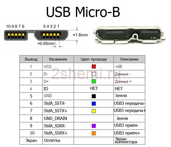
Micro USB pinout
The Micro-USB cable has 5 pad connectors. A separate mounting wire is supplied to them in the insulation of the desired color. In order for the plug to fit accurately and tightly into the socket, the upper shielding part has a special chamfer. The micro USB contacts are numbered 1 to 5 and read from right to left.
The pinouts of the micro- and mini-USB connectors are identical, presented in the table:
The shield wire is not soldered to any pin.

Mini-USB Pinout
Mini-A and Mini-B connectors appeared on the market in 2000, using the USB 2.0 standard. To date, little used due to the emergence of more advanced modifications. They were replaced by micro connectors and USB type C models. The mini connectors use 4 shielded wires and an ID function. 2 wires are used for power: supply +5 V and ground GND. 2 wires for receiving and sending differential data signals, designated D+ and D-pin. Data+ and Data- signals are transmitted via . D+ and D- always work together, they are not separate simplex connections.
USB connectors use 2 types of cables:
- shielded, 28 AWG stranded, rated at 28 AWG or 20 AWG without twist;
- unshielded, 28 AWG without twist, 28 AWG or 20 AWG without twist.

The length of the cable depends on the power:
- 28 - 0.81 m;
- 26 - 1.31 m;
- 24 - 2.08 m;
- 22 - 3.33 m;
- 20 - 5 m.
Many manufacturers of digital equipment develop and complete their products with connectors of a different configuration. This can make it difficult to charge your mobile phone or other devices.
Universal USB buses are one of the most popular computer interfaces. They debuted back in 1997, and just three years later, a new modification (2.0) appeared, 40 times faster than the original. However, despite such progress, manufacturers have realized that the speed is still not enough to use external hard drives and other high-speed devices. And today a new USB interface (type 3.0) has appeared. The new standard exceeded the speed of the previous version (2.0) by 10 times. This article is devoted to such a question as desoldering the USB connector. This information may be useful to radio amateurs who independently manufacture any USB adapters or devices that are powered via a USB bus. In addition, consider what the pinout of a micro-USB and mini-USB USB connector is.
Description
Many radio amateurs have encountered a problem when an incorrectly connected USB bus port led to the burning of flash drives and peripherals. To avoid such situations, it is necessary that the USB connector is wired correctly, in accordance with accepted standards. The USB 2.0 connector is a flat connector with four pins, it is marked AF (BF) - “mother” and AM (BM) - “father”. Micro-USBs have the same markings, only with the micro prefix, and mini-type devices, respectively, with the mini prefix. The last two types differ from the 2.0 standard in that these connectors already use 5 pins. And finally, the most recent type is USB 3.0. Outwardly, it looks like type 2.0, however, this connector uses as many as 9 pins.
Pinout of USB connectors
The pinout of the USB 2.0 connector looks like this:
The first wire (red color), it is supplied with a DC supply voltage of +5 V;
The second contact (white color), it is used for (D-);
The third wire (green), it is also designed to transmit information (D +);
The fourth contact (black), it is supplied with zero supply voltage, it is also called a common wire.
As mentioned above, the micro and mini types are a five-pin USB connector. The pinout of such a connector is identical to type 2.0, except for the fourth and fifth pins. The fourth pin (purple) is the ID. In type B connectors, it is not used, and in type A connectors it is closed to a common wire. The last, fifth output (black color) is zero supply voltage.

type 3.0
The first four contacts are completely identical to the 2.0 standard, we will not dwell on them. The fifth pin (blue) is used to transfer information with a minus sign USB3 (StdA_SSTX). The sixth output is the same, but with a plus sign (yellow). Seventh - additional grounding. The eighth pin (purple) is for receiving USB3 data (StdA_SSRX) with a minus sign. And finally, the last ninth is the same as the seventh, but with a plus sign.
How is the USB charging port wired?
Any charger uses only two wires from the USB connector: + 5V and a common contact. Therefore, if you need to solder a USB 2.0 or 3.0 type connector to “charging”, then you should use the first and fourth pins. If you are using mini or micro types, then you need to solder on the first and fifth pins. The most important thing when applying the supply voltage is to observe the polarity of the device.
The correct pinout of the plug and socket of the Micro-USB connector for connecting power and charging a mobile phone or tablet.
Pinout diagram
Pin assignment of the micro-USB connector - socket and plug
The USB (Universal Serial Bus) connector is a universal serial bus, the most common wired method for connecting external devices to a computer. This connector allows you to organize data exchange between a computer and a video camera, card reader, MP3 player, external hard drive, smartphone.
Charging the battery via Micro-USB
In addition, a 5 volt supply voltage is supplied through it to charge the battery of wearable gadgets. Since almost all modern lithium batteries have an operating voltage of 3.7 V, the 5 V coming through the Micro-USB are excellent for replenishing energy. True, not directly to the battery, but through the charger converter.

I am glad that the pinout of the connector is the same for all smartphone manufacturers - Samsung, LG, Huaway and others. Thus, a 220 V charger adapter from one phone is most often suitable for charging another without changing the pinout.
- The main advantage of the Micro-USB connector over other types is the ability to connect Plug & Play devices without the need to restart the computer or manually install drivers. Devices can be connected while the computer is running and disconnected without having to press any buttons.
The difference between Micro-USB A and B
Please note: The micro connector contains 5 pins. In connectors of type "B" the fourth contact is not used. In connectors of type "A" the fourth contact is closed with GND (minus). And for GND - the fifth contact.

The USB connector is a Universal Serial Bus. Today, this connector in various form factors is present on almost any electronic gadget or device. However, due to long-term operation, a negative situation may arise - the connector either breaks off or is soldered off (taking into account the presence of high temperatures).
For more information on how to replace the connector, see the article below. It should be remembered that all the above methodology, if used by you, is only at your own peril and risk! As a rule, when a non-professional tries to fix complex electronics on his own, everything ends extremely badly.
Many professionals in the event of the above situation are advised to purchase a new connector. For the price, it's worth every penny. Sold in any computer shop.
In order not to confuse the connector with anything, it is better to go shopping with the old connector (which fell off). Buy exactly the same. The following is a set of tools that you will definitely need to perform a connector replacement:
- flux for soldering;
- soldering iron with a thin tip;
- rosin;
- solder.
The standard UBS connector has several pins. It is extremely important that these pins fall into the vias that are designed specifically for them. But before placing the connector on the board, it is recommended to strip the contacts.
This is done using an ordinary rubber eraser, which is used to remove a simple pencil from paper. This will eliminate the possibility of poor contact after soldering.

It should be noted right away that it is recommended to solder the leads in such a way that excess solder does not stick out. After all, it conducts electricity, which means it can short to ground if the board is incorrectly installed in a laptop (or any other device).
In order for a non-professional to solder correctly, it is recommended to use flux or rosin. This will keep the solder from sticking to the tip of the soldering iron.
As a result, soldering will be accurate and durable.
It is extremely important not to overheat the board itself during soldering. After all, it has paths. If overheated, they can rise, which will disrupt the entire operation of the device.
The video will demonstrate how you can replace the USB connector on your laptop yourself:
- in order to use the USB inputs installed in front of the system case, they must first be connected to the PC motherboard. This publication will discuss how to properly organize and perform such a connection.
Modern motherboards now mostly come with four, six, or eight USB connectors. But they are installed directly into the system board, as a rule, there are only two or four connectors on the back side. In this regard, in most cases we have a couple of USB ports left on the motherboard. These connectors are usually made in nine or ten pin connectors.
USB pinout on motherboard
One of the most significant problems is that global manufacturers do not use a common standard for motherboards in their manufacture. Therefore, the assignment of each pin in connectors from different board manufacturers may differ in functionality from motherboards from another brand. For this reason, personal connectors are used for any USB connector wire on the front panel of the system unit.
Unsoldering the USB 2.0 connector on the motherboard
On each connector housing there are special designations like this: + 5V, D+, D- and GND (housing), but the values \u200b\u200bare indicated slightly differently, although the essence is the same.
| No. pin | Wire color | Name | Description |
|---|---|---|---|
| 1 | Red | 5V,VCC,Power | Nutrition |
| 2 | Red | 5V,VCC,Power | Nutrition |
| 3 | White | D- | Data- |
| 4 | White | D- | Data- |
| 5 | Green | D+ | Data+ |
| 6 | Green | D+ | Data+ |
| 7 | Black | GND | Earth |
| 8 | Black | GND | Earth |
| 9 | — | Key(No pin) | Key |
| 10 | Grey | GND | Earth |
All you have to do is install each of the wires (+5V, D+, D- and GND) in the correct places as shown above.
Unsoldering the USB 3.0 connector on the motherboard
| No. pin | Name | Description | No. pin | Name | Description |
|---|---|---|---|---|---|
| 1 | IntA_P2_D+ | Data+ | 2 | ID | Identifier |
| 3 | IntA_P2_D- | Data- | 4 | IntA_P1_D+ | Data+ |
| 5 | GND | Earth | 6 | IntA_P1_D- | Data- |
| 7 | IntA_P2_SSTX+ | Data+ | 8 | GND | Earth |
| 9 | IntA_P2_SSTX- | Data- | 10 | IntA_P1_SSTX+ | Data+ |
| 11 | GND | Earth | 12 | IntA_P1_SSTX- | Data- |
| 13 | IntA_P2_SSRX+ | Data+ | 14 | GND | Earth |
| 15 | IntA_P2_SSRX- | Data- | 16 | IntA_P1_SSRX+ | Data+ |
| 17 | Vbus | Nutrition | 18 | IntA_P1_SSRX- | Data- |
| 19 | Key(No pin) | Key | 20 | Vbus | Nutrition |
How to connect the front panel to the motherboard