USB (Universal Serial Bus - "Universal Serial Bus") is a serial data interface for medium-speed and low-speed peripheral devices. A 4-wire cable is used for connection, with two wires used for receiving and transmitting data, and 2 wires for powering the peripheral device. With built-in uSB power lines allows you to connect peripherals without their own power supply.
USB basics
USB cable consists of 4 copper conductors - 2 power conductors and 2 data conductors in twisted pair, and a grounded braid (shield).USB cables have physically different tips "to the device" and "to the host". It is possible to implement a USB device without a cable, with a tip “to the host” built into the case. One-piece integration of the cable into the device is also possible(e.g. USB keyboard, Webcam, USB mouse)although the standard prohibits this for full and high speed devices.
USB bus strictly oriented, that is, it has the concept of a "master device" (a host, also known as a USB controller, is usually built into the south bridge microcircuit on the motherboard) and "peripheral devices".
Devices can be powered by +5 V from the bus, but they can also require an external power supply. The standby mode is also supported for devices and splitters on a command from the bus, with the main power being removed while maintaining the standby power and turned on by a command from the bus.
USB supportsHot plugging and unplugging of devices... This is possible due to the increase in the length of the conductor of the grounding contact in relation to the signal. When connected uSB connector the first to close grounding contacts, the case potentials of the two devices become equal and further connection of the signal conductors does not lead to overvoltages, even if the devices are powered from different phases of the three-phase power network.
At the logical level, a USB device supports data transmission and reception transactions. Each package of each transaction contains a number endpoint on the device. When a device is connected, drivers in the OS kernel read a list of endpoints from the device and create control data structures to communicate with each endpoint on the device. The collection of endpoint and data structures in the OS kernel is called pipe.
Endpoints, and hence channels, belong to one of 4 classes:
- in-line (bulk),
- manager (control),
- isochronous (isoch),
- interrupt
Low-speed devices such as mice cannot have isochronous and streaming channels.
Control channel is intended for exchange with the device in short “question-answer” packets. Any device has control channel 0, which allows OS software to read brief information about the device, including the manufacturer and model codes used to select the driver, and a list of other endpoints.
Interrupt channel allows you to deliver short packets in both directions, without receiving a response / confirmation, but with a guarantee of delivery time - the packet will be delivered no later than N milliseconds. For example, it is used in input devices (keyboards, mice, or joysticks).
Isochronous channel allows you to deliver packages without a delivery guarantee and without replies / confirmations, but with a guaranteed delivery speed of N packets per bus period (1 KHz for low and full speed, 8 KHz for high speed). Used to transmit audio and video information.
Streaming channel provides a guarantee of delivery of each packet, supports automatic suspension of data transmission due to the device's unwillingness (buffer overflow or underflow), but does not guarantee the speed and delay of delivery. Used, for example, in printers and scanners.
Bus time divided into periods, at the beginning of the period the controller transmits a packet "start of period" to the entire bus. Further, during the period, interrupt packets are transmitted, then isochronous in the required amount, in the remaining time in the period, control packets are transmitted, and last of all streaming ones.
Active side of the bus there is always a controller, the transfer of a data packet from a device to a controller is implemented as a short question of the controller and a long response of the device containing data. The packet movement schedule for each bus period is created by a joint effort of the controller hardware and driver software, for this many controllers use DMA Direct Memory Access (Direct Memory Access) - the mode of data exchange between devices or between the device and the main memory, without the participation of the Central Processor (CPU). As a result, the transfer rate increases as no data is sent to and from the CPU.
The packet size for an endpoint is a constant hardwired into the device's endpoint table and cannot be changed. It is selected by the device developer from among those supported by the USB standard.
USB Specifications
Features, advantages and disadvantages of USB:
- High speed of exchange (full-speed signaling bit rate) - 12 Mb / s;
- Maximum cable length for high speed exchange - 5 m;
- Low exchange rate (low-speed signaling bit rate) - 1.5 Mb / s;
- Maximum cable length for low baud rate - 3 m;
- Maximum connected devices (including multipliers) - 127;
- Connection of devices with different exchange rates is possible;
- There is no need to install additional elements such as terminators;
- Supply voltage for peripheral devices - 5 V;
- The maximum current consumption per device is 500 mA.
USB signals are transmitted over two wires of a shielded 4-wire cable.
Pinout of USB 1.0 and USB 2.0 connectors
| Type A | Type B | ||
| Fork (on cable) |
Power socket (on the computer) |
Fork (on cable) |
Power socket (on the peripheral device) |
 |
|||
USB 1.0 and USB 2.0 Pin Names and Functions
Disadvantages of USB 2.0
Although the maximum uSB 2.0 baud rate is 480 Mbit / s (60 MB / s), in real life it is unrealistic to achieve such speeds (~ 33.5 MB / s in practice). This is due to the large delays of the USB bus between the request for data transfer and the actual start of the transfer. For example, the FireWire bus, although it has a lower peak bandwidth of 400 Mbit / s, which is 80 Mbit / s (10 MB / s) less than that of USB 2.0, in reality allows you to provide more bandwidth for exchanging data with hard drives and other storage devices. In this regard, a variety of mobile storage devices have long been "running into" the insufficient practical bandwidth of USB 2.0.
The USB interface began to be widely used about 20 years ago, to be precise, in the spring of 1997. It was then that the universal serial bus was implemented in hardware on many motherboards in personal computers. At the moment, this type of connection of peripherals to a PC is a standard, versions have been released that have significantly increased the speed of data exchange, new types of connectors have appeared. Let's try to understand the specifications, pinouts and other features of USB.
What are the benefits of Universal Serial Bus?
The introduction of this connection method made it possible:
- Quickly connect a variety of peripheral devices to your PC, from the keyboard to external disk drives.
- Fully use the "Plug & Play" technology, which simplified the connection and configuration of peripherals.
- Rejection of a number of outdated interfaces, which had a positive effect on the functionality of computing systems.
- The bus allows not only data transmission, but also power supply of connected devices, with a load current limitation of 0.5 and 0.9 A for the old and new generation. This made it possible to use USB to charge phones, as well as connect various gadgets (mini fans, lights, etc.).
- It became possible to manufacture mobile controllers, for example, an RJ-45 USB network card, electronic keys for entering and exiting the system
Types of USB connectors - the main differences and features
There are three specifications (versions) of this type of connection, partially compatible with each other:
- The very first version, which was widely used - v 1. It is an improved modification of the previous version (1.0), which practically did not leave the prototype phase due to serious errors in the data transfer protocol. This specification has the following characteristics:
- Dual-mode data transfer at high and low speeds (12.0 and 1.50 Mbps, respectively).
- The ability to connect more than a hundred different devices (including hubs).
- The maximum cord length is 3.0 and 5.0 m for high and low exchange rates, respectively.
- The rated bus voltage is 5.0 V, the permissible load current of the connected equipment is 0.5 A.
Today this standard is practically not used due to its low bandwidth.
- The currently dominant second specification .. This standard is fully compatible with the previous modification. A distinctive feature is the presence of a high-speed data exchange protocol (up to 480.0 Mbit per second).
Due to full hardware compatibility with the junior version, peripheral devices of this standard can be connected to the previous modification. However, this will reduce the throughput by up to 35-40 times, and in some cases even more.
Since there is full compatibility between these versions, their cables and connectors are identical.
Note that, despite the bandwidth indicated in the specification, the real data exchange rate in the second generation is slightly lower (about 30-35 MB per second). This is due to the peculiarity of the protocol implementation, which leads to delays between data packets. Since the read speed of modern drives is four times higher than the throughput of the second modification, that is, it did not meet the current requirements.
- The 3rd generation universal bus was specially designed to solve the problem of insufficient bandwidth. According to the specification, this modification is capable of exchanging information at a speed of 5.0 Gbps, which is almost three times higher than the read speed of modern drives. It is common practice to mark plugs and sockets of the latest modification in blue to facilitate identification of accessories to this specification.

Another feature of the third generation is an increase in the rated current to 0.9 A, which allows powering a number of devices and eliminating the need for separate power supplies for them.
As for compatibility with the previous version, it has been partially implemented; details of this will be described below.
Classification and pinout
Connectors are usually classified by type, there are only two of them:

Note that such convectors are only compatible between earlier modifications.

In addition, there are extension cords for the ports of this interface. At one end of them there is a type A plug, and at the second there is a socket for it, that is, in fact, a "mother" - "father" connection. Such cords can be very useful, for example, to connect a USB flash drive without getting under the table to the system unit.

Now let's look at how the contacts are wired for each of the above types.
Pinout of usb 2.0 connector (types A and B)
Since the plugs and sockets of earlier versions 1.1 and 2.0 do not physically differ from each other, we will show the wiring of the latter.
 Figure 6. Wiring of the plug and socket of the type A connector
 Designation:
- A - nest.
- B - plug.
- 1 - power supply +5.0 V.
- 2 and 3 signal wires.
- 4 - mass.
In the figure, the coloring of the contacts is given by the colors of the wire, and corresponds to the accepted specification.
Now let's look at the wiring of the classic socket B.

Designation:
- A is a plug that connects to a socket on peripheral devices.
- B is a socket on a peripheral device.
- 1 - power contact (+5 V).
- 2 and 3 - signal contacts.
- 4 - contact of the wire "mass".
The colors of the contacts correspond to the accepted coloring of the wires in the cord.
USB 3.0 pinout (types A and B)
In the third generation, peripheral devices are connected via 10 (9, if there is no braided shield) wires, respectively, the number of contacts is also increased. But they are positioned in such a way that it was possible to connect devices of earlier generations. That is, the +5.0 V, GND, D + and D- pins are located the same as in the previous version. The wiring of the type A socket is shown in the figure below.
 Figure 8. Pinout of the Type A connector in USB 3.0
 Designation:
- A - plug.
- B - nest.
- 1, 2, 3, 4 - connectors fully correspond to the pinout of the plug for version 2.0 (see B in Fig. 6), the colors of the wires also match.
- 5 (SS_TX-) and 6 (SS_TX +) connectors for SUPER_SPEED data transmission wires.
- 7 - ground (GND) for signal wires.
- 8 (SS_RX-) and 9 (SS_RX +) connectors for receiving data using the SUPER_SPEED protocol.
The colors in the illustration correspond to those generally accepted for this standard.
As mentioned above, an earlier plug can be inserted into the socket of this port, respectively, the throughput will decrease. As for the third-generation universal bus plug, it is not possible to fit it into the early release sockets.
Now let's look at the pin wiring for a type B socket. Unlike the previous type, such a socket is incompatible with any plug of the earlier versions.

Legend:
A and B are plug and socket, respectively.
Digital signatures for contacts correspond to the description in Figure 8.
The color is as close as possible to the color marking of the wires in the cord.
Micro usb connector pinout
To begin with, we present the wiring for this specification.

As you can see from the picture, this is a 5 pin connection, both in the plug (A) and in the socket (B) there are four pins involved. Their purpose and digital and color designation correspond to the accepted standard, which was given above.
Description of the micro USB connector for version 3.0.
For this connection, a 10 pin connector is used. In fact, it consists of two parts, 5 pin each, and one of them fully corresponds to the previous version of the interface. This implementation is somewhat confusing, especially considering the incompatibility of these types. Probably, the developers planned to make it possible to work with connectors of early modifications, but subsequently abandoned this idea or have not yet implemented it.

The figure shows the pinout of the plug (A) and the appearance of the socket (B) of the micro YUSB.
Pins 1 to 5 fully correspond to the second generation micro-connector, the purpose of other pins is as follows:
- 6 and 7 - data transmission using high-speed protocol (SS_TX- and SS_TX +, respectively).
- 8 - mass for high-speed information channels.
- 9 and 10 - data reception via high-speed protocol (SS_RX- and SS_RX +, respectively).
Mini USB pinout
This connection option is used only in earlier versions of the interface, in the third generation this type is not used.

As you can see, the wiring of the plug and socket is almost identical to the micro YUSB, respectively, the color scheme of the wires and the contact numbers are also the same. Actually, the differences are only in shape and size.
In this article, we have given only standard types of connections, many manufacturers of digital equipment practice the implementation of their standards, there you can find connectors for 7 pin, 8 pin, etc. This introduces certain difficulties, especially when it comes to finding a charger for a mobile phone. It should also be noted that manufacturers of such "exclusive" products are in no hurry to tell how the USB pinout is made in such contactors. But, as a rule, this information is easy to find on thematic forums.
The section is updated daily. Always the latest versions of the best free programs for everyday use in the Necessary programs section. There is almost everything you need for your daily work. Start gradually abandoning pirated versions in favor of more convenient and functional free counterparts. If you still do not use our chat, we highly recommend that you get acquainted with it. There you will find many new friends. It is also the fastest and most efficient way to contact project administrators. The section Antivirus updates continues to work - always up-to-date free updates for Dr Web and NOD. Didn't have time to read something? The full content of the creeping line can be found at this link.
Universal Serial Bus or USB for short
Universal Serial Bus or USB for short is actively used in modern digital computer technology. Currently, USB 1.1 and USB 2.0 are used. The USB 2.0 version supports forward and backward compatibility with USB 1.1. In other words, USB 2.0 devices work well with computers equipped with USB 1.1 and vice versa. All USB 1.1 and USB 2.0 cables and connectors are the same.
USB
USB (short for the English term Universal Serial Bus - "universal serial bus", pronounced "u-es-bi") is a serial data interface for low-speed and medium-speed peripherals in digital computing.
Universal Serial Bus (USB) - "universal serial bus" has its own special designation, that is, its own special graphic symbol.
USB symbol
The USB symbol is represented by four geometric shapes: a large circle, a small circle, a triangle, and a square, located at the ends of the tree block diagram. The USB symbol can be applied to equipment cases, connectors and devices.
USB 2.0 differs from USB 1.1 by the introduction of Hi-speed mode. USB 2.0 High Speed \u200b\u200bhas its own logo.

USB 2.0 High Speed \u200b\u200blogo printed on Card Reader

Fig. 1. An example of a USB cable. USB symbols on connectors are clearly visible
To connect peripheral devices to the USB bus, a special four-core cable is used, while two cores (twisted pair) in differential connection are used for data exchange, and the other two are used to power the peripheral device, see Fig. 2.

Fig. 2. USB cable marked with basic parameters
USB allows you to connect peripheral devices without their own power source (the maximum current consumed by the device via the USB bus power lines should not exceed 500 mA) see Fig. 3.

Fig. 3. USB has its own power lines, this allows you to connect peripheral
devices without their own source e.g. external hard drive
One USB bus controller allows you to connect up to 127 devices in a star topology, including hubs. A single USB bus can contain up to 127 devices and up to 5 levels of hub cascading, not counting the root.
Due to its versatility, USB is gradually replacing ports such as COM and LPT. Fortunately, manufacturers of printers and scanners provide for the operation of their devices with USB and provide the appropriate connectors. In addition, new non-traditional USB devices such as compact MP3 players are emerging. The USB connection allows not only copying music files to such players, but also charges the built-in battery, which ensures the player's autonomous operation.
USB cable
The USB cable is four-core braided, it consists of 4 copper conductors - 2 power conductors and 2 conductors for data transmission in the form of a twisted pair, plus a grounded braid (shield), see Fig. 4.

Fig. 4. USB cable. The various connectors at the ends of the cable are clearly visible.
This is due to the fact that USB cables are oriented
USB cables are oriented, for this USB cables are supplied with different connectors for connecting "to the device" and "to the host". It is possible to implement a USB device without a cable, with a tip “to the host” built into the case. An example of such a device is a flash memory stick or USB modem. It is also possible to permanently embed the cable into the device, an example is a computer mouse, see Fig. 5. (the standard prohibits this for full and high speed devices, but manufacturers violate it). There are (although prohibited by the standard) and passive USB extenders that have connectors "from the host" and "to the host".

Fig. 5. Non-detachable embedding of the USB cable into the device.
For example, a computer mouse has a built-in USB cable.
USB 1.1 and USB 2.0. Connectors, cables and wiring
Wiring diagram for USB connectors (cable and device)

Wiring diagram for USB connectors (cable and device)
USB signals are transmitted over two wires (twisted pair) of a shielded four-wire cable.
VBUS - voltage +5 Volt of the power circuit, GND - contact for connecting the "body" of the power circuit. The maximum current drawn by the device through the USB bus power lines must not exceed 500 mA. Data is transferred via pins D- and D + of the USB connector. Differential data transfer is basic for USB.
The USB 2.0 cable is shielded for higher data transfer rates. It is also four-core, but braided, consists of 4 copper conductors in color insulation. Two power conductors and 2 twisted pair data conductors. The wires are placed in a grounded braid (shield).
USB cable connectors
For the USB cable, special USB connectors are used. The USB cable is directional, therefore, for correct connection, USB connectors have different configurations. There are two types of USB connectors: Type A (see Fig. 7. and Fig. 8.) and Type B (see Fig. 9., Fig. 10 and Fig. 11).

Fig. 7. Common USB cable connector Type A
In accordance with the 1.0 specification USB Type A connectors are used for connection "to the host" ie. installed on the side of the controller or USB hub.

Fig. 8. "Proprietary" USB cable connector Type A (with the name of the manufacturer)
In accordance with the 1.0 specification USB Type B connectors are used for connecting "to a device" ie. for connecting peripheral devices.

Fig. 9. A normal USB cable connector Type B. This connector is suitable, for example,
to connect the printer

Fig. 10. Normal USB mini cable Type B

Fig. 11. Micro USB cable connector Type B.
In the figure below the USB symbol, the designation Type B is clearly visible
Figure 12. and Fig. 13. shows USB cables. These USB cables are equipped with a regular USB Type A cable connector and a USB mini Type B cable connector.

Fig. 12. USB cables are equipped with a regular USB cable connector
B

Fig.13. USB cables are equipped with a regular USB cable connector
Type A (pictured on the left) and USB mini cable
Type B (pictured to the right). Type B is designated as b

Fig. 14. USB cable equipped with a miniature connector called micro USB
USB supports hot (power on) plugging and unplugging. This is achieved by the increased length of the grounding contact of the connector in relation to the signal contacts, see Fig. 15. When the USB connector is connected, the grounding contacts are closed first, the potentials of the two devices' cases are equalized and further connection of the signal conductors does not lead to overvoltages, even if the devices are powered from different phases of the three-phase power network.

Fig. 15. Grounding contact length
The length of the grounding contact (pin 4 GND in the figure at the top) of the connector is increased in relation to the signal (pin 3 D + in the figure below) contacts. The top contact is longer than the bottom one. This allows you to connect and disconnect devices without turning off the power (so-called "hot" plugging and unplugging)
Mating parts of USB connectors are located on peripheral devices connected via USB, see Fig. 16. and Fig. 17.

Fig. 16. Connector for connecting the USB cable connector. The USB symbol is clearly visible

Fig. 17. Connector for USB mini cable connector Type B

Fig. 18. Comparison of sizes of USB connectors.
A regular USB cable connector Type A (in the figure on the left), a USB mini cable connector Type B (in the figure in the center) and a USB micro connector for a Type B cable (in the figure on the right). Type B is designated as B
Content:
In our age of computer technology, smartphones and gadgets, it is difficult to find a person who does not know what USB connectors are. Also, almost everyone understands words such as mini- and micro-USB connectors. After all, we use such things almost daily, which is natural. Similar connectors are found on the charger and on all computer peripherals.
But what if the wiring has moved away at the base, and there is no way to even understand what color and on what contact was soldered? This is where knowledge should be applied, and what, now let's try to figure it out.
The pinout of such a plug, or, in other words, the pinout of the USB wire, in its essence, does not carry anything super complicated. Once you figure out the sequence and colors, anyone who can hold a soldering iron can handle this job.
But first you need to understand what constitutes a USB plug.
What is a USB connector?
At its core, it is a connector with many possibilities, ranging from USB power to the transfer of complex information data. A similar cable replaced the previously used options for connecting to a computer (PS / 2 ports, etc.). It is used today for all devices connected to a personal computer, be it a mouse, flash drive, printer, camera or modem, joystick or keyboard - USB cables have become truly universal.
There are three types of such connectors:
- 1.1 - its purpose - outdated already peripheral devices with the ability to transfer information only one and a half megabits per second. Of course, after a slight modification by the manufacturer, the transmission speed rose to 12 Mbit / s, but with higher-speed options it still could not stand the competition. Of course, when Apple already had a connector supporting 400 Mbps. Now there are such types too, but there are very few of them, since faster USB cables, mini USB, and in general, the speed of USB in a person's life has a special place long ago. Everyone is in a hurry somewhere, in a hurry to live, there are people who practically do not sleep, and therefore, the faster the information is downloaded, the more preferable the connector is, right?
- 2.0. At the end of the last century, the second generation of such connectors was released. Here the manufacturer has already tried - the transmission speed has grown to almost 500 Mbit / s. And it was intended mainly for sophisticated gadgets, such as a digital video camera.
- 3.0 is really high technology. The limiting data transfer rate of 5 Gbps ensured the demand for this USB connector, which practically nullified the first and second versions. In the third series, the number of wires has been increased to nine versus four. However, the connector itself has not been modified, and therefore you can still use the types of the first and second series with it.
Pinout designations
Considering the pinout scheme, you must understand all the designations that are present on it. Usually indicated:

- Connector type - it can be active (A) and passive (B). Passive is the connection of a printer, scanner, etc. In general, a connector that only works for receiving information. Through active it is possible to receive and transmit data.
- The shape of the connector is female for female (F) and male for male (M).
- Connector sizes are regular, mini and micro.
For example USB AM, that is, an active USB plug.
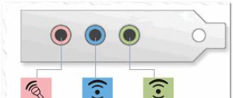
The wires should be arranged by color as follows (from left to right):
- Red wire - positive, constant voltage 5V. with a maximum current of 500 milliamperes.
- White wire - data-
- Green wire - data +
- Black wire - this wire is common, "ground", "minus". There is no tension on it.
But the mini and micro connectors include 5 wires with the following arrangement:
- Red, white and green wires are located similarly to the first option.
- ID - this wire in the B connectors is free. In "A" it must be shorted to a black wire.

Sometimes a separate wire without insulation may be present in the connector - this is the so-called "mass", which is soldered to the case.
According to the presented diagrams, the outer side is visible here. In order to solder the plug on your own, you need to take a mirror image of the picture, and as you probably realized, microUSB pinout is not at all more complicated than that of conventional USB connectors.
By the way, if the damaged parts of the cable are supposed to be used only for charging mobile phones, it will be more convenient, after looking at the colors of the wires, to solder only black and red. This connector is quite enough for a phone, it will charge it. What to do with the rest of the wires? You don't need to do anything with them.
This article provides general information about the USB standard as well as pinoutUSB connectorin all kinds of colors (USB, mini-USB, micro-USB, USB-3.0).
USB (Universal Serial Bus) connector Is a universal serial bus, a modern way of connecting external devices to a personal computer. Replaces previously used connection methods (serial and parallel port, PS / 2, Gameport, etc.) for common types of peripherals - printers, mice, keyboards, joysticks, cameras, modems, etc. Also, this connector allows you to organize the exchange of data between a computer and a video camera, card reader, MP3 - player, external hard drive.
The advantage of the USB connector over other connectors is the ability to connect Plug & Play devices without having to restart the computer or manually install drivers. Plug & Play devices can be plugged in while the computer is running and can be up and running within seconds.
When a new device is connected, first the hub (cable hub) receives a high level over the data line, which indicates that new equipment has appeared. Then the following steps follow:
- The Hub informs the Host Computer that a new device has been connected.
- The host computer asks the hub to which port the device was connected to.
- After receiving a response, the computer issues a command to activate this port and resets the bus.
- The hub generates a reset signal (RESET) with a duration of 10 msec. The output current of the device is 100 mA. The device is now ready for use and has a default address.
USB is a collaboration between Compaq, NEC, Hewlett-Packard, Philips, Intel, Lucent and Microsoft. The USB standard was intended to replace the widely used RS-232 serial port. USB is generally easier for the user and has more bandwidth than the RS-232 serial port. The first USB specification was developed in 1995 as a low-cost universal interface for connecting external devices that did not require a lot of data bandwidth.

Three USB versions
USB 1.1
The USB 1.1 version was designed to serve slow peripherals (Low-Speed) with a data transfer rate of 1.5 Mbps and fast devices (Full-Speed) with a data transfer rate of 12 Mbps. USB 1.1, however, failed to compete with a high-speed interface, for example. FireWire (IEEE 1394) from Apple with data transfer rates up to 400 Mbps.
USB 2.0
In 1999, they began to think about the second generation of USB, which would be applicable to more complex devices (for example, digital video cameras). This new version, designated USB 2.0, was released in 2000 and provided a maximum speed of up to 480 Mbps in Hi-Speed \u200b\u200bmode and retained backward compatibility with USB 1.1 (data transfer type: Full-Speed, Low-Speed).
USB 3.0
The third version (also referred to as Super-speed USB) was designed in November 2008, but, probably due to the financial crisis, its mass distribution was delayed until 2010. USB 3.0 is more than 10 times faster than USB 2.0 (up to 5 Gbps). The new development has 9 wires instead of the original 4 (the data bus already consists of 4 wires), however, this standard still supports USB 2.0 and provides lower power consumption. This allows you to use any combination of USB 2.0 and USB 3.0 devices and ports.
The USB connector has 4 pins. A twisted pair (two wires twisted together) is connected to the DATA + and DATA- pins, and ordinary wires are connected to the VCC (+5 V) and GND pins. Then the entire cable (all 4 wires) is shielded with aluminum foil.
Below is the pinout (wiring) of all types of USB connectors.
Types and pinout of USB connectors
Wiring the USB cable by color:

- +5 volts
- -Data
- + Data
- General
USB connector pinout - type A:


USB connector pinout - type B:


Wiring the cable according to the colors of the connectors: mini (mini) and micro (micro) USB:

- +5 volts
- -Data
- + Data
- Not used / General
- General
Pinout of the mini-USB connector - type A: