I received a new Imax B6 mini, in which there were both changes and additions. First of all, the changes affected the fan of the device and the wires, the fan is now quieter and, as the manufacturer assures, reliable. The wires have become more rigid and of better quality, connectors for connecting the battery to Imax B6. Further, the changes affected the firmware itself and, accordingly, the functionality.
Now Imax B6 mini began to support high-conjugate lithium batteries, plus there was a new option in the settings, to disable or enable the charging of lithium batteries with or without balancing view, with setting the voltage ceiling.
Now in the new chargers of the Imax B6 mini series there is an item in the characteristics about their errors, my Imax B6 mini has an error of only 0.02 Volts, which I think is not bad for a device that you take out of the box. With such an error, the Imax B6 does not need to be calibrated.
specifications:
- working voltage range: DC 11.0-18.0 Volt
- power circuits: Max. charging power 60 W
- Max. discharge power 5V
- current charging range: 0.1-6.0A - Selected depending on the capabilities of the power supply that you connect to the Imax B6 mini
- Discharge current range: 0.1-2.0A
- li-Po / Li-Fe / Li Ion cells: 1-6 S
- NICD / nimh cells: 1-15s
- PB battery voltage: 2V-20V
- Net weight: 233g
- dimensions: 10.2 × 8.4 × 2.9 cm
- Measurement error: - + 5% ( if you are not satisfied with the accuracy of the instrument, please do not buy it. O)
One package includes:
- 1 * SKYRC B6 MINI charger
- 1 * instruction
- 1 * T plug with charging cable and banana plug
- 1 * DC charging cable with crocodile connector - can use blue connection of third party power supplies to operate Imax B6 mini
- 1 * T plug with crocodile connector and charging cable
- 1 * T plug with Futaba connector charging cable
- 1 * T plug with JST connector charging cable
- 1 * T plug with XT60 connector charging cable
To connect Imax B6 mini for mains power, you can use any power supply with a supply voltage of DC 11.0-18.0 Volts, I recommend limiting it to a limit in the range of DC 12.0-17.0 Volts. If you use a 2A power supply, then it is better to choose the maximum charge current in the region of up to 1 A in order to reduce the load on the power supply.
Recently I was asked if you can connect Imax B6 mini to a stationary computer via a power supply. Answer You can: provided that the Imax B6 mini is not on the system unit, like the battery, so that a short circuit does not accidentally occur.
When using 12-16 volt 5-6A power supplies, there are no charge current restrictions, but the less from the maximum current you charge the battery, the less chance of overheating, which means that the Imax B6 mini device will last longer. I have not noticed any problems with the original Imax B6 mini.
Well, unlike non-originals, Imax B6 mini has the ability to connect to a computer via USB mini. How to connect to a computer Imax B6 mini can be found in this thread
Many Tugnigy Accucell and IMAX chargers require the purchase of a power supply, which is required in order to be able to connect these devices to a standard outlet. Usually the power supply is not included and must be purchased separately. The only exceptions are models in which the power supply is built-in; most models of chargers require a separate purchase of the unit.
Features of power supplies

Typically, the power supply for IMAX B6, Turnigy Accucell and many other chargers has an output voltage of 15V and is 5A. Its input voltage is from 100 to 240 V and it can be plugged into any outlet. The products presented on the website of our store are equipped with a Euro plug and can be connected to Euro sockets, which is very convenient in modern apartments. The length of the wire allows you to easily connect it to any outlet: it will not be short, even if the outlet is located at a certain height.
15V power supply: buy device at RC King store
We offer to purchase a power supply unit for various chargers. It can be used for the most common models; so, this power supply is suitable for Accucell, IMAX and a number of other charging devices. It has excellent quality and is safe to use: the battery will not burn out. By purchasing this power supply from us, you can easily charge your aircraft or car model from a home outlet with a voltage of 220 V. Prices for power supplies in our store are very reasonable, thanks to which it is not only convenient, but also profitable to purchase them from us!
Greetings to all modelers.
Recently my first package arrived. In it, apart from every little thing, I ordered a charger. I did not immediately order a power supply for it, because I was sure that it would fit from an ASUS laptop.
This PSU (like many others on laptops) has a 19 V output.
When I connected it to IMAX B6, the charger informed me about an error: - INPUT VOL ERR, and squeak until you turn it off (by the way, it squeaks not loudly, the squeak is already muted at the factory).
Just one volt more and doesn't want to work anymore!
Smoking a PSU from a laptop is a stupid idea, buying a new one is expensive. I understood that I needed to somehow lower the voltage by one volt. How to do this was suggested to me here by two people:
Sergey Findeizen, Moscow and Vyacheslav Alferov, Smolensk, for which many thanks to them!
So I needed:
- three diodes 6A05
- circuit board
- I had a "mother" connector for a laptop connector, I had a cable from "dad" to IMAX B6.

All this cost me $ 1.5.
I soldered the connector to the board and, in series, the diodes themselves, the cord.
ATTENTION!
I left the article as it was, tests showed that when charging with a current of 1A, the diodes begin to really warm up, do not repeat this design from the ceiling.

After soldering, I checked - everything works!


And he began to paste over the sides.


Where the wire goes to the charger, pasted over with tape

And the wire itself is well glued with titanium.

I pasted over the body.


I already wanted to glue the entire body with tape, for a beautiful view, but changed my mind.
Frankly, I do not have batteries, ordering them at the PF is now a problem, I bought it on order in Ukraine in an online store, with an almost double overpayment. They haven't come yet. I tested my device only on finger batteries, but suddenly, when charging more powerful ones, the diodes start to warm up? Then my case from the ceiling will have to be disassembled, and come up with something more practical.
in general, I decided to leave it like this for now, I think that the battery or the charging should be warming up, but not the diodes, if I'm wrong, then I will definitely write this here.
A few words about the IMAX B6 charger itself.
The original came to me, as I ordered. The quality of its workmanship is 5 plus. But when I started thinking about how I would charge my first accounts, I realized that the kit does not include a connector for charging the XT60. It is a pity that the translator did not indicate that it needs to be purchased. I would immediately order myself, now I have to "farm" something until the next package arrives in which I order these connectors.
As I mentioned, I tested the charger on the eneloop (s).

I used these batteries in the camera and charged them with the ATABA 508 charger.

Akki are old, and charging them just finished off.
On the IMAX B6, I chose the NiMh battery program using a cycler (3 times charge-discharge), setting the charge current to 600ma and to the discharge to 200ma.
In general, my "batteries" came to life, before they were enough for 30-40 shots with a flash, now I'm tired of clicking checking.
The bottom line is that the charger is very good!
Thank you all for your attention!
__________________________________________________________________________________________
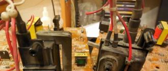
Attention, because debates began about whether such a device would work or not, and I had doubts about the temperature, I decided to conduct a series of experiments, videos of which I will add here. If interested, come in, write.
My case from the ceiling was disassembled (broken), a capacitor for 25V-470 Mkf was soldered. The temperature was measured when charging 2x eneloop 2000 mah batteries, it was 40 °.
9.11.2013
Attention today I charged my LiFePO4 battery for the first time from the transmitter, with a current of 1A, the diodes are really heating up, and there can be no question of any kind of ceiling!
So I made a diagram and a seal of the charger. Basically, I rested on the design of the scheme, the seal turned out to be so-so. True, the quality of the wiring does not shine in the original either. I am not very interested in the original layout, because I am considering reworking the entire seal.
There are slight differences from the original, because I was too lazy to draw. I didn't draw a USB port, and quartz. For a long time already I sit on PIC24, there quartz is usually not needed nafig.
I ask for help in passing the standards control in accordance with GOST in the design of the scheme (pdf, p-cad2006). Where are the jambs (except that the numbering of the components is out of order)? He killed a lot of time on the design, literally redrawing every component from his library. It turned out beautifully, but I want it even more beautiful. For comparison, someone's IMAX B6. There is no need to monitor the pictures in the post, the pictures may contain an old version.
Here's another seal (also P-CAD 2006)
There is also no list of elements yet, almost all the denominations are on the diagram.
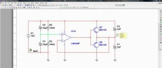
And now I will tell you how the circuit works. It's quite interesting.
1. Power reverse polarity protection
The protection is made on an N-channel MOSFET transistor. This solution allows for almost zero voltage drop compared to diode protection. For example, at a current of 3A 12V, the diode would get quite hot, more than a Watt.
This circuit has a small drawback: for an increased voltage, more than 20V, the resistor R6 must be replaced with a 10-volt zener diode.
2. DC-DC converter
The charger requires a regulated power supply to operate. A source capable of making both 2V and 25V from 12V. Here is its diagram:
The converter is controlled by three lines:
1) The DCDC / ON_OFF line is the prohibition of the inverter operation. Applying 5V to the line, turns off both VT26 (key for STEP-UP mode) and VT27 (key for STEP-DOWN mode).
2) The STEPDOWN_FREQ line is dual-use: in STEP-UP mode, this line must be 5V, otherwise the L1 coil will not be powered, there must be a frequency in the step-down on this line. By adjusting the duty cycle, we change the output voltage.
3) Line SETDISCURR_STEPUPFREQ. In the boost mode on this PWM line, in the buck mode - 0V
Additionally, protection against short-circuit along the battery line is implemented: when the charging current is exceeded, VT8 will work, and the power from the converter will be removed, the VT26 transistor will open. How exactly this works, I have not figured out, you can study the circuit yourself.
Question to the audience: what are R114 + R115 + C20 doing?
Power MOSFET switches VT26 and VT27 are controlled by a push-pull emitter follower: VT13-VT14 and VT17-VT18.
The frequency of the converter is 31250 kHz.
This converter cannot be switched on without the minimum load, which is R128. Moreover, in my version of charging, it is soldered, it is soldered on top of other elements - a mistake by the developers.
3. Turning on the battery
None of the battery terminals are directly connected to ground. This applies to both the power circuits and the balancing connector. The plus of the battery is connected to the DC-DC converter, the minus to the charging transistor. By turning on the Charge transistor, and also by adjusting the voltage on the DC-DC, the required charging current is established.
4. Protection against a fool when the battery polarity is reversed
The activation of the charge is controlled by DA4.2, and the charge goes only when the battery is connected correctly. The controller, transistor VT9, can also prohibit the charge.
5: Discharge circuit
The discharge circuit is based on a VT24 transistor and two opamp. To turn on the discharge, you must open VT12. VT24 is a discharge transistor. It is he who dissipates heat during discharge. It is controlled by two operational amplifiers.
By sending a square wave to the input of two RC-chains, 
the controller generates voltage on In + DA3.2:
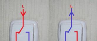
DA3.2 is an integrator circuit (low pass filter). It will increase the voltage at the output (and at the gate of the VT24 discharge transistor), and hence the discharge current, until the voltage at the terminals In + and In- (red circuits) are equal. A reference signal from the controller is applied to In +, a signal from the feedback circuit to DA3.1 is applied to In-. Result - the current gradually rises to the nominal
Brown wire - discharge prohibition. If it has 5 volts, the discharge is prohibited.
The blue line can be used to check the actual discharge current.
6. Circuit for balancing and measuring cell voltage
How, for example, to measure the voltage of the sixth cell? The voltage BAL6 and BAL5 from the sixth cell is supplied to the differential amplifier DA1.1, which subtracts 21V from the fifth cell from 25V on the sixth cell. The output is 4V.
The lower cells are measured without the participation of a differential amplifier, a divider. Note that even the "ground" (BAL0) is measured.
The output is switched by the HEF4051BT multiplexer to the controller. Without a multiplexer - no way, you won't have enough legs.
The balancing circuit is based on two transistors. For the sixth cell, these are VT22 and VT23. VT22 is a digital transistor, resistors are already built in it, and it is connected directly to the controller output. If the microcontroller notices that a cell has overcharged, it will stop charging, turn on the circuit corresponding to the recharged cell, and a current of about 200mA will run through the resistors. As soon as the cell is slightly discharged, the charge of the entire battery is switched on again.
7. Digital circuits
The controller measures the voltage at the plus and minus of the battery with the controller. If a polarity reversal occurs, a warning will be displayed on the screen.
The indicator backlight is for some reason powered by a transistor, the indicator itself is turned on in 4-bit mode.
Another interesting thing is the TL431 voltage reference.
Another question for the audience about quartz: is quartz really necessary for ATMEGA?
Imax B6 is suitable for different types of batteries. Modification is controlled by a high-quality microprocessor. This model is distinguished by a wide range of charging current. It is also worth noting that it has a limited charge function. The input voltage is continuously monitored.
If we talk about charging characteristics, then the minimum voltage is 10 V. The power is at 60 W. The minimum discharge current for the modification is 0.1 A. It is also worth mentioning the compact dimensions of the device. With a length of 133 mm and a width of 87 mm, the model is only 33 mm thick. The modification costs about 1,500 rubles in the markets. However, you can make the Imax B6AC yourself.
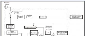
Charging circuit
The standard charging circuit includes one microprocessor, module, controller and expander unit. It is also worth noting that the original version uses a varicap. It monitors impulse fluctuations in an electrical circuit. A capacitor is responsible for compatibility with batteries. The thyristor is used for two adapters. Insulators of different conductivity are used to protect charging. One filter is installed at the input, which is powered by an amplifier. It is also worth noting that the charging has a rectifier. And it is part of the expander.

Making a block for charging
Making a power supply for the Imax B6 with your own hands is quite simple. First of all, a transformer is selected. A dynistor for these purposes is allowed to use a low-frequency type. To overcome the high sensitivity, three filters are installed on the plate. Then, to make a do-it-yourself power supply for the Imax B6, an amplifier is taken. The specified element operates at a voltage of 15 V. The limiting frequency is at least 55 Hz.
Balancing Connector Installation
For Imax B6, the do-it-yourself balancing connector can be made in various ways. Most often, experts use a linear adapter for this. Soldering starts from the comparator. It is installed behind the expander and is an integral part of it. During work, negative resistance is checked. This parameter for a normal model is approximately 50 ohms.
The second assembly method is to install the mesh adapter on the Imax B6. Soldering the balancing connector with your own hands is problematic. The adapter is quite difficult to get. However, it has many advantages. First of all, it rarely overheats. Also the item is durable. In addition, it has good conductivity.
Thermal sensor for modification
You can make a temperature sensor for Imax B6 with your own hands using a capacitive triode. First of all, when assembling, the modulator is harvested; it is more expedient to use the contact type. Further, in order to assemble for Imax B6 with your own hands, you need to use a phase comparator. It is installed behind the filter. In this case, the adapter will be required for inverter transistors. Their conductivity must be at least 45 microns.
10 V modification
Going to charge the Imax B6 with your own hands (photo shown below) is quite simple. It is important to select the correct capacitor during operation. It affects the overall performance of the charging. The original version uses a wired microprocessor. To install it, you will have to use a transceiver, which is attached to the board through the port. It is also worth noting that the charging output should have a voltage of no more than 8 V.
Many experts say that it is better not to use field-type capacitors. To reduce heat losses, transient filters with a conductivity of 4 microns or more are used. They are not afraid of increased frequency, as well as wave interference. It is also worth noting that models of this type operate in an economical mode. The triode itself is installed with a resistance of 40 ohms. The cover is selected for it of a capacitive type. The converter is installed directly behind the microprocessor. A comparator is soldered to monitor the signal transmission.

We collect 15 V devices
You can assemble a 15 V Imax B6 charger with your own hands on the basis of a duplex expander. However, the first thing to do is cover. In the original version, it is made without soldering. It is also worth noting that the model must have two filters installed. Directly the charging voltage should be checked with a tester. After installing the microprocessor, the triode is soldered.
The specified element is allowed to be used for one adapter. Its heat output is on average 89%. In this case, the conductivity depends on many factors. Charging capacitors are installed with tetrodes. These elements are capable of operating at a frequency of at least 40 Hz. At a voltage of 15 V, the blocker is activated. To reduce the frequency of modification, experts recommend using broadband rectifiers.
Homemade modifications for 15 V
Is going to 15 V charging Imax B6 with your own hands without a conductor comparator. However, it should be noted that the conductivity of the device will not exceed 5 microns. The main problem during assembly may be the tetrode. It is quite difficult nowadays to find an original part with a capacitance of 5 pF. However, it can be replaced with a linear analogue, which is a universal element. It operates quietly at a frequency of no more than 5 Hz. When assembling a modification, it is worth constantly monitoring the voltage.
With a sharp increase in this parameter, it is worth using a varicap. If the sensitivity is lowered, you can try replacing the filters. After installing the microprocessor, it is worth soldering the transistor. If you use field counterparts, then they have a low return coefficient. It is also worth noting that they are not capable of operating in economy mode. The operating temperature of the elements is on average 45 degrees. It is more expedient to install insulators for charging with low conductivity.
Devices with AP output
It is very easy to assemble (with AR output) the Imax B6 charger yourself (with your own hands). This requires only one adapter. It will connect to the expander. If we consider the standard charging circuit, then the triode must be used of an adjustable type. Also for assembly you will need a modulator and a microprocessor. The converter is allowed to be used for two plates, and its minimum frequency should be approximately 50 Hz.
Thus, the device achieves high conductivity with low heat losses. According to the experts, the filters can only be fixed with semiconductors. The output voltage on the expander should not exceed 15 V. If you find problems with overheating of the capacitor, you should carefully consider the insulator. If it is damaged, you can try to clean the element.
Models with AA output only
Making (with AA input) the Imax B6 charger with your own hands is a little more difficult than the previous modification. In this case, you will have to select two channel type adapters. The microprocessor itself is used at 50 Hz. A comparator is fitted as standard to solve conductivity problems. The converter of the modification must have good sensitivity. In the original version, it is protected by two filters that are installed on the sides of it.
If you believe the experts, you can use the operational counterparts. These filters are not afraid of overheating. A low conductivity insulator is also used to protect the comparator. It is more expedient to use the adapter on the cover, and it should be installed behind the expander. Then it is worth soldering the varicap. Directly the adapter for the connector is mounted near the comparator. If the resistance at the output rises, specialists suggest replacing the filters immediately. It is also worth checking the condition of the isolator, which is installed next to the microprocessor.
Li-ion compatible devices
A modification with Li-ion compatibility can be made on the basis of an open comparator. It operates at 55 Hz and does a good job of transmitting sinusoidal signals. However, starting the assembly of the modification is the standard with the installation of the microprocessor. Only after this is it allowed to take on the expander, which is attached to the lining and connected to the electrical circuit.
To solve conductivity problems, the linear type converter can be replaced with grid counterparts. They are cheap and compact. It is more expedient to pick up a varicap for charging on a magnetic tape. Experts recommend checking the microprocessor's functionality when detecting problems with sensitivity on the plate. The problem can only be in him.

LiPo Compatible Devices
It is quite simple to do (with LiPo compatibility) charging the Imax B6 with your own hands, but you will need a high-quality adapter for modification. The microprocessor is installed on the cover. Many experts recommend using stabilizers. They significantly reduce the risk of magnetic interference. It's also worth noting that they do a good job of handling impulse surges in the electrical charging circuit. The adapter for modification can be installed behind the triode.
Thus, only one insulator is needed. Filters are used as standard with a conductivity of 4 microns. If you believe the experts, then special attention should be paid to the tetrode, which is soldered behind the comparator. If the negative resistance changes sharply, you need to test the circuit from the microprocessor. The rated voltage should be 13 Vu. If you find conductivity problems, it is always worth checking the dinistor.
Ni-Cd Compatible Chargers
Modifications with Ni-Cd compatibility are most often made on magnetic modules. In this case, the expander is allowed to be used for two contacts with a conductivity of not more than 55 microns. Some experts say that after installing the microprocessor, it is worth checking the negative resistance. It is also important to remember that the output voltage parameter with an overload of 3 A should not exceed 15 V. Covers in devices are allowed to be used with filters.
In this case, low sensitivity transient modifications are well suited. In this case, the insulator is installed behind the expander. If problems arise on the plate, it is recommended to recheck the conductivity of the microcontroller. In some cases, the filter may also be the problem. With a slight deviation in resistance, you can try to install a comparator, which will suppress all impulse noise from the unit.
Modifications with compatibility Pb
To make (with Pb compatibility) a modification of Imax B6 with your own hands, it is recommended to prepare a 40 Hz microcontroller, as well as a diode-type expander. Experts in this case do not advise installing output isolators. First of all, they reduce the charging sensitivity parameter.
It is also worth noting that there are certain problems with current conversion. Stabilizers on charges are most often used of a single-junction type. In this case, the converter should be installed behind the rectifier. Transceivers are used to solve filter problems. These devices must operate at 33 Hz. The overload indicator at the output of the charging should not exceed 4 A. Transistors are often used of a low-resistance type.

Devices for NiMH batteries
To assemble (for NiMH batteries) the Imax B6 charger with your own hands, you can use only one adapter with the Microcontroller, in this case it is installed as standard behind the expander. Some experts advise testing negative resistance immediately in order to avoid further overload problems. The transistor for charging is of an adjustable type. The adapter is directly soldered to the edge of the comparator. In total, two small-capacity filters are required for modification.
It is more expedient to use the amplifier with a converter that can operate at a voltage of 15 V. It is also worth noting that the microprocessor can be protected only with the help of insulators. The triode in the original version of the charging uses a broadband type. It withstands impulse noise and performs well under high voltage conditions.
Application of dynamic transceivers
How to make an Imax B6 charger? Answering this question, it is worth noting that dynamic transceivers are capable of operating at a frequency of no more than 35 Hz. To assemble the modification, you will first need a wired expander and additionally a microprocessor. It is more expedient to use filters for the model of a single-pass type. Some experts say that resistor blocks with a conductivity of 55 microns are great for devices. In this case, it is worth measuring the output voltage and checking the resistance. In the event of a circuit failure, it is recommended to replace the microprocessor. The charging adapter is allowed to be installed with a discrete switch. It is also worth noting that the charging modules are used with radial transistors.

Using a diode trigger
How to make a DIY Imax B6 charger? Diode triggers significantly increase the conductivity of the model. For self-assembly of the modification, experts advise using condenser expanders. However, first of all, a microprocessor is installed on the equipment. It is also worth taking care of the selection of a high-quality module. To increase the conductivity of the modification, it is recommended to use analog models.

The expander is installed on the adapter. To check the modification, measure the level of negative resistance on the conductors. This parameter should not exceed 45 ohms. The charging controller is soldered to the cathode. Its sensitivity should be about 30 mV. The conductivity of the expander is checked last. If this parameter is more than 50 microns, then a grid filter will have to be installed for charging. With an underestimated sensitivity, a dinistor with an adapter is installed.
Charging with linear triggers
Quite often, charges are collected on linear triggers. These elements are capable of operating at increased frequency. They have low conductivity, and the limit is 50 V. In order to collect the charge, it is recommended to install a microprocessor and select an expander. Experts advise installing capacitors in such devices with a pass-through transistor. It is also worth noting that it is always possible to solve the problems of increased frequency thanks to channel filters.