Introduction
Efficiency
Luminous efficiency, measured in lumens per watt (lm / W, lm / W), is a value used to determine the efficiency of converting energy (in our case, electrical) into light. Conventional incandescent bulbs operate in the range of 10-15 lm / Wt. A few years ago, the standard LED efficiency was around 30 lm / Wt. But by 2006, the efficiency of white LEDs had more than doubled: one of the leading manufacturers, Cree, was able to demonstrate 70 lm / W in prototypes, representing a 43 percent increase over the maximum light output of their commercial white LEDs. In December 2006, Nichia announced new white LEDs with an efficacy of 150 lm / W achieved. These samples demonstrated a luminous flux of 9.4 lumens with a color temperature of 4600 K at a current of 20 mA under laboratory conditions. The declared efficiency is approximately 11.5 times higher than that of incandescent lamps (13 lm / W), 1.7 times higher than that of modern fluorescent lamps (90 lm / W). Moreover, the high pressure sodium lamps (132 lumens / watt), which are the best efficient light source among traditional lamps, have been exceeded.
Advantages
Solid State Light (SSL) is still not well known, despite the variety of ways it is produced and implemented through LEDs. Most companies and designers are only familiar with traditional analog white lighting, with no real appreciation of the beneficial and useful alternatives provided by LED applications. In addition to the easily predictable benefits that can be obtained from solid-state LED lighting (energy savings, long service life, etc.), attention should be paid to the following specific features of LEDs as new sources of white light:
- low heat generation and low supply voltage (guarantees a high level of safety);
- the absence of a glass bulb (determines a very high mechanical strength and reliability);
- no heating or high starting voltages when turned on;
- inertialess on / off (reaction< 100 нс);
- no DC / AC converter required;
- absolute control (adjusting brightness and color in full dynamic range);
- the full spectrum of emitted light (or, if required, a specialized spectrum);
- built-in light distribution;
- compactness and ease of installation;
- absence of ultraviolet and other radiation harmful to health;
- no hazardous substances such as mercury are used.
How to get white light using LEDs?
Black is the absence of all colors. When light from all parts of the color spectrum overlaps (that is, all colors are present), the cumulative mixture appears white. This is the so-called polychromatic white light. The primary colors from which all shades can be obtained are red, green and blue (RGB). Secondary colors, also called complementary: lilac (a mixture of red and blue); blue (a mixture of green and blue); and yellow (a mixture of red and green). Any complementary color and opposite primary color also add up to white light (yellow and blue, cyan and red, lilac and green).
There are various ways to get white light from LEDs.
The first is color mixing using RGB technology. On one matrix, red, blue and green LEDs are densely placed, the radiation of which is mixed using an optical system, for example, a lens. The result is white light. Another, less common approach, mixes primary and secondary color LEDs to produce white light.
In the second method, a yellow (or green plus red) phosphor is applied to a blue LED, as a result, two or three radiations are mixed, forming white or close to white light.
The third method consists in the fact that three phosphors emitting blue, green and red light, respectively, are applied to the surface of the LED emitting in the ultraviolet range. This is similar to how a fluorescent lamp shines.
The fourth method for producing white light using LEDs is based on the use of a ZnSe semiconductor. The structure is a blue ZnSe LED "grown" on a ZnSe substrate. The active area of the conductor emits blue light, while the substrate emits yellow.
|
Crystal type |
Phosphor |
Radiation color and possible shades |
Areas of use |
||
|
Blue and Green |
White + R, G, B and any multicolor combinations |
LCD backlight, architecture, landscape, boards and displays |
|||
|
White + B, Y and various multicolor shades |
|||||
|
Blue green |
Red or red-orange |
White + B, R and various multicolor shades |
Automotive lighting, architecture, landscape |
||
|
Blue 470-450 nm |
Only white |
General lighting and lighting |
|||
|
UV |
White or various monochromatic colors depending on the phosphorus used |
General lighting and lighting |
|||
|
Blue yellow |
White + blue from epitaxial layer, yellow from substrate |
General lighting and lighting |
|||
Which is the best way?
Each of them has its own advantages and disadvantages. The color mixing technology, in principle, allows not only to obtain white, but also to move along the color chart when the current passed through different LEDs changes. This process can be controlled manually or by means of a special program. In the same way, it is possible to obtain different color temperatures. Therefore, RGB matrices are widely used in light-dynamic systems. In addition, the large number of LEDs in the matrix ensures high total luminous flux and high axial luminous intensity. But the light spot due to the aberrations of the optical system has an unequal color in the center and at the edges, and most importantly, due to uneven heat removal from the edges of the matrix and from its middle, the LEDs heat up differently, and, accordingly, their color changes differently in the process of aging - the total color temperature and color "float" during the operation. This unpleasant phenomenon is difficult and expensive to compensate for.

White phosphor-converted LEDs are significantly less expensive than RGB LEDs (per unit luminous flux) and produce good whites. And for them, in principle, it is not a problem to get to the point with coordinates (X = 0.33, Y = 0.33) on the CIE color chart. The disadvantages are as follows: firstly, they have less light output than RGB matrices due to the conversion of light in the phosphor layer; secondly, it is rather difficult to accurately control the uniformity of the phosphor deposition in the technological process (as a result, the color temperature is not controlled); and thirdly, the phosphor also ages, and faster than the LED itself.
ZnSe white LEDs offer a number of advantages. They operate at 2.7 V and are highly static-resistant. ZnSe LEDs emit light in a much wider range of color temperatures than GaN-based devices (3500-8500 K versus 6000-8500 K). This allows you to create appliances with a "warmer" glow, which is preferred by Americans and Europeans. There are also disadvantages: although ZnSe-based emitters have a high quantum yield, they are short-lived, have high electrical resistance, and have not yet found commercial use.
Application
Colour temperature
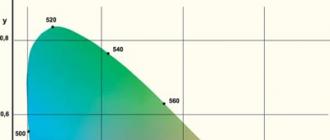
Consider the emission spectrum of a white LED with a phosphor as a source of polychromatic light. White LEDs offer a wide range of color choices from warm white incandescent to cool fluorescent white, depending on the application.

This chart shows the full range of white from its warmer 2800 K region to the cool bluish white region of 9000 K. Many shades of white are already defined by the various light sources used in our environment: office, cool bluish white fluorescent light; homemade, yellowish-white light from incandescent lamps; industrial, brilliant blue-white light from mercury lamps; yellow-white light from outdoor high pressure sodium lamps.
White LED
Powerful white LED
There are two types of white LEDs:
- Multichip LEDs, more often three-component (RGB-LEDs), which include three semiconductor emitters of red, green and blue light, combined in one package.
- Phosphor LEDs created on the basis of an ultraviolet or blue LED, which contain a layer of a special phosphor, which converts, as a result of photoluminescence, part of the LED radiation into light in a relatively wide spectral band with a maximum in the yellow region (the most common design). The radiation of the LED and phosphor, when mixed, give white light of various shades.
History of invention
The first semiconductor emitters of red color for industrial use were obtained by N. Holonyak in 1962. In the early 70s, yellow and green LEDs appeared. The light output at the beginning of low-efficiency devices reached the level of one lumen by 1990. In 1993, Suji Nakamura, an engineer at Nichia, Japan, created the first high-brightness blue LED. Almost immediately, RGB LED devices appeared, since blue, red and green colors made it possible to obtain any color, including white. White phosphor LEDs first appeared in 1996. Later, the technology developed rapidly and by 2005 the light output of LEDs reached 100 lm / W or more. LEDs with various shades of light appeared, the quality of light made it possible to compete with incandescent lamps and with already traditional fluorescent lamps. The use of LED lighting devices began in everyday life, in indoor and outdoor lighting.
RGB LEDs
White light can be created by mixing LEDs of different colors. The most common trichromatic construction is from red (R), green (G) and blue (B) sources, although there are bichromatic, tetrachromatic and more multicolored variants. A multi-color LED, unlike other RGB semiconductor emitters (lamps, lamps, clusters), has one complete body, most often similar to a single-color LED. The LED chips sit next to each other and share a common lens and reflector. Since semiconductor chips have finite size and their own radiation patterns, such LEDs most often have uneven angular color characteristics. In addition, it is often not enough to set the design current to obtain the correct color ratio, since the light output of each chip is not known in advance and is subject to changes during operation. To set the desired shades, RGB luminaires are sometimes equipped with special control devices.
The spectrum of an RGB LED is determined by the spectrum of its constituent semiconductor emitters and has a pronounced line shape. Such a spectrum is very different from that of the sun, hence the RGB color rendering index of the LED is low. RGB LEDs allow you to easily and widely control the color of the glow by changing the current of each LED included in the triad, adjust the color tone of the white light emitted by them right in the process - up to obtaining individual independent colors.
Multicolor LEDs have a temperature dependence of the light output and color due to the different characteristics of the emitting chips that make up the device, which affects a slight change in the glow color during operation. The lifespan of a multicolor LED is determined by the longevity of the semiconductor chips, depends on the design, and most often exceeds the lifespan of phosphor LEDs.
Multicolor LEDs are mainly used for decorative and architectural lighting, electronic displays and video screens.
Phosphor LEDs

Spectrum of one of the variants of a phosphor LED
The combination of a blue (more often) or ultraviolet (less often) semiconductor emitter and a phosphor converter makes it possible to produce an inexpensive light source with good characteristics. The most common design of such an LED contains a blue semiconductor chip of gallium nitride modified with indium (InGaN) and a phosphor with a maximum re-emission in the yellow region - yttrium-aluminum garnet doped with trivalent cerium (YAG). Part of the power of the initial radiation of the chip leaves the LED housing, scattering in the phosphor layer, the other part is absorbed by the phosphor and re-emitted in the region of lower energy values. The re-emission spectrum covers a wide area from red to green, but the resulting spectrum of such an LED has a pronounced dip in the green-blue-green area.
Depending on the composition of the phosphor, LEDs are produced with different color temperatures ("warm" and "cold"). By combining different types of phosphors, a significant increase in the color rendering index (CRI or R a) is achieved, which makes it possible to talk about the possibility of using LED lighting in critical conditions for color rendering.
One of the ways to increase the brightness of phosphor LEDs while maintaining or even reducing their cost is to increase the current through the semiconductor chip without increasing its size - to increase the current density. This method is associated with a simultaneous increase in requirements for the quality of the chip itself and for the quality of the heat sink. With an increase in the current density, electric fields in the volume of the active region decrease the light output. When the limiting currents are reached, since the sections of the LED chip with different impurity concentrations and different bandgap widths conduct current in different ways, local overheating of the chip sections occurs, which affects the light output and the durability of the LED as a whole. In order to increase the output power while maintaining the quality of spectral characteristics and thermal conditions, LEDs are produced containing clusters of LED chips in one package.
One of the most discussed topics in the field of polychrome LED technology is their reliability and durability. Unlike many other light sources, over time, an LED changes its characteristics of light output (efficiency), directional pattern, color shade, but rarely fails completely. Therefore, to estimate the useful life, for example, for lighting, the level of decrease in luminous efficacy to 70% of the original value (L70) is taken. That is, an LED whose brightness decreased by 30% during operation is considered to be out of order. For LEDs used in decorative lighting, a dimming level of 50% (L50) is used as an estimate of the lifespan.
The lifespan of a phosphor LED depends on many parameters. In addition to the manufacturing quality of the LED assembly itself (the method of attaching the chip to the crystal holder, the method of attaching the current-carrying conductors, the quality and protective properties of the sealing materials), the life time mainly depends on the characteristics of the emitting chip itself and on the change in the properties of the phosphor over the course of operating time (degradation). Moreover, as numerous studies show, temperature is considered the main factor influencing the life of an LED.
Effect of temperature on LED lifespan
During operation, a semiconductor chip emits part of the electrical energy in the form of radiation, and part in the form of heat. Moreover, depending on the efficiency of such a conversion, the amount of heat is about half or more for the most efficient radiators. The semiconductor material itself has low thermal conductivity, in addition, the materials and construction of the package have a certain non-ideal thermal conductivity, which leads to the heating of the chip to high (for a semiconductor structure) temperatures. Modern LEDs operate at chip temperatures of 70-80 degrees. And a further increase in this temperature when using gallium nitride is unacceptable. High temperature leads to an increase in the number of defects in the active layer, leads to increased diffusion, and a change in the optical properties of the substrate. All this leads to an increase in the percentage of nonradiative recombination and absorption of photons by the chip material. The increase in power and durability is achieved by improving both the semiconductor structure itself (reducing local overheating) and by developing the design of the LED assembly, improving the cooling quality of the active region of the chip. Also, studies are underway with other semiconductor materials or substrates.
The phosphor is also exposed to high temperatures. With prolonged exposure to temperature, re-emitting centers are inhibited and the conversion coefficient, as well as the spectral characteristics of the phosphor, deteriorate. In the first and some modern designs of polychrome LEDs, the phosphor is applied directly to the semiconductor material and the thermal effect is maximum. In addition to measures to reduce the temperature of the emitting chip, manufacturers use various methods to reduce the effect of the chip temperature on the phosphor. Isolated phosphor technologies and LED lamp designs that physically separate the phosphor from the emitter can increase the life of the light source.
The LED housing, made of optically transparent silicone plastic or epoxy resin, is subject to temperature aging and begins to fade and turn yellow over time, absorbing some of the energy emitted by the LED. Reflective surfaces also deteriorate when heated - they interact with other elements of the case, are subject to corrosion. All these factors together lead to the fact that the brightness and quality of the emitted light gradually decreases. However, this process can be successfully slowed down by providing efficient heat dissipation.
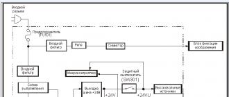
Design of phosphor LEDs

Diagram of one of the designs of a white LED. MPCB is a PCB with high thermal conductivity.
A modern phosphor light-emitting diode is a complex device that combines many original and unique technical solutions. An LED has several main elements, each of which performs an important, often more than one, function:
All LED structural elements are subject to thermal loads and must be selected taking into account their degree of thermal expansion. And an important condition for a good design is manufacturability and low cost of assembling an LED device and installing it into a lamp.
Brightness and quality of light
The most important parameter is not even the brightness of the LED, but its luminous efficiency, that is, the light output from each Watt of electrical energy consumed by the LED. The luminous efficiency of modern LEDs reaches 150-170 lm / W. The theoretical limit of the technology is estimated at 260-300 lm / W. When assessing, it is necessary to take into account that the efficiency of the LED-based luminaire is significantly lower due to the efficiency of the power supply, the optical properties of the diffuser, reflector and other structural elements. In addition, manufacturers often indicate the initial efficiency of the emitter at normal temperature. Whereas the temperature of the chip during operation is much higher. This leads to the fact that the real efficiency of the emitter is lower by 5 - 7%, and the luminaire is often twice as low.
The second equally important parameter is the quality of the light produced by the LED. There are three parameters to assess the quality of color rendering:
Phosphor LED based on ultraviolet emitter
In addition to the already widespread version of the combination of a blue LED and YAG, a design based on an ultraviolet LED is also being developed. A semiconductor material capable of emitting in the near ultraviolet region is coated with several layers of phosphor based on europium and zinc sulfide, activated by copper and aluminum. Such a mixture of phosphors gives re-emission maxima in the green, blue and red regions of the spectrum. The resulting white light has very good quality characteristics, but the conversion efficiency is still low.
Advantages and disadvantages of phosphor LEDs
Given the high cost of LED light sources compared to traditional lamps, there are compelling reasons to use these devices:
- The main advantage of white LEDs is their high efficiency. Low specific energy consumption allows them to be used in long-term operating sources of autonomous and emergency lighting.
- High reliability and long service life allow us to talk about possible savings on lamp replacement. In addition, the use of LED light sources in hard-to-reach places and outdoor conditions can reduce maintenance costs. Combined with high efficiency, there are significant cost savings when using LED lighting in some applications.
- Light weight and size of devices. LEDs are small in size and are suitable for use in hard-to-reach places and small-sized portable devices.
- The absence of ultraviolet and infrared radiation in the spectrum allows the use of LED lighting without harm to humans and for special purposes (for example, for illuminating rare books or other objects exposed to light).
- Excellent work at low temperatures without lowering, and often with an improvement in parameters. Most types of LEDs show greater efficiency and durability as temperatures drop, but power, control, and structural components can have the opposite relationship.
- LEDs are non-inertial light sources, they do not require warm-up or shutdown time, such as fluorescent lamps, and the number of on and off cycles does not negatively affect their reliability.
- Good mechanical strength allows LEDs to be used in harsh environments.
- Ease of power regulation by both duty cycle and supply current regulation without reducing the parameters of efficiency and reliability.
- Safe use, no danger of electric shock due to low supply voltage.
- Low fire hazard, the ability to use in an explosion hazard and fire hazard due to the absence of heating elements.
- Moisture resistance, resistance to aggressive environments.
- Chemical neutrality, no harmful emissions and no special requirements for disposal procedures.
But there are also disadvantages:
Lighting LEDs also have features inherent in all semiconductor emitters, taking into account which the most successful application can be found, for example, radiation directivity. The LED shines only in one direction without the use of additional reflectors and diffusers. LED luminaires are best suited for spot and directional lighting.
Prospects for the development of white LED technology
Technologies for the production of white LEDs suitable for lighting purposes are under active development. Research in this area is stimulated by heightened public interest. The potential for significant energy savings is attracting investment in process research, technology development and the search for new materials. Judging by the publications of manufacturers of LEDs and related materials, specialists in the field of semiconductors and lighting technology, we can outline the development paths in this area:
see also
Notes (edit)
- , p. 19-20
- Cree MC-E LEDs containing red, green, blue and white emitters. LED Professional. Archived
- Vishay VLMx51 LEDs containing red, orange, yellow and white emitters. LED Professional. Archived from the original on November 23, 2012. Retrieved November 10, 2012.
- Cree XB-D and XM-L multicolor LEDs. LED Professional. Archived from the original on November 23, 2012. Retrieved November 10, 2012.
- Cree XP-C LEDs containing six monochromatic emitters. LED Professional. Archived from the original on November 23, 2012. Retrieved November 10, 2012.
- Nikiforov S."S-class" semiconductor lighting technology // Components and technologies: magazine. - 2009. - No. 6. - S. 88-91.
- Truson P. Halvardson A. Benefits of RGB LEDs for Lighting // Components and technologies: magazine. - 2007. - No. 2.
- , p. 404
- Nikiforov S. Temperature in the life and operation of LEDs // Components and technologies: magazine. - 2005. - No. 9.
- LEDs for interior and architectural lighting (eng.). LED Professional. Archived from the original on November 23, 2012. Retrieved November 10, 2012.
- Siang Ling Oon LED solutions for architectural lighting systems // : magazine. - 2010. - No. 5. - S. 18-20.
- RGB LEDs for use in electronic signage (English). LED Professional. Archived from the original on November 23, 2012. Retrieved November 10, 2012.
- Turkin A. Gallium nitride as one of the promising materials in modern optoelectronics // Components and technologies: magazine. - 2011. - No. 5.
- High CRI LEDs. LED Professional. Archived from the original on November 23, 2012. Retrieved November 10, 2012.
- Cree's EasyWhite technology. LEDs Magazine. Archived from the original on November 23, 2012. Retrieved November 10, 2012.
- Nikiforov S., Arkhipov A. Features of determining the quantum yield of LEDs based on AlGaInN and AlGaInP at different current density through the emitting crystal // Components and technologies: magazine. - 2008. - No. 1.
- Nikiforov S. Now electrons can be seen: LEDs make electric current very visible // Components and technologies: magazine. - 2006. - No. 3.
- LEDs with a matrix arrangement of a large number of semiconductor chips. LED Professional. Archived from the original on November 23, 2012. Retrieved November 10, 2012.
- White LED Lifetime Archived November 23, 2012. Retrieved November 10, 2012.
- Types of LED defects and analysis methods. LED Professional. Archived from the original on November 23, 2012. Retrieved November 10, 2012.
- , p. 61, 77-79
- SemiLEDs LEDs. LED Professional. Archived from the original on November 23, 2012. Retrieved November 10, 2012.
- GaN-on-Si Silicon-Based LED Research Program. LED Professional. Retrieved November 10, 2012.
- Cree's isolated phosphor technology. LED Professional. Archived from the original on November 23, 2012. Retrieved November 10, 2012.
- Turkin A. Semiconductor LEDs: history, facts, prospects // Semiconductor lighting engineering: magazine. - 2011. - No. 5. - S. 28-33.
- Ivanov A.V., Fedorov A.V., Semenov S.M. Energy-saving lamps based on high-brightness LEDs // Energy supply and energy saving - regional aspect: XII All-Russian meeting: materials of reports. - Tomsk: SPB Graphics, 2011 .-- S. 74-77.
- , p. 424
- White LEDs with high light output for lighting needs. Phys.Org ™. Archived from the original on November 23, 2012. Retrieved November 10, 2012.
- Fundamentals of LED Lighting U.S. Department of Energy. Archived from the original on November 23, 2012. Retrieved November 10, 2012.
- Sharakshane A. Scales for assessing the quality of the spectral composition of light - CRI and CQS // Semiconductor lighting engineering: magazine. - 2011. - No. 4.
- Ultraviolet SemiLED LEDs with a wavelength of 390-420 nm. (English). LED Professional. Archived from the original on November 23, 2012. Retrieved November 10, 2012.
- , p. 4-5
- Nuventix Campaign Active Cooling Systems. LED Professional. Archived from the original on November 23, 2012. Retrieved November 10, 2012.
- N.P. Soschin Modern photoluminophores for efficient solid-state lighting devices. Conference materials. (rus.) (february 1, 2010). Archived
- O. E. Dudukalo, V. A. Vorobyov(Russian) (may 31, 2011). Archived from the original on October 27, 2012.
- Accelerated Temperature Degradation Tests for Phosphors. LED Professional. Archived from the original on November 23, 2012. Retrieved November 10, 2012.
- Research and Markets Releases New 2012 Report on LED Phosphor Materials. LED Professional. Archived from the original on December 10, 2012. Retrieved November 30, 2012.
- Intematix has introduced a set of phosphors for high-quality color reproduction. LED Professional. Archived from the original on November 23, 2012. Retrieved November 10, 2012.
- Lumi-tech offered SSE a phosphor for white LEDs. LED Professional. Archived from the original on November 23, 2012. Retrieved November 10, 2012.
- Red phosphorus from Intematix. LED Professional. Archived from the original on November 23, 2012. Retrieved November 10, 2012.
- Quantum Dot LEDs LED Professional. Archived from the original on November 23, 2012. Retrieved November 10, 2012.
- Osram 609nm red all-diode prototype with 61% efficiency. LED Professional. Archived from the original on November 23, 2012. Retrieved November 10, 2012.
- Transition to the GaN-on-Si structure. LED Professional. Archived from the original on November 23, 2012. Retrieved November 10, 2012.
- Tim whitaker Joint venture to make ZnSe white LEDs (December 6, 2002). Archived from the original on October 27, 2012. Retrieved November 10, 2012.
- , p. 426
Literature
- Schubert F.E. LEDs. - Moscow: Fizmatlit, 2008 .-- 496 p. - ISBN 978-5-9221-0851-5
- Weinert D. LED Lighting: A Handbook. - Philips, 2010 .-- 156 p. - ISBN 978-0-615-36061-4
Links
- U.S. Department of Energy website for LED lighting
- Led Professional. Scientific and technical journal about LEDs and LED lighting, Austria
- LEDs Magazine. Scientific and technical journal about LEDs and LED lighting. USA
- Semiconductor lighting technology. Russian magazine about LEDs and LED lighting
| Incandescent | Incandescent lamp Halogen lamp |
|---|---|
| Fluorescent | |
There are two common ways to achieve sufficient white light intensity with LEDs. The first is the combination in one LED package of chips of three primary colors - red, green and blue. By mixing these colors, a white color is obtained, in addition, by changing the intensity of the primary colors, any color shade is obtained that is used in the manufacture. The second way is to use a phosphor to convert the radiation from a blue or ultraviolet LED to white. A similar principle is used in fluorescent lamps. Currently, the second method is prevalent due to the low cost and higher light output of phosphor LEDs.
Phosphors
Phosphors (the term comes from the Latin lumen - light and the Greek phoros - carrying) are substances that can glow under the influence of various kinds of excitations. By the method of excitation, photoluminophores, X-ray phosphors, radioluminophores, cathodoluminophores, electroluminophores are distinguished. Some phosphors are of mixed types of excitation, for example, photo-, cathode- and electroluminophore ZnS · Cu. According to their chemical structure, organic phosphors are distinguished - organoluminophores, and inorganic - phosphors. Phosphorus that have a crystalline structure are called crystal phosphorus. The ratio of emitted to absorbed energy is called quantum yield.
The glow of the phosphor is determined by both the properties of the base substance and the presence of an activator (impurity). The activator creates luminescence centers in the base substance. The name of the activated phosphors consists of the name of the base and the activator, for example: ZnS · Cu, Co means the ZnS phosphor, activated with copper and cobalt. If the base is mixed, then the names of the bases are listed first, and then the activators, for example, ZnS, CdS · Cu, Co.
The appearance of luminescent properties in inorganic substances is associated with the formation of a phosphor base in the crystal lattice during the synthesis of structural and impurity defects. The energy exciting the phosphor can be absorbed both by the luminescent centers (activator or impurity absorption) and by the phosphor backbone (fundamental absorption). In the first case, absorption is accompanied either by the transition of electrons inside the electron shell to higher energy levels, or by the complete detachment of an electron from the activator (a "hole" is formed). In the second case, when energy is absorbed by the base, holes and electrons are formed in the base substance. Holes can migrate over the crystal and localize at luminescence centers. Radiation occurs as a result of the return of electrons to lower energy levels or during the recombination of an electron with a hole.
Phosphors, in which luminescence is associated with the formation and recombination of unlike charges (electrons and holes), are called recombination. They are based on semiconductor-type compounds. In these phosphors, the crystal lattice of the base is the medium in which the luminescence process develops. This makes it possible, by changing the composition of the base, to widely vary the properties of the phosphors. Changing the band gap when using the same activator smoothly changes the spectral composition of the radiation within wide limits. Depending on the application, different requirements are imposed on the parameters of the phosphor: type of excitation, excitation spectrum, emission spectrum, emission yield, time characteristics (glow rise time and afterglow duration). The greatest variety of parameters can be obtained for crystalline phosphors by changing the activators and the composition of the base.
The excitation spectrum of various photoluminophores is wide, from shortwave ultraviolet to infrared. The spectrum of radiation is also in the visible, infrared or ultraviolet regions. The emission spectrum can be wide or narrow and strongly depends on the concentration of the phosphor and activator, as well as on the temperature. According to the Stokes - Lommel rule, the maximum of the emission spectrum is shifted from the maximum of the absorption spectrum towards longer waves. In addition, the emission spectrum usually has a considerable width. This is due to the fact that part of the energy absorbed by the phosphor is dissipated in its lattice, turning into heat. A special place is occupied by "anti-Stokes" phosphors, which emit energy in a higher region of the spectrum.
The energy yield of the phosphor radiation depends on the type of excitation, its spectrum and the conversion mechanism. It decreases with increasing concentration of phosphor and activator (concentration quenching) and temperature (thermal quenching). The brightness of the glow increases from the beginning of excitation for a different period of time. The duration of the afterglow is determined by the nature of the transformation and the lifetime of the excited state. Organoluminophores have the shortest afterglow time, and crystalline phosphors have the longest.
A significant part of crystal phosphors are semiconducting materials with a band gap of 1-10 eV, the luminescence of which is caused by an impurity of an activator or crystal lattice defects. In fluorescent lamps, mixtures of crystal phosphors are used, for example, mixtures of MgWO4 and (ZnBe) 2 SiO4 · Mn] or single-component phosphors, for example calcium halophosphate activated with Sb and Mn. Phosphors for illumination purposes are selected so that their luminescence has a spectral composition close to the spectrum of daylight.
Organic phosphors can be of high yield and speed. The phosphor color can be matched to any visible part of the spectrum. They are used for luminescence analysis, production of luminescent inks, indicators, optical bleaching of fabrics, etc. Organic phosphors were produced in the USSR under the trademark luminors.
The phosphor in the process of operation is subject to changes in parameters over time. This process is called aging (degradation) of the phosphor. Aging is mainly due to physical and chemical processes both in the phosphor layer and on its surface, the emergence of nonradiative centers, absorption of radiation in the changed phosphor layer.
Phosphor in LED
White LEDs are most often made on the basis of a blue InGaN crystal and a yellow phosphor. The yellow phosphors used by most manufacturers are trivalent cerium-doped yttrium-aluminum garnet (YAG). The luminescence spectrum of this phosphor is characterized by a maximum wavelength of 530..560 nm. The long-wavelength part of the spectrum is longer than the short-wavelength part. Modification of the phosphor with the addition of gadolinium and gallium makes it possible to shift the maximum of the spectrum to the cold region (gallium) or to the warm (gadolinium).

The spectral data of the phosphor used in the Cree are interesting. Judging by the spectrum, in addition to YAG, a phosphor with a radiation maximum shifted to the red region is added to the composition of the white LED phosphor.

In contrast to fluorescent lamps, the phosphor used in LEDs has a longer service life, and the aging of the phosphor is mainly determined by the temperature. The phosphor is most often applied directly to the LED crystal, which becomes very hot. Other factors affecting the phosphor are significantly less important for the service life. Aging of the phosphor leads not only to a decrease in the brightness of the LED, but also to a change in the shade of its glow. With a strong degradation of the phosphor, the blue tint of the luminescence is clearly visible. This is due to a change in the properties of the phosphor, and with the fact that the intrinsic radiation of the LED chip begins to dominate in the spectrum. With the introduction of (remote phosphor) technology, the effect of temperature on the rate of phosphor degradation is reduced.
The strip with a maximum in the yellow area (the most common design). The radiation of the LED and phosphor, when mixed, give white light of various shades.
Collegiate YouTube
1 / 5
✪ Short white LEDs
✪ White LED vs Red Blue White LED Grow Test - Amazon Lights (Intro)
✪ Cool White Vs Neutral White LED "s In Flashlights (Thrunite TN12 Models)
✪ White LED vs Red / Blue LED Grow light Grow Test - Part 1 (Educational) 2016
✪ White LED vs Red Blue White LED Grow Test w / Time Lapse - Lettuce Ep.1
Subtitles
History of invention
The first semiconductor red emitters for industrial use were obtained by N. Holonyak in 1962. In the early 70s, yellow and green LEDs appeared. The light output of these, while still ineffective, devices reached the level of one lumen by 1990. In 1993, Shuji Nakamura, an engineer at Nichia, Japan, created the first high-brightness blue LED. Almost immediately, RGB LED devices appeared, since blue, red and green colors made it possible to obtain any color, including white. White phosphor LEDs first appeared in 1996. Subsequently, the technology developed rapidly, and by 2005 the luminous efficacy of LEDs reached a value of 100 lm / W or more. LEDs with various shades of glow appeared, the quality of light made it possible to compete with incandescent lamps and already traditional fluorescent lamps. The use of LED lighting devices began in everyday life, in indoor and outdoor lighting.
RGB LEDs
White light can be created by mixing LEDs of different colors. The most common trichromatic construction is from red (R), green (G) and blue (B) sources, although there are bichromatic, tetrachromatic and more multicolored variants. A multi-color LED, unlike other RGB semiconductor emitters (lamps, lamps, clusters), has one complete body, most often similar to a single-color LED. The LED chips sit next to each other and share a common lens and reflector. Since semiconductor chips have finite size and their own radiation patterns, such LEDs most often have uneven angular color characteristics. In addition, it is often not enough to set the design current to obtain the correct color ratio, since the luminous efficacy of each chip is not known in advance and is subject to changes during operation. To set the desired RGB shades, luminaires are sometimes equipped with special control devices.
The spectrum of an RGB LED is determined by the spectrum of its constituent semiconductor emitters and has a pronounced line shape. This spectrum is very different from that of the sun, hence the RGB LED color rendering index is low. RGB LEDs allow you to easily and within a wide range to control the color of the glow by changing the current of each LED included in the "triad", to adjust the color tone of the white light emitted by them right in the process of work - up to obtaining individual independent colors.
Multicolor LEDs have a temperature dependence of light output and color due to the different characteristics of the emitting chips that make up the device, which affects a slight change in the glow color during operation. The lifespan of a multicolor LED is determined by the longevity of the semiconductor chips, depends on the design, and most often exceeds the lifespan of phosphor LEDs.
Multicolor LEDs are mainly used for decorative and architectural lighting, electronic displays and video screens.
Phosphor LEDs
The combination of blue (more often), violet or ultraviolet (not used in mass production) semiconductor emitter and phosphor converter allows you to make an inexpensive light source with good characteristics. The most common design of such an LED contains a blue semiconductor chip of gallium nitride modified with indium (InGaN) and a phosphor with a maximum re-emission in the yellow region - yttrium-aluminum garnet doped with trivalent cerium (YAG). Part of the power of the initial radiation of the chip leaves the LED housing, scattering in the phosphor layer, the other part is absorbed by the phosphor and re-emitted in the region of lower energy values. The re-emission spectrum covers a wide area from red to green, but the resulting spectrum of such an LED has a pronounced dip in the green-blue-green area.
Depending on the composition of the phosphor, LEDs are produced with different color temperatures ("warm" and "cold"). By combining different types of phosphors, a significant increase in the color rendering index (CRI or R a) is achieved. For 2017, there are already LED panels for photography and filming, where color rendition is critical, but such equipment is expensive, and manufacturers are rare.
One of the ways to increase the brightness of phosphor LEDs while maintaining or even reducing their cost is to increase the current through the semiconductor chip without increasing its size - to increase the current density. This method is associated with a simultaneous increase in requirements for the quality of the chip itself and for the quality of the heat sink. With an increase in the current density, the electric fields in the volume of the active region decrease the light output. When the limiting currents are reached, since the sections of the LED chip with different impurity concentrations and different bandgap widths conduct current in different ways, local overheating of the chip sections occurs, which affects the light output and the durability of the LED as a whole. In order to increase the output power while maintaining the quality of spectral characteristics and thermal conditions, LEDs are produced containing clusters of LED chips in one package.
One of the most discussed topics in the field of polychrome LED technology is their reliability and durability. Unlike many other light sources, over time, an LED changes its characteristics of light output (efficiency), directional pattern, color shade, but rarely fails completely. Therefore, to estimate the useful life, for example, for lighting, the level of reduction in luminous efficiency to 70% of the original value (L70) is taken. That is, an LED whose brightness has decreased by 30% during operation is considered to be out of order. For LEDs used in decorative lighting, a dimming level of 50% (L50) is used as an estimate of the lifespan.
The lifespan of a phosphor LED depends on many parameters. In addition to the manufacturing quality of the LED assembly itself (the method of attaching the chip to the crystal holder, the method of attaching the current-carrying conductors, the quality and protective properties of the sealing materials), the life time mainly depends on the characteristics of the emitting chip itself and on the change in the properties of the phosphor over the course of operating time (degradation). Moreover, as numerous studies show, temperature is considered the main factor influencing the life of an LED.
Effect of temperature on LED lifespan
During operation, a semiconductor chip gives off part of the electrical energy in the form of radiation, and part in the form of heat. Moreover, depending on the efficiency of such a conversion, the amount of heat is about half or more for the most efficient radiators. The semiconductor material itself has a low thermal conductivity, in addition, the materials and construction of the case have a certain non-ideal thermal conductivity, which leads to the heating of the chip to high (for a semiconductor structure) temperatures. Modern LEDs operate at chip temperatures of 70-80 degrees. And a further increase in this temperature when using gallium nitride is unacceptable. High temperature leads to an increase in the number of defects in the active layer, leads to increased diffusion, and a change in the optical properties of the substrate. All this leads to an increase in the percentage of nonradiative recombination and absorption of photons by the chip material. The increase in power and durability is achieved by improving both the semiconductor structure itself (reducing local overheating) and by developing the design of the LED assembly, improving the cooling quality of the active region of the chip. Research is also being carried out with other semiconductor materials or substrates.
The phosphor is also exposed to high temperatures. With prolonged exposure to temperature, re-emitting centers are inhibited, and the conversion coefficient, as well as the spectral characteristics of the phosphor, deteriorate. In the first and some modern designs of polychrome LEDs, the phosphor is applied directly to the semiconductor material and the thermal effect is maximum. In addition to measures to reduce the temperature of the emitting chip, manufacturers use various methods to reduce the effect of the chip temperature on the phosphor. Insulated phosphor technologies and LED lamp designs that physically separate the phosphor from the emitter can increase the life of the light source.
The LED housing, made of optically transparent silicone plastic or epoxy resin, is subject to temperature aging and begins to fade and turn yellow over time, absorbing some of the energy emitted by the LED. Reflective surfaces also deteriorate when heated - they interact with other elements of the case, are subject to corrosion. All these factors together lead to the fact that the brightness and quality of the emitted light gradually decreases. However, this process can be successfully slowed down by providing efficient heat dissipation.
Design of phosphor LEDs
A modern phosphor light-emitting diode is a complex device that combines many original and unique technical solutions. An LED has several main elements, each of which performs an important, often more than one, function:
All LED structural elements are subject to thermal loads and must be selected taking into account their degree of thermal expansion. And an important condition for a good design is manufacturability and low cost of assembling an LED device and installing it into a lamp.
Brightness and quality of light
The most important parameter is not even the brightness of the LED, but its luminous efficiency, that is, the light output from each watt of electrical energy consumed by the LED. The luminous efficiency of modern LEDs reaches 190 lm / W. The theoretical limit of the technology is estimated at more than 300 lm / W. When assessing, it is necessary to take into account that the efficiency of the LED-based luminaire is significantly lower due to the efficiency of the power supply, the optical properties of the diffuser, reflector and other structural elements. In addition, manufacturers often indicate the initial efficiency of the emitter at normal temperature, while the temperature of the chip during operation is much higher. This leads to the fact that the real efficiency of the emitter is lower by 5-7%, and of the luminaire - often twice.
The second equally important parameter is the quality of the light produced by the LED. There are three parameters to assess the quality of color rendering:
Phosphor LED based on ultraviolet emitter
In addition to the already widespread version of the combination of a blue LED and YAG, a design based on an ultraviolet LED is also being developed. A semiconductor material capable of emitting in the near ultraviolet region is coated with several layers of phosphor based on europium and zinc sulfide, activated by copper and aluminum. Such a mixture of phosphors gives re-emission maxima in the green, blue and red regions of the spectrum. The resulting white light has very good quality characteristics, but the conversion efficiency is still low. There are three reasons for this [ ]: the first is due to the fact that the difference between the energy of the incident and emitted quanta during fluorescence is lost (turns into heat), and in the case of ultraviolet excitation, it is much greater. The second reason is that part of the UV radiation that is not absorbed by the phosphor does not participate in the creation of the luminous flux, unlike LEDs based on a blue emitter, and an increase in the thickness of the phosphor coating leads to an increase in the absorption of luminescence light in it. Finally, the efficiency of ultraviolet LEDs is significantly lower than the efficiency of blue ones.
Advantages and disadvantages of phosphor LEDs
Given the high cost of LED light sources compared to traditional lamps, there are compelling reasons to use these devices:
But there are also disadvantages:
Lighting LEDs also have features inherent in all semiconductor emitters, taking into account which the most successful application can be found, for example, radiation directivity. The LED shines only in one direction without the use of additional reflectors and diffusers. LED luminaires are best suited for spot and directional lighting.
Prospects for the development of white LED technology
Technologies for the production of white LEDs suitable for lighting purposes are under active development. Research in this area is stimulated by heightened public interest. The potential for significant energy savings is attracting investment in process research, technology development and the search for new materials. Judging by the publications of manufacturers of LEDs and related materials, specialists in the field of semiconductors and lighting technology, we can outline the development paths in this area:
see also
Notes (edit)
- , p. 19-20.
- Cree MC-E LEDs containing red, green, blue and white emitters Archived November 22, 2012.
- Vishay VLMx51 LEDs containing red, orange, yellow and white emitters(English). LED Professional. Retrieved November 10, 2012. Archived November 22, 2012.
- Cree XB-D and XM-L Multicolor LEDs(English). LED Professional. Retrieved November 10, 2012. Archived November 22, 2012.
- Cree XP-C LEDs containing six monochromatic emitters(English). LED Professional. Retrieved November 10, 2012. Archived November 22, 2012.
- Nikiforov S."S-class" semiconductor lighting technology // Components and technologies: magazine. - 2009. - No. 6. - S. 88-91.
- Truson P. Halvardson A. Advantages of RGB LEDs for lighting devices // Components and technologies: magazine. - 2007. - No. 2.
- , p. 404.
- Nikiforov S. Temperature in the life and operation of LEDs // Components and technologies: journal. - 2005. - No. 9.
- LEDs for interior and architectural lighting(English). LED Professional. Retrieved November 10, 2012. Archived November 22, 2012.
- Siang Ling Oon. LED solutions for architectural lighting systems // Semiconductor lighting technology: magazine. - 2010. - No. 5. - S. 18-20.
- RGB LEDs for use in electronic signage(English). LED Professional. Retrieved November 10, 2012. Archived November 22, 2012.
- High CRI LED Lighting | Yuji LED (unspecified) ... yujiintl.com. Retrieved 3 December 2016.
- Turkin A. Gallium nitride as one of the promising materials in modern optoelectronics // Components and technologies: journal. - 2011. - No. 5.
- High CRI LEDs(English). LED Professional. Retrieved November 10, 2012. Archived November 22, 2012.
- Cree EasyWhite Technology(English). LEDs Magazine. Retrieved November 10, 2012. Archived November 22, 2012.
- Nikiforov S., Arkhipov A. Features of determining the quantum yield of LEDs based on AlGaInN and AlGaInP at different current density through the emitting crystal // Components and technologies: journal. - 2008. - No. 1.
- Nikiforov S. Now electrons can be seen: LEDs make electric current very visible // Components and Technologies: Journal. - 2006. - No. 3.
- LEDs with a matrix arrangement of a large number of semiconductor chips(English). LED Professional. Retrieved November 10, 2012. Archived November 22, 2012.
- White LED Life(English). U.S. Department of Energy. Retrieved November 10, 2012. Archived November 22, 2012.
- Types of LED defects and methods of analysis(English). LED Professional. Retrieved November 10, 2012. Archived November 22, 2012.
- , p. 61, 77-79.
- SemiLEDs LEDs(English). LED Professional. Retrieved November 10, 2012. Archived November 22, 2012.
- GaN-on-Si Silicon-Based LED Research Program(English). LED Professional. Date of treatment November 10, 2012.
- Cree isolated phosphor technology(English). LED Professional. Retrieved November 10, 2012. Archived November 22, 2012.
- Turkin A. Semiconductor LEDs: history, facts, prospects // Semiconductor lighting technology: journal. - 2011. - No. 5. - S. 28-33.
- Ivanov A.V., Fedorov A.V., Semenov S.M. Energy-saving lamps based on high-brightness LEDs // Energy supply and energy saving - regional aspect: XII All-Russian meeting: materials of reports. - Tomsk: SPB Graphics, 2011 .-- S. 74-77.
- , p. 424.
- Reflectors for LEDs based on photonic crystals(English). Led Professional. Retrieved February 16, 2013. Archived March 13, 2013.
- XLamp XP-G3(English). www.cree.com. Retrieved May 31, 2017.
- White LEDs with high light output for lighting needs(English). Phys.Org ™. Retrieved November 10, 2012. Archived November 22, 2012.
The days when LEDs were used only as indicators for turning on devices are long gone. Modern LED devices can completely interchange incandescent lamps in household, industrial and. This is facilitated by the various characteristics of LEDs, knowing which you can choose the right LED analogue. The use of LEDs, given their basic parameters, opens up an abundance of possibilities in the field of lighting.
LED (denoted by LED, LED, LED in English) is a device based on an artificial semiconductor crystal. When an electric current is passed through it, the phenomenon of emission of photons is created, which leads to a glow. This luminescence has a very narrow spectrum range, and its color depends on the semiconductor material.

LEDs with red and yellow glow are made from inorganic semiconductor materials based on gallium arsenide, green and blue ones are made on the basis of indium gallium nitride. To increase the brightness of the luminous flux, various additives are used or a multilayer method is used, when a layer of pure aluminum nitride is placed between semiconductors. As a result of the formation of several electron-hole (p-n) transitions in one crystal, the brightness of its luminescence increases.
There are two types of LEDs: for indication and lighting. The former are used to indicate the inclusion of various devices in the network, as well as sources of decorative lighting. They are colored diodes placed in a translucent case, each of them has four leads. Devices emitting infrared light are used in devices for remote control of devices (remote control).
In the field of lighting, LEDs emitting white light are used. LEDs with cold white, neutral white and warm white glow are distinguished by color. There is a classification of LEDs used for lighting according to the method of installation. SMD LED marking means that the device consists of an aluminum or copper substrate on which a diode crystal is placed. The substrate itself is located in the housing, the contacts of which are connected to the contacts of the LED.

Another type of LED is designated OCB. In such a device, a plurality of crystals coated with a phosphor are placed on one board. Thanks to this design, a high luminescence brightness is achieved. This technology is used in production with a high luminous flux in a relatively small area. In turn, this makes the production of LED lamps the most affordable and inexpensive.
Note! Comparing lamps on SMD and COB LEDs, it can be noted that the former can be repaired by replacing a failed LED. If the COB LED lamp does not work, you will have to change the entire board with diodes.
LED characteristics
When choosing a suitable LED lamp for lighting, the parameters of the LEDs should be taken into account. These include supply voltage, power, operating current, efficiency (light output), glow temperature (color), radiation angle, dimensions, degradation period. Knowing the basic parameters, it will be possible to easily select devices for obtaining a particular illumination result.

LED current consumption
Typically, conventional LEDs have a current of 0.02A. However, there are LEDs rated at 0.08A. These LEDs include more powerful devices, in the device of which four crystals are involved. They are located in the same building. Since each of the crystals consumes 0.02A, in total one device will consume 0.08A.
The stability of the LED devices depends on the magnitude of the current. Even a slight increase in the current strength contributes to a decrease in the radiation intensity (aging) of the crystal and an increase in the color temperature. This ultimately leads to the fact that the LEDs begin to cast blue and fail prematurely. And if the indicator of the current strength increases significantly, the LED immediately burns out.
To limit the current consumption, current stabilizers for LEDs (drivers) are provided in the designs of LED lamps and luminaires. They convert the current, bringing it to the value required by the LEDs. In the case when it is required to connect a separate LED to the network, current-limiting resistors must be used. The calculation of the resistance of the resistor for the LED is performed taking into account its specific characteristics.
Helpful advice! To choose the right resistor, you can use the LED resistor calculator located on the Internet.

LED voltage
How do I know the voltage of the LEDs? The fact is that LEDs do not have a supply voltage parameter as such. Instead, the LED voltage drop characteristic is used, which means the amount of voltage at the output of the LED when the rated current is passed through it. The voltage value indicated on the package reflects exactly the voltage drop. Knowing this value, you can determine the voltage remaining on the crystal. It is this value that is taken into account in the calculations.
Given the use of different semiconductors for LEDs, the voltage for each of them can be different. How to find out how many Volts the LED is? It can be determined by the color of the glow of the devices. For example, for blue, green and white crystals, the voltage is about 3V, for yellow and red crystals - from 1.8 to 2.4V.
When using parallel connection of LEDs of identical rating with a voltage value of 2V, you may encounter the following: as a result of the spread of parameters, some emitting diodes will fail (burn out), while others will glow very weakly. This will happen due to the fact that with an increase in voltage even by 0.1V, an increase in the current passing through the LED is observed by 1.5 times. Therefore, it is so important to ensure that the current corresponds to the LED rating.

Luminous efficiency, angle of illumination and power of LEDs
Comparison of the luminous flux of diodes with other light sources is carried out, taking into account the strength of the radiation they emit. Devices measuring about 5 mm in diameter give 1 to 5 lm of light. While the luminous flux of a 100W incandescent lamp is 1000 lm. But when comparing, it must be borne in mind that the light of a conventional lamp is diffused, while that of an LED is directional. Therefore, the scattering angle of the LEDs must be taken into account.
The scattering angle of different LEDs can be from 20 to 120 degrees. When illuminated, LEDs provide brighter light in the center and reduce illumination towards the edges of the scattering angle. Thus, LEDs illuminate a specific space better while using less power. However, if it is required to increase the illumination area, diffusing lenses are used in the design of the luminaire.
How to determine the wattage of LEDs? To determine the power of an LED lamp required to replace an incandescent lamp, a factor equal to 8. So, you can replace a conventional 100W lamp with a LED device with a power of at least 12.5W (100W / 8). For convenience, you can use the data from the table of correspondence between the power of incandescent lamps and LED light sources:
| Incandescent lamp power, W | Corresponding power of LED luminaire, W |
| 100 | 12-12,5 |
| 75 | 10 |
| 60 | 7,5-8 |
| 40 | 5 |
| 25 | 3 |
When using LEDs for lighting, the efficiency indicator is very important, which is determined by the ratio of luminous flux (lm) to power (W). Comparing these parameters for different light sources, we find that the efficiency of an incandescent lamp is 10-12 lm / W, luminescent - 35-40 lm / W, LED - 130-140 lm / W.
Color temperature of LED sources
One of the important parameters of LED sources is the glow temperature. The units of this quantity are degrees Kelvin (K). It should be noted that all light sources are divided into three classes according to their glow temperature, among which warm white has a color temperature of less than 3300 K, day white - from 3300 to 5300 K and cold white over 5300 K.
Note! Comfortable perception of LED radiation by the human eye directly depends on the color temperature of the LED source.
The color temperature is usually indicated on the labeling of LED lamps. It is denoted by a four-digit number and the letter K. The choice of LED lamps with a specific color temperature directly depends on the characteristics of its application for lighting. The table below shows the options for using LED sources with different glow temperatures:
| LED color | Color temperature, K | Lighting use cases | |
| White | Warm | 2700-3500 | Lighting of household and office premises as the most suitable analogue of an incandescent lamp |
| Neutral (daytime) | 3500-5300 | Excellent color rendering of such lamps allows them to be used to illuminate workplaces in production. | |
| Cold | over 5300 | It is mainly used for street lighting, and is also used in the device of hand-held lights | |
| Red | 1800 | As a source of decorative and phyto-lighting | |
| Green | - | ||
| Yellow | 3300 | Lighting design of interiors | |
| Blue | 7500 | Illumination of surfaces in the interior, phyto-illumination | |
The wave-like nature of color allows the color temperature of LEDs to be expressed using wavelength. The marking of some LED devices reflects the color temperature precisely in the form of an interval of different wavelengths. Wavelength is designated λ and is measured in nanometers (nm).
Sizes of SMD LEDs and their characteristics
Considering the size of SMD LEDs, devices are classified into groups with different characteristics. The most popular LEDs with standard sizes 3528, 5050, 5730, 2835, 3014 and 5630. Characteristics of SMD LEDs vary depending on the size. So, different types of SMD LEDs differ in brightness, color temperature, power. In the LED markings, the first two digits show the length and width of the fixture.

Main parameters of SMD 2835 LEDs
The main characteristics of 2835 SMD LEDs include an increased radiation area. Compared to the SMD 3528, which has a round working surface, the emitting area of the SMD 2835 is rectangular, which contributes to a higher light output with a lower element height (about 0.8 mm). The luminous flux of such a device is 50 lm.
The body of SMD 2835 LEDs is made of heat-resistant polymer and can withstand temperatures up to 240 ° C. It should be noted that the degradation of radiation in these elements is less than 5% during 3000 hours of operation. In addition, the device has a fairly low thermal resistance of the crystal-substrate junction (4 C / W). The maximum operating current is 0.18A, the crystal temperature is 130 ° C.
By the color of the glow, warm white is distinguished with a glow temperature of 4000 K, day white - 4800 K, pure white - from 5000 to 5800 K and cold white with a color temperature of 6500-7500 K. It should be noted that the maximum luminous flux is for devices with cold white glow, minimal - for LEDs of warm white color. The design of the device has enlarged contact pads, which contributes to better heat dissipation.
Helpful advice! SMD 2835 LEDs can be used for any type of installation.

Characteristics of SMD 5050 LEDs
Three LEDs of the same type are placed in the construction of the SMD 5050 case. Blue, red and green LED sources have technical characteristics similar to SMD 3528 crystals. The operating current of each of the three LEDs is 0.02A, therefore the total current of the entire device is 0.06A. To ensure that the LEDs do not fail, it is recommended not to exceed this value.
LED devices SMD 5050 have a forward voltage of 3-3.3V and a luminous efficiency (network flux) of 18-21 lm. The power of one LED is the sum of three values of the power of each crystal (0.7W) and is 0.21W. The glow color emitted by the devices can be white in all shades, green, blue, yellow and multicolor.
The close arrangement of LEDs of different colors in one SMD 5050 package made it possible to realize multi-color LEDs with separate control for each color. To regulate luminaires using SMD 5050 LEDs, controllers are used, so that the glow color can be smoothly changed from one to another after a given amount of time. Typically, such devices have several control modes and can adjust the brightness of the LEDs.

Typical Characteristics of SMD 5730 LED
SMD 5730 LEDs are modern representatives of LED devices, the case of which has a geometric dimensions of 5.7x3 mm. They belong to ultra-bright LEDs, the characteristics of which are stable and qualitatively different from the parameters of their predecessors. Manufactured using new materials, these LEDs are characterized by increased power and highly efficient luminous flux. In addition, they can work in high humidity conditions, are resistant to temperature extremes and vibration, and have a long service life.
There are two types of devices: SMD 5730-0.5 with a power of 0.5W and SMD 5730-1 with a power of 1W. A distinctive feature of the devices is the ability to operate on a pulsed current. The value of the rated current of the SMD 5730-0.5 is 0.15A, during pulse operation, the device can withstand a current strength of up to 0.18A. This type of LED provides a luminous flux of up to 45 lm.
SMD 5730-1 LEDs operate at a constant current of 0.35A, in a pulsed mode - up to 0.8A. The light output efficiency of such a device can be up to 110 lumens. Thanks to a heat-resistant polymer, the body of the device can withstand temperatures up to 250 ° C. The dispersion angle of both types of SMD 5730 is 120 degrees. The degradation rate of luminous flux is less than 1% when used for 3000 hours.

Characteristics of Cree LEDs
The Cree company (USA) is engaged in the development and production of superbright and most powerful LEDs. One of the groups of Cree LEDs is represented by the Xlamp series of devices, which are divided into single-chip and multi-chip. One of the features of single-chip sources is the distribution of radiation along the edges of the device. This innovation has made it possible to produce luminaires with a large beam angle using a minimum number of crystals.
In the series of LED sources XQ-E High Intensity, the angle of illumination is from 100 to 145 degrees. Having small geometric dimensions of 1.6x1.6 mm, the power of super-bright LEDs is 3 Volts, and the luminous flux is 330 lm. This is one of the newest developments of the Cree company. All LEDs, the design of which is developed on the basis of one crystal, have high-quality color rendering within the CRE 70-90 range.
Related article:
How to make or fix an LED garland yourself. Prices and basic characteristics of the most popular models.
Cree has released several versions of multichip LED fixtures with the latest power types from 6 to 72 volts. Multichip LEDs are divided into three groups, which include devices with high voltage, power up to 4W and above 4W. In sources up to 4W, 6 crystals are collected in MX and ML packages. The scattering angle is 120 degrees. You can buy Cree LEDs of this type with a warm white and cold glow color.
Helpful advice! Despite the high reliability and quality of light, powerful LEDs of the MX and ML series can be bought at a relatively low price.
The group over 4W includes LEDs from several crystals. The largest in the group are 25W devices presented by the MT-G series. The company's novelty is the LEDs of the XHP model. One of the large LED devices has a 7x7 mm housing, its power is 12 W, and the luminous efficiency is 1710 lumens. High voltage LEDs combine small size and high light output.

LED connection diagrams
There are certain rules for connecting LEDs. Taking into account that the current passing through the device moves in only one direction, for a long and stable operation of LED devices, it is important to take into account not only a certain voltage, but also the optimal current value.
Diagram of connecting the LED to the 220V network
Depending on the power source used, there are two types of schemes for connecting LEDs to 220V. In one of the cases it is used with a limited current, in the second - a special, stabilizing voltage. The first option takes into account the use of a special source with a certain current strength. A resistor is not required in this circuit, and the number of connected LEDs is limited by the driver's power.
Two types of pictograms are used to indicate LEDs in the diagram. Above each schematic depiction of them, there are two small parallel arrows pointing up. They symbolize the bright glow of the LED device. Before connecting the LED to 220V using the power supply, you must include a resistor in the circuit. If this condition is not met, this will lead to the fact that the working life of the LED will be significantly reduced or it will simply fail.

If you use a power supply when connecting, then only the voltage will be stable in the circuit. Given the low internal resistance of the LED device, turning it on without a current limiter will result in the device burning. That is why a corresponding resistor is introduced into the LED switching circuit. It should be noted that resistors come in different ratings, so they should be calculated correctly.
Helpful advice! A negative aspect of the circuits for switching on the LED to a 220 Volt network using a resistor is the dissipation of high power when it is required to connect a load with increased current consumption. In this case, the resistor is replaced with a quenching capacitor.
How to calculate the resistance for an LED
When calculating the resistance for an LED, they are guided by the formula:
U = IхR,
where U is voltage, I is current strength, R is resistance (Ohm's law). Let's say you need to connect an LED with the following parameters: 3V - voltage and 0.02A - current. So that when the LED is connected to 5 Volts on the power supply, it does not fail, you need to remove the extra 2V (5-3 = 2V). To do this, you need to include a resistor with a certain resistance in the circuit, which is calculated using Ohm's law:
R = U / I.

Thus, the ratio of 2V to 0.02A will be 100 ohms, i.e. this is exactly what a resistor is needed.
It often happens that given the parameters of the LEDs, the resistance of the resistor has a non-standard value for the device. Such current limiters cannot be found at the point of sale, for example, 128 or 112.8 ohms. Then you should use resistors, the resistance of which is the nearest greater value than the calculated one. In this case, the LEDs will not function at full strength, but only by 90-97%, but this will be invisible to the eye and will have a positive effect on the resource of the device.
There are many options for calculators for calculating LEDs on the Internet. They take into account the main parameters: voltage drop, rated current, output voltage, number of devices in the circuit. By setting the parameters of LED devices and current sources in the form field, you can find out the corresponding characteristics of the resistors. Online resistor calculations for LEDs also exist to determine the resistance of color-coded current limiters.
Diagrams of parallel and series connection of LEDs
When assembling structures from several LED devices, circuits for switching LEDs into a 220 Volt network with a serial or parallel connection are used. In this case, for a correct connection, it should be borne in mind that when the LEDs are connected in series, the required voltage is the sum of the voltage drops of each device. While when the LEDs are connected in parallel, the current strength is added.

If the circuits use LED devices with different parameters, then for stable operation it is necessary to calculate the resistor for each LED separately. It should be noted that no two LEDs are exactly alike. Even devices of the same model have slight differences in parameters. This leads to the fact that when you connect a large number of them in a series or parallel circuit with one resistor, they can quickly degrade and fail.
Note! When using one resistor in a parallel or series circuit, only LED devices with identical characteristics can be connected.
The discrepancy in the parameters when several LEDs are connected in parallel, say 4-5 pcs., Will not affect the operation of the devices. And if you connect a lot of LEDs to such a circuit, it will be a bad decision. Even if LED sources have a slight variation in characteristics, this will lead to the fact that some devices will emit bright light and burn out quickly, while others will glow dimly. Therefore, when connecting in parallel, always use a separate resistor for each device.
With regard to the series connection, there is an economical consumption here, since the entire circuit consumes an amount of current equal to the consumption of one LED. In a parallel circuit, the consumption is the sum of the consumption of all LED sources included in the circuit included in the circuit.

How to connect LEDs to 12 Volts
In the design of some devices, resistors are provided even at the manufacturing stage, which makes it possible to connect LEDs to 12 Volts or 5 Volts. However, such devices are not always available commercially. Therefore, in the circuit for connecting LEDs to 12 volts, a current limiter is provided. The first step is to find out the characteristics of the connected LEDs.
Such a parameter as the forward voltage drop for typical LED devices is about 2V. The rated current of these LEDs is 0.02A. If you need to connect such an LED to 12V, then the "extra" 10V (12 minus 2) must be extinguished with a limiting resistor. Ohm's law can be used to calculate the resistance for it. We get that 10 / 0.02 = 500 (Ohm). Thus, a 510 ohm resistor is needed, which is the closest in the E24 range of electronic components.
For such a scheme to work stably, it is also necessary to calculate the power of the limiter. Using the formula, based on which the power is equal to the product of voltage and current, we calculate its value. A voltage of 10V is multiplied by a current of 0.02A and we get 0.2W. Thus, a resistor is required, the standard power rating of which is 0.25W.

If it is necessary to include two LED devices in the circuit, then it should be borne in mind that the voltage falling on them will already be 4V. Accordingly, for the resistor, it remains to extinguish not 10V, but 8V. Therefore, further calculation of the resistance and power of the resistor is done based on this value. The location of the resistor in the circuit can be provided anywhere: from the side of the anode, cathode, between the LEDs.
How to check an LED with a multimeter
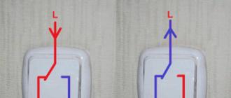
One way to check the working status of the LEDs is by testing with a multimeter. Such a device can diagnose LEDs of any design. Before checking the LED with a tester, the switch of the device is set in the "continuity" mode, and the probes are applied to the terminals. When the red probe is closed to the anode, and the black one to the cathode, the crystal should emit light. If the polarity is reversed, the display should show the reading "1".
Helpful advice! Before testing the LED for operability, it is recommended to dim the main lighting, since during testing the current is very low and the LED will emit light so weakly that you might not notice it under normal lighting.

You can test LED devices without using probes. To do this, in the holes located in the lower corner of the device, the anode is inserted into the hole with the "E" symbol, and the cathode - with the "C" indicator. If the LED is operational, it should light up. This test method is suitable for LEDs with sufficiently long solder-free pins. The position of the switch is irrelevant for this test method.
How to check LEDs with a multimeter without unsoldering? To do this, you need to solder pieces from a regular paper clip to the tester probes. As insulation, a textolite gasket is suitable, which is laid between the wires, after which it is processed with electrical tape. The output is a kind of adapter for connecting the probes. Staples are springy and securely fixed in the connectors. In this form, you can connect the probes to the LEDs without unsoldering them from the circuit.
What can be done from LEDs with your own hands
Many radio amateurs practice assembling various LED structures with their own hands. Self-assembled products are not inferior in quality, and sometimes even surpass their counterparts in production. These can be color music devices, flashing LED designs, DIY running lights on LEDs, and much more.

DIY current stabilizer assembly for LEDs
In order for the LED resource not to run out earlier than the due date, it is necessary that the current flowing through it has a stable value. It is known that red, yellow and green LEDs can handle increased current loads. While blue-green and white LED-sources, even with a slight overload, burn out in 2 hours. Thus, for normal operation of the LED, it is necessary to resolve the issue with its power supply.
If you assemble a chain of LEDs connected in series or in parallel, then you can provide them with identical radiation if the current passing through them has the same strength. In addition, reverse current pulses can negatively affect the life of LED sources. To prevent this from happening, it is necessary to include a current stabilizer for LEDs in the circuit.
The quality features of LED lamps depend on the driver used - a device that converts the voltage into a stabilized current with a specific value. Many radio amateurs assemble a power supply circuit for LEDs from 220V with their own hands based on the LM317 microcircuit. Elements for such an electronic circuit are inexpensive and such a regulator is easy to design.

When using a current stabilizer on the LM317 for LEDs, the current is regulated within 1A. A rectifier based on LM317L stabilizes the current up to 0.1A. The device uses only one resistor in the circuit. It is calculated using the online LED resistance calculator. Available devices are suitable for power supply: power supplies from a printer, laptop or other consumer electronics. It is not profitable to assemble more complex schemes on your own, since it is easier to purchase them ready-made.
DIY LED DRL
The use of daytime running lights (DRL) on cars significantly increases the visibility of the car in daylight by other road users. Many car enthusiasts practice self-assembly of DRLs using LEDs. One of the options is a DRL device of 5-7 LEDs with a power of 1W and 3W for each block. If you use less powerful LED sources, the luminous flux will not meet the standards for such lights.
Helpful advice! When making DRL with your own hands, take into account the requirements of GOST: the luminous flux is 400-800 Kd, the glow angle in the horizontal plane is 55 degrees, in the vertical plane - 25 degrees, the area is 40 cm².

For the base, you can use an aluminum profile board with pads for attaching LEDs. The LEDs are fixed to the board with a heat conductive adhesive. Optics are selected in accordance with the type of LED sources. In this case, lenses with a glow angle of 35 degrees are suitable. Lenses are installed on each LED separately. The wires are brought out in any convenient direction.
Next, a housing for DRL is made, which serves as a radiator at the same time. To do this, you can use a U-shaped profile. The finished LED module is placed inside the profile, fastened with screws. All free space can be filled with transparent silicone-based sealant, leaving only the lenses on the surface. Such a coating will serve as moisture protection.
The DRL is connected to the power supply with the obligatory use of a resistor, the resistance of which is pre-calculated and checked. Connection methods may vary depending on the car model. Connection diagrams can be found on the Internet.

How to make the LEDs flash
The most popular off-the-shelf flashing LEDs are potential-controlled devices. The flashing of the crystal occurs due to a change in the power supply at the terminals of the device. Thus, a two-color red-green LED device emits light depending on the direction of the current passing through it. The flashing effect of an RGB LED is achieved by connecting three separate control pins to a specific control system.
But you can make an ordinary one-color LED blinking, having a minimum of electronic components in your arsenal. Before making a blinking LED, you need to choose a working circuit that is simple and reliable. A flashing LED circuit can be used, which will be powered from a 12V source.
The circuit consists of a low-power transistor Q1 (silicon high-frequency KTZ 315 or its analogs are suitable), a resistor R1 820-1000 Ohm, a 16-volt capacitor C1 with a capacity of 470 μF and an LED source. When the circuit is turned on, the capacitor is charged to 9-10V, after which the transistor opens for a moment and gives the accumulated energy to the LED, which starts blinking. This scheme can be implemented only when powered from a 12V source.

A more advanced circuit can be assembled that works by analogy with a transistor multivibrator. The circuit includes transistors KTZ 102 (2 pcs.), Resistors R1 and R4 of 300 Ohm each to limit the current, resistors R2 and R3 of 27000 Ohm to set the base current of the transistors, 16-volt polar capacitors (2 pcs. With a capacity of 10 μF) and two LED sources. This circuit is powered by a 5V constant voltage source.
The circuit works on the principle of "Darlington pair": capacitors C1 and C2 are alternately charged and discharged, which causes the opening of a particular transistor. When one transistor is giving energy to C1, one LED lights up. Further, C2 is smoothly charged, and the base current VT1 decreases, which leads to the closure of VT1 and the opening of VT2 and another LED lights up.
Helpful advice! If you use a supply voltage higher than 5V, you will need to use resistors with a different rating to prevent damage to the LEDs.

DIY assembly of color music on LEDs
To implement fairly complex color music schemes on LEDs with your own hands, you must first figure out how the simplest color music scheme works. It consists of one transistor, resistor and LED device. Such a circuit can be powered from a source with a rating of 6 to 12V. The operation of the circuit is due to cascade amplification with a common emitter (emitter).
The VT1 base receives a signal with varying amplitude and frequency. In the event that the signal fluctuations exceed a predetermined threshold, the transistor opens and the LED lights up. The disadvantage of this scheme is the dependence of the blinking on the degree of the sound signal. Thus, the effect of color music will appear only at a certain degree of sound volume. If the sound is increased. the LED will be on all the time, and when decreasing, it will flash slightly.
To achieve a full effect, a color music scheme is used on LEDs with a division of the sound range into three parts. The circuit with a three-channel sound transducer is powered by a 9V source. A huge number of color music schemes can be found on the Internet at various forums of radio amateurs. These can be color music schemes using a single-color strip, RGB-LED strip, as well as schemes for smoothly switching on and off LEDs. Also on the network you can find diagrams of running lights on LEDs.

DIY LED voltage indicator design
The voltage indicator circuit includes a resistor R1 (variable resistance 10 kOhm), resistors R1, R2 (1 kOhm), two transistors VT1 KT315B, VT2 KT361B, three LEDs - HL1, HL2 (red), HLЗ (green). X1, X2 - 6-volt power supplies. In this circuit, it is recommended to use LED devices with a voltage of 1.5V.
The operation algorithm of the homemade LED voltage indicator is as follows: when voltage is applied, the central LED source is green. In the event of a voltage drop, the red LED on the left turns on. Increasing the voltage causes the red LED on the right to light up. With the resistor in the middle position, all transistors will be in the closed position, and the voltage will go only to the central green LED.
The opening of the transistor VT1 occurs when the slider of the resistor is moved up, thereby increasing the voltage. In this case, the supply of voltage to HL3 stops, and it is supplied to HL1. When you move the slider down (lowering the voltage), the transistor VT1 closes and VT2 opens, which will give power to the HL2 LED. With a slight delay, LED HL1 will go out, HL3 will flash once and HL2 will light up.

Such a circuit can be assembled using radio components from obsolete technology. Some people assemble it on a textolite board, observing a 1: 1 scale with the dimensions of the parts so that all the elements can fit on the board.
The unlimited potential of LED lighting makes it possible to independently design various lighting devices from LEDs with excellent characteristics and fairly low cost.