SATA(Serial -ATA, SerialAdvancedTechnologyAttachment) - a type of computer bus interface designed to connect devices, optical drives to the bus, and others.
It was developed and presented in 2003 year, as a replacement for the now obsolete interfaceATA(AT Attachment ), also known asIDE. Later, ATAwas renamed toPATA(Parallel ATA , for better recognition and avoid confusion.
An organization calledSATA —IO (Sata international organization ), which is responsible for the development, support, and publication of new specifications for bothSATAso for SAS (Serial Attached SCSI ).

Benefits the new interface compared to the old one was like physical: reduced dimensions of connectors, loops and fewer contact legs ( 7 vs 40); like that technical: native support for hot replacements"(Replacing an inactive device), faster data transfer at higher speedsincreased queue efficiency input / output commands (I O) Later, with the advent of the regime, technology support appeared.
Theoretically, the serial port is slower than the parallel, but the speed increase was achieved thanks to high frequency operation. We managed to increase the frequency due to the absence of the need for data synchronization, as well as a greater cable security from interference (thicker conductor, less interference).
AT 2008
year, more 90%
new desktop computers used to connect peripheralsSATAconnector PATA you can still get it, but they are sold only to maintain compatibility with old drives and motherboards.
RevisionsSATA :
SATA 1. x
The first revision of the interface provides for the frequency of operation 1.5 GHzthat provides bandwidth 1.5 Gbps. About 20%
taken away to the needs of a coding system like 8
b 10 bwhere in every 10 bit invested yet 2 bits service information. Thus, the maximum speed is 1.2 Gbps (150 Mb / s) It's quite a bit faster than the fastest.PATA/133
but much better performance is achieved in modeAHCIwhere support worksNCQ (Native command queuing
) This greatly improves performance in multi-threaded tasks, but not all controllers support AHCI on the first version SATA.
SATA 2. x
The frequency of operation has been increased to 3.0 GHzthat increased throughput to 3.0 Gbps. Effective throughput equals 2.4Gbps (300 Mb /
c), i.e. 2 times higher than that ofSATA 1
. Compatibility
between the first and second revision preserved. The interface cables were also kept the same and fully compatible between themselves.
SATA 3.0

In July 2008 SATA - IO introduced specificationsSATA 3.0 with bandwidth 6 Gbps / from. Full 3.0 The standard was released in May 2009.
Effective throughput amounted to 600 Mb / s, and the frequency of functioning 6.0 GHz (that is, only the frequency is raised). Compatibility preserved both in the data transfer method and in the connectors and wires; improved power management.
The main area of \u200b\u200bapplication where such bandwidth was required -SSD (solid state) drives. For hard drives, this bandwidth was not required. The gain for them was at a higher data rate from cache (DRAM - cache) of the disk's memory.
SATA 3.1
Changes:
- · Appeared mSATA, a similar (and compatible) connector for solid state drives and laptop devices, combined with the supply line low power.
- · Standard optical drives, larger do not consume energy (at all) in mode just me.
- · Added hardware queue command that improves performance and durability SSD.
- · Hardware features identificationdefining opportunities devices.
- · Advanced nutrition managementthat allows devices connected via SATA 3.1 to consume less energy.
A Advanced H Ost C ontroller I nterface

Open host interface proposed byIntelbecome a standard. Is an more preferred device interfaceSATA. Allows the use of such commandsSATAas Hot plug (hot swap)NCQ (Native command queuing ) If in settings motherboard not setAHCIthen used emulation IDE»And new features are not supportedSATA. Versions Windows (almost all) installed in modeIDEwill not be able to start if you start the system with the settingsAHCI. This will require special drivers AHCI, installed in the system.
e— SATA

Portable kind of interfaceSatawhose transfer rate is higher than that of 2.0 and IEEE 1394 .
Major changes compared toSATA:
- · Connectors shieldedand more resistant for reusable connection.
- · Modified loss compensation signals that allowed increase maximum length cable up to 2 meters.
- · Requires connection 2 connectors single power, second interface.
eSATAp

- advanced connectore - Satabut with food from the connector. Thereby,e - Satabecomes a full-fledged portable and universal interface. With exit USB 3.0turned out to be deprived of attention, since USB offers simpler implementation.
mSATA

–
PCI—
e
like interface introduced in September 2009
of the year. Intended for miniature devices (solid state drives, portable hard drives). It is also planned to use in portable devices such as laptops, and other. Devices with this interface may have very tiny sizessimilar to expansion cards for laptops (for example).
Exists adapters Pata— Sata , Sata— Pata.

They allow you to connect devices with different interfaces that emulated by a special controller on the adapter. The vast majority of adapters require additional food from the power supply unit (usually of type " molex" or 5vdrive connector).
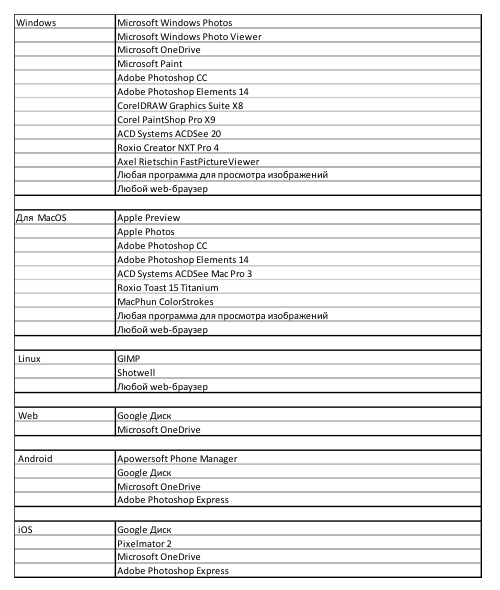
A drive interface is a set of electronics that provides the exchange of information between a device controller (cache buffer) and a computer. Currently, IBM-PC desktops, more often than others, use two types of ATAPI interfaces - AT Attachment Packet Interface (Integrated Drive Electronics - IDE, Enhanced Integrated Drive Electronics - EIDE) and SCSI (Small Computers System Interface).
InterfaceIDE It was developed as an inexpensive and productive alternative to high-speed ESDI and SCSI interfaces. Interface designed to connect two disk devices. A distinctive feature of disk devices working with the IDE interface is that the disk drive controller itself is located on the drive board itself, along with a built-in internal cache buffer. This design greatly simplifies the device of the interface card itself and makes it possible to place it not only on a separate adapter board that is inserted into the system bus connector, but also integrate it directly on the computer's motherboard. The interface is characterized by extreme simplicity, high speed, small size and relative low cost.
Drive adapter interface diagrams in the IDE
Today, the IDE interface has been replaced by the brainchild of Western Digital - Enhanced IDE, or EIDE for short. Now this is the best option for the vast majority of desktop systems. EIDE hard drives are noticeably cheaper than similar in capacity SCSI disks and in single-user systems are not inferior to them in performance, and most motherboards have an integrated dual-channel controller for connecting four devices. What is new in the Enhanced IDE compared to the IDE?
Firstly, it is a large disk capacity. If the IDE did not support drives over 528 megabytes, then EIDE supports volumes up to 8.4 gigabytes per controller channel.
Secondly, more devices are connected to it - four instead of two. Previously, there was only one controller channel to which two IDE devices could be connected. Now there are two such channels. The main channel, which usually stands on the high-speed local bus and auxiliary.
Thirdly, the ATAPI (AT Attachment Packet Interface) specification appeared, which makes it possible to connect not only hard disks to this interface, but also other devices - streamers and CD-ROM drives.
Fourth, productivity has improved. Drives with an IDE interface were characterized by a maximum data transfer rate of 3 megabytes per second. EIDE hard drives support several new communication modes. These include PIO (Programmed Input / Output) Mode 3 and 4, which provide data rates of 11.1 and 16.6 megabytes per second, respectively. Programmable I / O is a way of transferring data between the controller of a peripheral device and the computer’s main memory using data transfer commands and I / O ports of the central processor.
Fifth, the Direct Memory Access mode is supported - Multiword Mode 1 DMA (Direct Memory Access) or Multiword Mode 2 DMA and Ultra DMA, which support data exchange in exclusive mode (that is, when the I / O channel has been serving only one for some time device). DMA is another way of transferring data from a peripheral device controller to the computer’s RAM; it differs from PIO in that the PC’s central processor is not used and its resources remain free for other tasks. Peripheral devices are served by a special DMA controller. The speed in this case reaches 13.3 and 16.6 megabytes per second, and when using Ultra DMA and the corresponding bus driver - 33 megabytes per second. EIDE controllers use the PIO mechanism in the same way as some SCSI adapters do, but high-speed SCSI adapters work only according to the DMA method.
In the sixth, the system of commands for controlling the device, transmitting data and diagnostics was expanded, the cache buffer for data exchange was increased, and the mechanics were significantly improved.
Instead of the EIDE specification, Seagate and Quantum use the Fast ATA specification for drives supporting PIO Mode 3 and DMA Mode 1, while those operating in PIO Mode 4 and DMA Mode 2 are designated Fast ATA-2.
Intelligent multi-function interfaceSCSI was developed back in the late 70s as a device for interfacing a computer and an intelligent disk drive controller. The SCSI interface is universal and defines a data bus between the central processor and several external devices that have their own controller. In addition to the electrical and physical parameters, commands are also determined by which devices connected to the bus communicate with each other. The SCSI interface does not define in detail the processes on both sides of the bus and is a pure interface. The SCSI interface supports a much wider range of peripherals and is standardized by ANSI (X3.131-1986).
Today, two standards are mainly used - SCSI-2 and Ultra SCSI. In Fast SCSI-2 mode, the data transfer rate reaches 10 megabytes per second when using the 8-bit bus and up to 20 megabytes with the 16-bit Fast Wide SCSI-2 bus. The later Ultra SCSI standard is even more powerful - 20 megabytes per second for the 8-bit bus and 40 megabytes for the 16-bit bus. The latest SCSI-3 has a larger set of commands, but the performance remains at the same level. All applicable standards are compatible with previous versions.

Pairing external devices in the SCSI interface
from top to bottom, that is, you can connect old SCSI devices to SCSI-2 and Ultra SCSI adapters. SCSI-Wide, SCSI-2, SCSI-3 - standards for modifying the SCSI interface, developed by the ANSI committee. The general concept of improvements is aimed at increasing the bus width to 32, with an increase in the length of the connecting cable and maximum data transfer rate while maintaining compatibility with SCSI. This is the most flexible and standardized type of interface used to connect 7 or more peripherals equipped with a SCSI interface controller. The SCSI interface remains quite expensive and the highest performance of the family of peripherals for personal computers, and to connect a drive with a SCSI interface, you must additionally install an adapter, because few motherboards have an integrated SCSI adapter.
A hard disk is a simple and small “box” with a look that stores huge amounts of information in the computer of any modern user.
It seems to be just that from the outside: a fairly straightforward little thing. It is rare that when recording, deleting, copying and other actions with files of various importance, one thinks about the principle of interaction between a hard disk and a computer. And more precisely - directly with the motherboard itself.
How these components are connected into a single trouble-free operation, how the hard drive itself is arranged, what kind of connection connectors it has and what each of them is for is key information about the familiar storage device.
HDD interface
This term can correctly be called interaction with the motherboard. The word itself has a much broader meaning. For example, the program interface. In this case, the part is meant that provides a way of human interaction with software (convenient “friendly” design).
However, there is discord. In the case of the HDD and the motherboard, it does not present a pleasant graphic design for the user, but a set of special lines and data transfer protocols. These components are connected to each other using a loop cable - cable with inputs at both ends. They are designed to connect to ports on the hard disk and the motherboard.
In other words, the entire interface on these devices is two cables. One is connected to the hard drive power connector from one end and to the computer’s PSU itself from the other. And the second of the loops connects the HDD to the motherboard.
How in the old days connected a hard drive - IDE connector and other remnants of the past
The very beginning, after which more advanced HDD interfaces appear. Ancient by today's standards appeared on the market around the 80s of the last century. The IDE literally translates to "embedded controller."
Being a parallel data interface, it is also called ATA - however, over time, the new SATA technology appeared and gained huge popularity in the market, as the standard ATA was renamed to PATA (Parallel ATA) to avoid confusion.

Extremely slow and very crude in terms of its technical capabilities, this interface in the years of its popularity could pass from 100 to 133 megabytes per second. And only in theory, since in real practice these indicators were even more modest. Of course, newer interfaces and hard drive connectors will show a noticeable lag IDE from modern developments.
Do you think you should not play down the attractive sides? Older generations will probably remember that the technical capabilities of PATA allowed servicing two HDDs at once with the help of only one cable connected to the motherboard. But the line capacity in this case was similarly distributed in half. And this is not mentioning the width of the wire, one way or another preventing its dimensions from the flow of fresh air from the fans in the system unit.

By our time, the IDE is already naturally outdated both physically and morally. And if until recently this connector was found on motherboards of the low and middle price segment, now manufacturers themselves do not see any prospects in it.
Everyone's favorite SATA
For a long time, the IDE has become the most popular interface for working with information storage devices. But the technology of data transmission and processing did not stagnate for a long time, soon offering a conceptually new solution. Now it can be found at almost any owner of a personal computer. And his name is SATA (Serial ATA).

Distinctive features of this interface are parallel low power consumption (compared to IDE), less heating of components. Throughout the history of its popularity, SATA has gone through three stages of revision development:
- SATA I - 150 mb / s.
- SATA II - 300 mb / s.
- SATA III - 600 mb / s.
By the third revision, a couple of updates were also developed:
- 3.1 - a more advanced bandwidth, but still limited by a limit of 600 mb / s.
- 3.2 with the SATA Express specification - a successfully implemented merger of SATA and PCI-Express devices, which allowed to increase the read / write speed of the interface up to 1969 mb / s. Roughly speaking, the technology is an “adapter”, which translates the usual SATA mode to a faster one, which is the line of PCI-connectors.
The real indicators, of course, clearly differed from the officially announced. First of all, this leads to excessive interface bandwidth - for many modern drives, the same 600 Mb / s is unnecessary, because they were not originally designed to operate at such a read / write speed. Only with the passage of time, when the market will gradually be filled with high-speed drives with performance indicators that are incredible for today, the technical potential of SATA will be fully utilized.
And finally, many physical aspects have been finalized. SATA is designed to use longer cables (1 meter versus 46 centimeters that connected IDE hard drives) with much compact dimensions and a nice appearance. Support for “hot swapping” of HDDs is provided - you can connect / disconnect them without turning off the computer’s power (however, you must first enable AHCI mode in the BIOS).

The convenience of connecting the cable to the connectors has also increased. At the same time, all versions of the interface are backward compatible with each other (the SATA III hard drive connects seamlessly to II on the motherboard, SATA I to SATA II, etc.). The only caveat - the maximum speed with data will be limited to the most "old" link.

Owners of old devices will also not be left behind - existing adapters from PATA to SATA will save us from the more expensive purchase of a modern HDD or a new motherboard.
External SATA
But the standard hard drive is far from always suitable for the user's tasks. There is a need to store large amounts of data that require use in different places and, accordingly, transportation. For such cases, when you have to work with only one drive not only at home, and external hard drives have been developed. Due to the specifics of their device, they need a completely different connection interface.
Such is another kind of SATA, created under the connectors of external hard drives, with the prefix external. Physically, this interface is not compatible with standard SATA ports, but at the same time it has the same bandwidth.

There is support for "hot swapping" HDD, and the length of the cable itself is increased to two meters.
In the initial version, eSATA only allows for the exchange of information, without supplying the necessary electricity to the corresponding connector on the external hard drive. This drawback, eliminating the need to use two loops for connection at once, was corrected with the arrival of the Power eSATA modification, combining eSATA technology (responsible for data transfer) with USB (responsible for power supply).
Universal Serial Bus
In fact, having become the most common standard for a serial interface for connecting digital technology, Universal Serial Bus is nowadays known to everyone.
Having endured a long history of constant major changes, USB is a high speed data transfer, power supply to an unprecedented multitude of peripheral devices, as well as simplicity and convenience in everyday use.

Developed by companies such as Intel, Microsoft, Phillips and US Robotics, the interface has become the embodiment of several technical aspirations:
- Extending the functionality of computers. Before the advent of USB, standard peripherals were quite limited in variety, and each type required a separate port (PS / 2, port for connecting a joystick, SCSI, etc.). With the advent of USB, it was thought that it would become a single universal replacement, greatly simplifying the interaction of devices with a computer. Moreover, it was also supposed by this new development for its time to stimulate the emergence of non-traditional peripheral devices.
- Connect mobile phones to computers. The tendency of the transition of mobile networks to digital voice transmission in those years revealed that none of the interfaces developed then could provide data and voice transmission from the telephone.
- The invention of the “plug and play” comfortable principle, suitable for “hot plugging”.
As in the case with the vast majority of digital technology, the USB-connector for the hard drive over the long time has become completely familiar to us. However, in different years of its development, this interface has always demonstrated new heights of speed indicators for reading / writing information.
USB version | Description | Throughput |
The first release version of the interface after several preliminary versions. It was released on January 15, 1996. |
|
|
A revision of version 1.0 that fixes a lot of its problems and errors. Released in September 1998, it first gained mass popularity. | ||
Released in April 2000, the second version of the interface has a new, higher-speed High-Speed \u200b\u200bmode. |
|
|
The latest generation of USB, which received not only updated bandwidth indicators, but also released in blue / red. Date of appearance - 2008. | Up to 600 MB per second |
|
Further development of the third revision, released on July 31, 2013. It is divided into two modifications that can provide any hard drive with a USB connector with a maximum speed of up to 10 Gbps. |
|
In addition to this specification, various versions of USB are implemented for different types of devices. Among the varieties of cables and connectors of this interface are:
| USB 2.0 | Standard | ||
|
|
|
|
|
|
|


USB 3.0 could already offer another new type - C. Cables of this type are symmetrical and can be inserted into the corresponding device from either side.

On the other hand, the third revision no longer provides Mini and Micro “subspecies” of cables for type A.

Alternative FireWire
For all its popularity, eSATA and USB are not all options for connecting an external hard drive to a computer.
FireWire is a slightly less well-known high-speed interface. Provides serial connection of external devices, which also includes the HDD.
Its property of isochronous data transfer has mainly found its application in multimedia technology (video cameras, DVD players, digital audio equipment). Hard drives are connected to them much less often, preferring SATA or a more advanced USB interface.

This technology acquired its modern technical indicators gradually. So, the original version of FireWire 400 (1394a) was faster than its then main competitor, USB 1.0 - 400 megabits per second versus 12. The maximum allowable cable length is 4.5 meters.
The advent of USB 2.0 left the rival behind, allowing you to exchange data at a speed of 480 megabits per second. However, with the release of the new FireWire 800 (1394b) standard, which allowed transferring 800 megabits per second with a maximum cable length of 100 meters, USB 2.0 was less in demand on the market. This triggered the development of the third version of the serial universal bus, which expanded the data exchange ceiling to 5 Gb / s.
In addition, a distinctive feature of FireWire is decentralization. Transferring information via the USB interface necessarily requires a PC. FireWire allows you to exchange data between devices without necessarily involving a computer in the process.
Thunderbolt
Intel, together with Apple, showed their vision of which hard drive connector should become the unconditional standard in the future, introducing the Thunderbolt interface (or, according to its old code name, Light Peak).

Built on PCI-E and DisplayPort architectures, this design allows data, video, audio, and power to be transmitted through a single port with a truly impressive speed of up to 10 Gb / s. In real tests, this indicator was a bit more modest and reached a maximum of 8 Gb / s. Nevertheless, even so, Thunderbolt overtook its closest analogues FireWire 800 and USB 3.0, not to mention eSATA.
But this promising idea of \u200b\u200ba single port and connector has not yet received the same mass distribution. Although some manufacturers today successfully integrate external hard drive connectors, the Thunderbolt interface. On the other hand, the price for the technical capabilities of the technology is also relatively high, which is why this development is found mainly among expensive devices.
Compatibility with USB and FireWire can be ensured using the appropriate adapters. Such an approach will not make them faster in terms of data transfer, since the throughput of both interfaces will still remain unchanged. There is only one advantage here - Thunderbolt will not be the limiting link for such a connection, allowing you to use all the technical capabilities of USB and FireWire.
SCSI and SAS - something not everyone has heard about
Another parallel interface for connecting peripheral devices, which has shifted the focus of its development from desktop computers to a wider range of technology at one point.
The Small Computer System Interface was developed a bit earlier by SATA II. By the time the latter was released, both interfaces were almost identical to each other in their properties, able to provide a hard drive connector stable operation from computers. However, SCSI used a shared bus, which is why only one of the connected devices could work with the controller.

Further refinement of the technology, which acquired the new name SAS (Serial Attached SCSI), was already deprived of its previous drawback. SAS provides the connection of devices with a set of controlled SCSI commands via a physical interface, which is similar to the same SATA. However, wider capabilities allow you to connect not only the connectors of hard drives, but also many other peripherals (printers, scanners, etc.).
Supported by "hot swap" devices, bus extenders with the ability to simultaneously connect multiple SAS devices to one port, and also provides backward compatibility with SATA.
NAS Prospects
An interesting way to work with large amounts of data, rapidly gaining popularity among modern users.
Or abbreviated as NAS are a separate computer with some disk array, which is connected to the network (often local) and provides storage and data transfer among other connected computers.
Acting as a network storage, this mini-server is connected to other devices via an ordinary Ethernet cable. Further access to its settings is carried out through any browser with a connection to the NAS network address. The available data on it can be used both via Ethernet-cable, and using Wi-Fi.
This technology allows you to provide a fairly reliable level of information storage and provide convenient easy access for proxies to it.
Features of connecting hard drives to laptops
The principle of operation of the HDD with a stationary computer is extremely simple and understandable to everyone - in most cases it is required to connect the power connectors of the hard drive to the power supply with an appropriate cable and in the same way connect the device to the motherboard. When using external drives, you can generally get by with just one cable (Power eSATA, Thunderbolt).
But how to use laptop hard drive connectors? After all, a different design obliges to take into account slightly different nuances.
Firstly, to connect information storage devices directly “inside” the device itself, it should be borne in mind that the HDD form factor should be designated as 2.5 ”
Secondly, in a laptop, the hard drive is connected directly to the motherboard. Without any additional cables. Simply unscrew the cover for the HDD at the bottom of the previously turned off laptop. It has a rectangular appearance and is usually fastened with a pair of bolts. It is in that capacity that the storage device must be placed.

All laptop hard drive connectors are absolutely identical to their larger "brothers" designed for PCs.
Another connection option is to use an adapter. For example, a SATA III drive can be connected to USB ports installed on a laptop using a SATA-USB adapter (there are a lot of similar devices on the market for a wide variety of interfaces).
Just connect the HDD to the adapter. It, in turn, connect to a 220V outlet to supply power. And already with a USB cable to connect all this design with a laptop, after which the hard drive will be displayed during operation as another partition.
You bought a brand new hard drive for your computer and don’t know how to connect it ?! In this article I will try to talk about this in detail and in an accessible way.
To begin with, it should be noted that the hard drive is connected to the motherboard either through the IDE interface, or through the SATA interface. The IDE interface is currently considered obsolete, as it was popular back in the 90s of the last century, and new hard drives are no longer equipped with it. The SATA interface is found in all computers that have been manufactured since about 2009. We will consider connecting a hard drive with both the interface.
Connecting a hard drive via SATA-interface
Disconnect the system unit from the network and remove the side panel. In front of the system unit there are compartments for devices. In the upper compartments, optical CD / DVD, Blu-Ray drives are usually installed, and in the lower compartments are intended for installing hard drives. If there are no bays in your system unit, which are shown in the figure, you can install the hard drive in the upper compartment.
We install the hard drive in a free cell so that the connectors look into the system unit, and fasten it to the case with screws: two screws on one side and two on the other.

This completes the installation of the hard drive, make sure that it does not hang in the cell.
Now you can connect the hard drive to the motherboard.
If you purchased a hard drive with a SATA interface, then there are two connectors on the drive itself: the one that is shorter is responsible for transferring data from the motherboard, the one that is longer - for power. In addition, there may be another connector on the hard disk; it is useful for supplying power through the IDE interface.

The data cable has the same plug at both ends.

We connect one end of the cable to the SATA-data connector on the hard drive.

The data cable plug can be either direct or L-shaped. You can not be afraid for the correct connection, plug the cable into the wrong connector or the wrong side, you simply will not succeed.

We connect the other end of the cable to the connector on the motherboard, usually they are bright in color.

If the motherboard does not have a SATA connector, you need to buy a SATA controller. It has the appearance of a board and is installed in the system unit in the PCI slot.
Finished with connecting the data cable. Now we connect the power cable to the corresponding hard drive connector.

If your power supply does not have connectors for SATA devices, and the hard drive does not have an additional power connector for the IDE interface, use the IDE / SATA power adapter. Connect the IDE plug to the power supply, and the SATA plug to the hard drive.

That's all, we connected a hard drive with a SATA interface.
Connecting a hard drive via the IDE interface
Install the hard drive in the system unit in the same way as described in the paragraph above.
Now you need to set the hard drive mode: Master or Slave. If you install one hard drive, select the Master mode. To do this, put the jumper in the desired position.

IDE connectors on the motherboard are as follows. Near each of them there is a designation: either IDE 0 is primary, or IDE 1 is secondary. Since we connect one hard drive, we will use the primary connector.

That's all the hard drive is now connected.
I think now, using the information from this article, you can pconnect the hard drive to the computer.
And also watch the video
ATA (eng. Advanced Technology Attachment, Connection using advanced technology) - a parallel interface for connecting drives (hard drives and optical drives) to a computer. In the 90s of the XX century it was a standard on the IBM PC platform; currently superseded by its follower - SATA. Different versions of ATA are known synonymously. IDE, Eide, UDMA, ATAPI; with the advent of SATA also got the name PATA (Parallel ATA).
cable-selectable ATA loops: 40-wire on top, 80-wire on the bottom
The preliminary name of the interface was PC / AT Attachment (“PC / AT Connection”), as it was intended to be connected to a 16-bit ISA bus, then known as aT bus. In the final version, the name was redone in AT Attachment to avoid trademark issues.
The initial version of the standard was developed in 1986 by Western Digital and, for marketing reasons, was called IDE (Integrated drive electronics, "Electronics integrated in the drive") It emphasized an important innovation: the drive controller is located in it, and not as a separate expansion card, as in the previous ST-506 standard and then existing SCSI and ST412 interfaces. This made it possible to improve the characteristics of the drives (due to the shorter distance to the controller), to simplify its management (since the IDE channel controller abstracted from the details of the drive operation) and to reduce the cost of production (the drive controller could only be designed for its own drive, and not for all possible ; the channel controller in general has become standard). It should be noted that the IDE channel controller is more correctly called host adapter, because he switched from direct control of the drive to the exchange of data with him over the protocol.
The ATA standard defines the interface between the controller and the drive, as well as the commands transmitted through it.
The interface has 8 registers, occupying 8 addresses in the I / O space. The width of the data bus is 16 bits. The number of channels present in the system can be more than 2. The main thing is that the channel addresses do not intersect with the addresses of other input-output devices. You can connect 2 devices to each channel (master and slave), but only one device can work at any given time. The addressing principle of CHS is in the name. First, the head block is installed by the positioner on the desired track (Cylinder), then the desired head (Head) is selected, and then information from the required sector (Sector) is read.
Standard Eide (Enhanced IDEi.e. “Advanced IDE”), which appeared after the IDE, allowed the use of drives with a capacity exceeding 528 MB (504 MiB), up to 8.4 GB. Although these abbreviations arose as trade names rather than official names, terms IDE and Eide often used instead of the term ATA. Following the introduction in 2003 of the Serial ATA standard ( Serial ATA), traditional ATA began to be called Parallel ATA, referring to the method of transmitting data over a 40-wire cable.
At first, this interface was used with hard drives, but then the standard was expanded to work with other devices, mainly using removable media. These devices include CD-ROM and DVD-ROM drives, tape drives, as well as high-capacity floppy disks, such as ZIP and magneto-optical disks (LS-120/240). In addition, we can conclude from the FreeBSD kernel configuration file that even FDD was connected to the ATAPI bus. This extended standard is called Advanced Technology Attachment Packet Interface (ATAPI), in connection with which the full name of the standard looks like ATA / ATAPI.
The initial ATA extensions for working with CD-ROM drives were not fully compatible and were proprietary. As a result, to connect a CD-ROM, it was necessary to install a separate expansion card specific for a particular manufacturer, for example, for Panasonic (there were at least 5 specific ATA options for connecting a CD-ROM). Some sound card options, such as Sound Blaster, were equipped with just such ports.
Another important step in the development of ATA was the transition from Pio (Programmed input / output, Program I / O) to DMA (Direct memory access, Direct memory access) When using PIO, the computer’s central processing unit (CPU) controlled the reading of data from the disk, which led to an increased load on the processor and a slowdown in operation. For this reason, computers using the ATA interface typically performed disk-related operations more slowly than computers using SCSI and other interfaces. The introduction of DMA significantly reduced the amount of CPU time spent on disk operations. In this technology, the drive controls the data flow, reading data into or out of memory almost without the participation of the CPU, which issues only commands to perform an action. In this case, the hard disk generates a DMARQ request signal for DMA operation to the controller. If the DMA operation is possible, the controller generates a DMACK signal and the hard drive starts sending data to the 1st register (DATA), from which the controller reads data into memory without the participation of the processor. DMA operation is possible if the mode is supported simultaneously by the BIOS, the controller and the operating system, otherwise only the PIO mode is possible.
In the further development of the standard (ATA-3) an additional mode was introduced UltraDMA 2 (UDMA 33) This mode has the time characteristics of DMA Mode 2, however, data is transmitted both on the rising and falling edges of the DIOR / DIOW signal. This doubles the data transfer rate on the interface. A CRC parity check has also been introduced, which increases the reliability of information transfer.
In the history of the development of ATA, there were a number of barriers associated with organizing access to data. Most of these barriers, thanks to modern addressing systems and programming techniques, have been overcome. These include restrictions on the maximum disk size of 504 MiB, ~ 8 GiB, ~ 32 GiB, and 128 GiB. There were other barriers, mainly related to device drivers, and the organization of input / output in operating systems that do not comply with ATA standards.
The original ATA specification provided for a 28-bit addressing mode. This allowed addressing 2 28 (268 435 456) sectors of 512 bytes each, which gave a maximum capacity of 137 GB (128 GB). In standard PCs, the BIOS supported up to 7.88 GiB (8.46 GB), allowing a maximum of 1024 cylinders, 256 heads and 63 sectors. This restriction on the number of cylinders / heads / sectors of CHS (Cyllinder-Head-Sector) in combination with the IDE standard led to a limitation of address space of 504 MiB (528 MB). To overcome this limitation, the LBA (Logical Block Address) addressing scheme was introduced, which made it possible to address up to 7.88 GiB. Over time, this restriction was removed, which made it possible to address first 32 GiB, and then all 128 GiB, using all 28 bits (in ATA-4) to address the sector. Writing a 28-bit number is organized by writing its parts to the corresponding registers of the drive (from 1 to 8 bits in the 4th register, 9-16 in the 5th, 17-24 in the 6th and 25-28 in the 7th) .
Register addressing is organized using the three address lines DA0-DA2. The 1st register with address 0 is 16-bit, and is used to transfer data between the disk and the controller. The remaining registers are 8-bit and are used for control.
The latest ATA specifications provide 48-bit addressing, thus expanding the possible limit to 128 PtB (144 petabytes).
These size restrictions can be manifested in the fact that the system thinks that the disk volume is less than its real value, or completely refuses to boot and hangs at the initialization stage of hard drives. In some cases, the problem can be solved by updating the BIOS. Another possible solution is to use special programs, such as Ontrack DiskManager, which load their driver into memory before loading the operating system. The disadvantage of such solutions is that non-standard disk partitioning is used, in which the disk partitions are unavailable in case of booting, for example, from a regular DOS boot diskette. However, many modern operating systems can work with larger disks, even if the computer BIOS does not correctly determine this size.
|
Parallel ATA Wiring |
|||
|
Contact |
Appointment |
Contact |
Appointment |
|
GPIO_DMA66_Detect |
|||
PATA drives typically use a 40-wire cable (also referred to as a flex cable). Each cable usually has two or three connectors, one of which is connected to the controller connector on the motherboard (in older computers this controller was located on a separate expansion card), and one or two others are connected to the disks. At one point in time, the P-ATA loop transmits 16 bits of data. Sometimes there are IDE loops that allow the connection of three disks to one IDE channel, but in this case one of the disks works in read-only mode.
For a long time, the ATA loop contained 40 conductors, but with the introduction of the mode Ultra DMA / 66 (UDMA4) appeared its 80-wire version. All additional conductors are ground conductors alternating with information conductors. This alternation of conductors reduces capacitive coupling between them, thereby reducing mutual interference. Capacitive coupling is a problem at high transmission speeds, so this innovation was necessary to ensure the normal operation of the established specification UDMA4 transfer rates of 66 MB / s (megabytes per second). Faster Modes UDMA5 and UDMA6 also require an 80-wire cable.
Although the number of conductors doubled, the number of contacts remained the same, as did the appearance of the connectors. The internal wiring is, of course, different. The connectors for the 80-wire cable must connect a large number of grounding conductors to a small number of grounding contacts, while in a 40-wire cable, the conductors each connect to their own contact. On 80-wire cables, the connectors usually have different colors (blue, gray and black), unlike 40-wire cables, where usually all the connectors are the same color (most often black).
The ATA standard has always set a maximum cable length of 46 cm. This limitation makes it difficult to connect devices in large enclosures, or to connect multiple drives to a single computer, and almost completely eliminates the possibility of using PATA drives as external drives. Although longer cables are widely sold, it should be borne in mind that they do not comply with the standard. The same can be said about the "round" cables, which are also widespread. The ATA standard describes only flat cables with specific impedance and capacitance characteristics. This, of course, does not mean that other cables will not work, but, in any case, the use of non-standard cables should be treated with caution.
If two devices are connected to one loop, one of them is usually called leading (eng. master), and another led (eng. slave) Typically, the master device goes before the slave in the list of disks listed by the BIOS of the computer or operating system. In older BIOS’s (486 and earlier), disks were often incorrectly marked with the letters: “C” for the master disk and “D” for the slave.
If there is only one drive on the loop, it should in most cases be configured as a master. Some discs (in particular those manufactured by Western Digital) have a special setting called single (i.e., “one drive on a cable”). However, in most cases, the only drive on the cable can work as a slave (this is often the case when connecting a CD-ROM’s to a separate channel).
Setting called cable select (i.e. Cable selection, cable selection), was described as optional in the ATA-1 specification and has become widespread since ATA-5, since it eliminates the need to rearrange jumpers on disks for any reconnections. If the drive is set to cable select, it is automatically installed as a master or slave depending on its location on the loop. To be able to determine this location, the loop must be with cable selection. For such a loop, pin 28 (CSEL) is not connected to one of the connectors (gray, usually medium). The controller ground this contact. If the drive sees that the contact is grounded (that is, it has a logic 0), it is set as the master, otherwise (high-impedance state) - as the slave.
During the use of 40-wire cables, it was widespread practice to install cable select by simply cutting the conductor 28 between the two connectors connected to the disk. In this case, the slave drive was at the end of the cable, and the lead in the middle. This placement in later versions of the specification was even standardized. Unfortunately, when only one device is placed on the cable, such placement leads to the appearance of an unnecessary piece of cable at the end, which is undesirable - both for reasons of convenience and physical parameters: this piece leads to reflection of the signal, especially at high frequencies.
The 80-wire cables introduced for UDMA4 do not have these drawbacks. Now the master is always at the end of the loop, so if only one device is connected, this unnecessary piece of cable is not obtained. The cable selection from them is “factory” - made in the connector itself simply by eliminating this contact. Since 80-wire loops in any case required their own connectors, the widespread introduction of this did not pose big problems. The standard also requires the use of connectors in different colors, for easier identification by both the manufacturer and the assembler. The blue connector is for connecting to the controller, black for the master, gray for the slave.
The terms “master” and “slave” were borrowed from industrial electronics (where this principle is widely used in the interaction of nodes and devices), but in this case are incorrect, and therefore are not used in the current version of the ATA standard. It is more correct to name the master and slave drives, respectively device 0 (device 0) and device 1 (device 1) There is a common myth that the master drive controls the access of the drives to the channel. Actually, disk access and the order of command execution are controlled by a controller (which, in turn, is controlled by the operating system driver). That is, in fact, both devices are slaves with respect to the controller.