Every PC user has opened the Device Manager on his computer at least once. It does not matter whether it is an ordinary desktop computer or a laptop, the so-called PCI controller can be found everywhere. What is it and why is it needed in a computer? Where to find it and what to do with it?
What is a PCI Controller?
PCI is a universal bus for connecting various devices. They are usually found on the motherboard of the computer and with their help various additional boards can be connected to it. It will be easier for owners of a stationary computer to find PCI slots on their PC. Removing the side case cover reveals your PC's motherboard with some large white connectors on it. These connectors are called PCI buses. With their help, you can connect a video card, sound card, cards with additional connectors (USB or COM), a network card, etc. to the motherboard.
The PCI controller itself is a part of the motherboard and is responsible for the normal operation of the buses themselves and the devices treated to them. PCI slots come in different versions and are designed for different types of cards. If you look closely at the PC motherboard, you will notice that the video card connector is different from the rest. This is done because video cards have a higher data exchange rate with the motherboard, and they also consume more electricity. On motherboards, you can also find a small PCI slot, which is intended for network or various other cards that consume less power and do not require a wide data transfer channel.
Installing a PCI device
When choosing an additional device for your PC, find out which version of PCI slots is installed on your motherboard. Remember, different versions of these connectors differ in their shape, so the device for one version of the connector will be physically incompatible with the connector of the other version that is on the motherboard.
Finding out if a device is compatible with your motherboard is quite simple:
- Download the Everest program, install and run it.
- In the left column select "Devices" and in the same place select "PCI devices". The central window of the program will be divided in two, the top will list all devices that are connected to PCI buses. By clicking on the device, in the lower window you can see information about the device and about the bus itself to which it is connected. There you can also find out the PCI bus version.
- You can do it easier and find a description of your motherboard on the Internet, and then simply compare it with the characteristics of the device that you want to install. You can find out the model of the motherboard using the Everest program by opening the "motherboard" section.
If the selected board is compatible with your motherboard, you can proceed to the direct installation of the device.
- Remove the side cover of the PC case.
- Select the PCI slot where the device will be installed, or remove the device from the desired slot that you want to replace with a new one.
- Just slide the card gently so that it fits fully into the connector. You cannot go wrong here, since it is physically impossible to install the board incorrectly into the connector.
- Connect additional connectors (if required) and replace the housing cover.
- Start your PC. When the OS boots, you will see a system message that a new device has been connected. Install the drivers necessary for its operation from the installation disk that comes with the device, by downloading the driver from the network or using the automatic driver installation.
Problems with the PCI controller
Sometimes, after reinstalling the OS, the following problem may arise - the system will not be able to recognize the PCI controller. Opening the device manager, you will find the item "unknown hardware" instead of "PCI controller". The solution to the problem is very simple - download the required driver from the website of your motherboard manufacturer and install it.
I have been asked this question more than once, so now I will try to give the most accessible and brief answer to it, for this I will give pictures of PCI Express and PCI expansion slots on the motherboard for a clearer understanding and, of course, I will indicate the main differences in characteristics, i.e. .e. very soon, you will find out what these interfaces are and how they look.
So, first, let's briefly answer the question, what exactly are PCI Express and PCI.
What are PCI Express and PCI?
PCI Is a computer parallel I / O bus for connecting peripheral devices to the computer's motherboard. PCI is used to connect: video cards, sound cards, network cards, TV tuners and other devices. The PCI interface is outdated, so you probably won't be able to find, for example, a modern video card that connects via PCI.
PCI Express (PCIe or PCI-E) is a computer serial I / O bus for connecting peripherals to the computer's motherboard. Those. at the same time, a bi-directional serial connection is already used, which can have several lines (x1, x2, x4, x8, x12, x16 and x32) the more such lines, the higher the bandwidth of the PCI-E bus. The PCI Express interface is used to connect devices such as: video cards, sound cards, network cards, SSD drives and others.
There are several versions of the PCI-E interface: 1.0, 2.0 and 3.0 (version 4.0 is coming soon). This interface is usually designated, for example, like this PCI-E 3.0 x16which means PCI Express 3.0 version with 16 lanes.
If we talk about whether, for example, a video card that has a PCI-E 3.0 interface on a motherboard that supports only PCI-E 2.0 or 1.0 will work, so the developers say that everything will work, but of course, take into account that the bandwidth will be limited by the capabilities of the motherboard. Therefore, in this case, I think it's not worth overpaying for a video card with a newer version of PCI Express ( if only for the future, i.e. You are planning to purchase a new motherboard with PCI-E 3.0). Also, and vice versa, suppose your motherboard supports PCI Express 3.0, and your video card supports, say, 1.0, then this configuration should also work, but only with PCI-E 1.0 capabilities, i.e. there is no limitation here, since the video card in this case will work at the limit of its capabilities.
Differences PCI Express from PCI
The main difference in characteristics is, of course, the bandwidth, for PCI Express it is much higher, for example, for PCI at a frequency of 66 MHz, the bandwidth is 266 Mb / s, and for PCI-E 3.0 (x16) 32 GB / sec.
Externally, the interfaces are also different, so you won't be able to connect, for example, a PCI Express video card to a PCI expansion slot. PCI Express interfaces with different number of lanes also differ, I will now show all this in the pictures.
PCI Express and PCI expansion slots on motherboards
PCI and AGP slots
PCI-E x1, PCI-E x16 and PCI slots


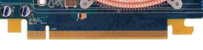
PCI Express interfaces on video cards


That's all for me, bye!
PCI Express is a bus that is used to connect a variety of components to a desktop PC. It is used to connect video cards, network cards, sound cards, WiFi modules and other similar devices. Intel began developing this bus in 2002. The PCI Special Interest Group, a non-profit organization, is currently developing new versions of this bus.
At the moment, the PCI Express bus has completely replaced such outdated buses as AGP, PCI and PCI-X. The PCI Express bus is located at the bottom of the motherboard in a horizontal position.
What is the difference between PCI Express and PCI
PCI Express is a bus that has been designed around the PCI bus. The main differences between PCI Express and PCI lie at the physical level. While PCI uses a common bus, PCI Express uses a star topology. Each PCI Express device is connected to a common switch with a separate connection.
The PCI Express software model follows the PCI model in many ways. Therefore, most of the existing CI controllers can be easily modified to use the PCI Express bus.
In addition, the PCI Express bus supports such new features as:
- Hot plugging devices;
- Guaranteed speed of data exchange;
- Energy consumption management;
- Control of the integrity of transmitted information;
How PCI Express works
The PCI Express bus uses a bi-directional serial connection to connect devices. Moreover, such a connection can have one (x1) or several (x2, x4, x8, x12, x16 and x32) separate lines. The more such lines are used, the higher the data transfer rate the PCI Express bus can provide. Depending on the number of lanes supported, the sizing on the motherboard will differ. There are slots with one (x1), four (x4) and sixteen (x16) lines.

Visual demonstration of PCI Express and PCI slot sizes
Moreover, any PCI Express device can work in any slot if the slot has the same or more lines. This allows a PCI Express card with an x1 slot to be installed in an x16 slot on the motherboard.
PCI Express bandwidth depends on the number of lanes and the bus version.
| One / both sides in Gbps | |||||||
| Number of lines | |||||||
| x1 | x2 | x4 | x8 | x12 | x16 | x32 | |
| PCIe 1.0 | 2/4 | 4/8 | 8/16 | 16/32 | 24/48 | 32/64 | 64/128 |
| PCIe 2.0 | 4/8 | 8/16 | 16/32 | 32/64 | 48/96 | 64/128 | 128/256 |
| PCIe 3.0 | 8/16 | 16/32 | 32/64 | 64/128 | 96/192 | 128/256 | 256/512 |
| PCIe 4.0 | 16/32 | 32/64 | 64/128 | 128/256 | 192/384 | 256/512 | 512/1024 |
If you need to choose a video card or, call us and we will help!
ISA bus
Bus interface standards
As the width of the bus increased and the clock frequency in the computer increased, the standards of the bus interface also changed. Currently, computers use the following main bus interface standards:
· ISA bus;
· PCI bus;
Other standards such as MCA (Micro Channel Architecture), EISA (Extended Industry Standard Architecture), and VESA, commonly referred to as local bus, VL bus and developed by the Video Electronics Standards Association (VESA) video electronics) are currently not used.
The first widespread bus interface standard, the ISA (Industry Standard Architecture) bus, was developed by IBM when they created the IBM PC AT (1984). This 16-bit bus clocked at 8.33 MHz can accommodate both 8-bit and 16-bit expansion cards (8.33 MB / s and 16.6 MB / s, respectively).
The exchange of data between high-speed external devices and RAM is performed with the participation of the processor, which in some cases can lead to a decrease in computer performance. In the direct access mode, introduced in the ISA bus, the peripheral device is connected to the main memory directly through DMA (Direct Memory Access) channels. This mode of data exchange is most effective in situations where a high speed is required to transfer a large amount of information (for example, when loading data into memory from a hard disk).
To organize direct memory access, a DMA controller built into one of the microcircuits on the motherboard is used. A device that requires direct memory access, through one of the free DMA channels, addresses the controller, telling it the path (address) from where or where to send data, the starting address of the data block and the amount of data. The exchange is initialized with the participation of the processor, but the actual data transfer is already under the control of the DMA controller, not the processor.
The ISA bus is absent in modern motherboards, and only in older computers.
The PCI (Peripheral Component Interconnect) bus was developed by Intel with a number of other companies in 1993 for its new high-performance Pentium processor.
All PCI standards are currently developed and maintained by the PCI-SIG (PCI - Special Interest Group) (PCI - Special Interest Group).
The latest PCI standard, PCI 3.0, adopted in 2004, defines both a 32-bit bus with a clock speed of 33 MHz and a peak bandwidth of 133 MB / s, and 64-bit buses with clock speeds of 33 and 66 MHz and a peak bandwidth, respectively. 266 and 533 MB / s.
To speed up data transfer in the PCI bus, burst mode is used. In this mode, data located at any address is transferred not one by one, but immediately as a whole set.
The underlying principle behind the PCI bus is the use of so-called bridges, which communicate between the PCI bus and other buses. An important feature of the PCI bus is that instead of DMA channels, it implements a more efficient bus mastering mode, which allows an external device to control the bus without the participation of the processor. During the transfer of information, the device supporting Bus Mastering seizes the bus and becomes the master. With this approach, the CPU is freed up to perform other tasks while the data is being transferred. This is especially important when using multitasking operating systems such as Windows and Unix.
The connectors for the PCI card on the motherboard are shown in Fig. ?????.
Figure: ?????. PCI card slots on motherboard:
a) 32-bit connector; b) 64-bit socket
PCI Hot Plug v1.0 is an addition to the PCI standard. PCI devices that comply with this standard can be plugged into or removed from the slot while the computer is running - a so-called hot plug.
PCI buses are used in modern computers to connect the internal devices of the system unit, such as a sound card or modem. However, for graphics devices, these buses have insufficient data transfer rates, so a new PCI-SIG standard was developed - PCI-X (X stands for eXtended) with clock speeds of 66, 133, 266 and 533 MHz and peak bandwidths, respectively, 533. 1066, 2132 and 4264 MB / s. This standard is backward compatible with PCI 3.0 standard, i.e. your computer can use both PCI 3.0 cards and PCI-X cards.
The latest version of the PCI-X standard, PCI-X 2.0, was adopted in 2002. Currently, the buses of this standard are practically not used, since in the same year PCI-SIG began developing a fundamentally new PCI bus standard - PCI Express.
PCI Express, also called PCI-E or PCe, replaces the parallel shared structure used by the PCI and PCI-X buses by daisy chaining devices using switches. The old name of this standard is 3GIO (3rd Generation Input / Output).
The last valid PCI Express standard is PCI Express Base 2.0, adopted in 2006.
Unlike the PCI standard, in which all devices are connected to a common 32-bit parallel unidirectional bus, PCI Express uses one or more bi-directional point-to-point serial connections, implemented over copper twisted pair, to connect the device.
When communicating over a twisted pair, the method of low-voltage differential signaling - LVDS (Low-Voltage Differential Signaling) is used. Data in LVDS is transmitted sequentially, bit by bit. In this case, a differential pair is used to transmit one signal, i.e. that the transmitting side applies different voltage levels to the conductors of the pair, which are compared on the receiving side. To encode information, the voltage difference across the conductors of the pair is used. The small amplitude of the signal, as well as the insignificant electromagnetic influence of the wires of the pair on each other, allows to reduce noise in the line and transmit data at high frequencies, i.e. with high speed. To increase the data transfer rate, several connections (twisted pairs) can be used, over which the bits are transmitted in parallel, i.e. at the same time.
PCI Express can use one or more connections to transfer data. The number of connections for a device is specified using a number followed (or preceded by) the letter x. The specification currently defines the connections 1x, 2x, 4x, 8x, 16x and 32x. Each of these PCI Express bus connections (with the exception of the 32x connection, which is not used yet) has its own type of connector. In fig. ???? the most common PCI Express slots are shown: 1x, 2x, 4x, 8x and 16x.

Figure: ?????. The most common PCI Express slots: a) 1x slot; b) 4x slot;
c) 8x slot; d) 16x slot;
The throughput in the PCI Express bus per one connection is currently 2.5 Gb / s with the prospect of increasing to 10 Gb / s. PCI Express is intended to replace PCI and PCI-X, as well as the AGP standard discussed in the next section. However, the PCI Express standard is compatible with these standards and, apparently, will be used together with them for a long time, since at present and continues to be issued many cards according to the PCI and AGP standards.
When changing only one video card, be sure to keep in mind that new models may simply not fit your motherboard, since there are not just several different types of expansion slots, but also several different versions of them (as applied to both AGP and PCI Express). If you are unsure of your knowledge of this topic, please read the section carefully.
As we have already noted above, the video card is inserted into a special expansion slot on the computer's motherboard, through this slot the video chip exchanges information with the central processor of the system. Motherboards often have one or two different types of expansion slots, differing in bandwidth, power settings, and other characteristics, and not all of them are suitable for installing video cards. It is important to know the connectors available in the system and buy only the video card that matches them. Different expansion connectors are physically and logically incompatible, and a video card designed for one type will not fit into another and will not work.
Fortunately, not only ISA and VESA Local Bus expansion slots (which are of interest only to future archaeologists) and their corresponding video cards have fallen into oblivion over the past time, but video cards for PCI slots have also practically disappeared, and all AGP models are hopelessly outdated. And all modern GPUs use only one type of interface - PCI Express. Previously, the AGP standard was widespread, these interfaces differ significantly from each other, including the bandwidth, the capabilities provided for powering the video card, as well as other less important characteristics.
Only a very small part of modern motherboards do not have PCI Express slots, and if your system is so old that it uses an AGP video card, then you will not be able to upgrade it - you need to change the entire system. Let's take a closer look at these interfaces; these are the slots you need to look for on your motherboards. See photos and compare.

AGP (Accelerated Graphics Port or Advanced Graphics Port) is a high-speed interface based on the PCI specification, but designed specifically for connecting video cards and motherboards. Although the AGP bus is better suited for video adapters compared to PCI (not Express!), It provides a direct connection between the central processor and the video chip, as well as some other features that increase performance in some cases, for example, GART - the ability to read textures directly from RAM without copying them into video memory; higher clock frequency, simplified data transfer protocols, etc., but this type of slots is hopelessly outdated and new products with it have not been released for a long time.
But still, for the sake of order, we will also mention this type. AGP specifications appeared in 1997, then Intel released the first version of the description, which included two speeds: 1x and 2x. AGP 4x appeared in the second version (2.0), and 8x appeared in 3.0. Let's consider all the options in more detail:
AGP 1x is a 32-bit channel running at 66 MHz, with a bandwidth of 266 MB / s, which is twice the PCI bandwidth (133 MB / s, 33 MHz and 32 bits).
AGP 2x is a 32-bit channel operating with a doubled bandwidth of 533 MB / s at the same frequency of 66 MHz due to data transfer along two edges, similar to DDR memory (only for the direction "to the video card").
AGP 4x is the same 32-bit channel operating at 66 MHz, but as a result of further tweaks, a quadruple "effective" frequency of 266 MHz was achieved, with a maximum bandwidth of more than 1 GB / s.
AGP 8x - additional changes in this modification made it possible to get the bandwidth up to 2.1 GB / s.
AGP video cards and corresponding slots on motherboards are compatible within certain limits. Graphics cards rated for 1.5V do not work in 3.3V slots and vice versa. However, there are also universal connectors that support both types of boards. Video cards designed for a morally and physically outdated AGP slot have not been considered for a long time, so to learn about old AGP systems, it would be better to read the article:

PCI Express (PCIe or PCI-E, not to be confused with PCI-X), formerly known as Arapahoe or 3GIO, differs from PCI and AGP in that it is a serial rather than a parallel interface, which reduces the number of pins and increases the bandwidth. PCIe is just one example of the shift from parallel to serial buses, other examples of this movement are HyperTransport, Serial ATA, USB and FireWire. An important advantage of PCI Express is that it allows multiple single lanes to be stacked into a single lane to increase bandwidth. The multichannel sequential design increases flexibility, slower devices can be assigned fewer lines with fewer pins, and faster ones more.
PCIe 1.0 transfers data at 250 MB / s per lane, nearly double the capacity of conventional PCI slots. The maximum number of lanes supported by PCI Express 1.0 slots is 32, which gives a bandwidth of up to 8 GB / s. And the PCIe slot with eight working lanes is roughly comparable in this parameter with the fastest AGP version - 8x. Which is even more impressive when you consider the possibility of simultaneous transmission in both directions at high speed. The most common PCI Express x1 slots provide throughput of one lane (250 MB / s) in each direction, and PCI Express x16, which is used for video cards and which combines 16 lanes, provides bandwidth up to 4 GB / s in each direction.
Despite the fact that the connection between two PCIe devices is sometimes assembled from several lines, all devices support a single line, at least, but can optionally work with a large number of them. Physically, PCIe expansion cards go in and work fine in any slots with equal or more lanes, so a PCI Express x1 card will work fine in x4 and x16 slots. Also, a physically larger slot can work with a logically fewer lines (for example, a seemingly ordinary x16 connector, but only 8 lines are routed). In any of the above options, PCIe will choose the highest possible mode and will work fine.
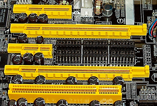
Most often, x16 connectors are used for video adapters, but there are boards with x1 connectors. And most motherboards with two PCI Express x16 slots operate in x8 mode to create SLI and CrossFire systems. Physically, other slot options such as x4 are not used for video cards. Let me remind you that all this applies only to the physical layer, there are also motherboards with physical PCI-E x16 slots, but in reality with 8, 4 or even 1 channels. And any video cards designed for 16 channels will work in such slots, but with lower performance. By the way, the photo above shows the x16, x4 and x1 slots, and for comparison, PCI is also left (below).
Although the difference in games is not that big. For example, here is a review of two motherboards on our website, which examines the difference in the speed of 3D games on two motherboards, a pair of test video cards in which operate in 8-channel and 1-channel modes, respectively:
The comparison that interests us is at the end of the article, pay attention to the last two tables. As you can see, the difference at medium settings is quite small, but in heavy modes it starts to increase, and a big difference was noted in the case of a less powerful video card. Take note of this.
PCI Express features not only bandwidth, but also new power consumption capabilities. This need arose because the AGP 8x slot (version 3.0) can only transfer no more than 40-plus watts in total, which was no longer enough for video cards of the then generations designed for AGP, on which one or two standard four-pin power connectors were installed. The PCI Express slot can carry up to 75W, and the additional 75W is received over the standard six-pin power connector (see the last section of this part). Recently, video cards with two such connectors have appeared, which in total gives up to 225 watts.
Subsequently, the PCI-SIG group, which develops the corresponding standards, presented the main PCI Express 2.0 specifications. The second version of PCIe doubles the standard bandwidth, from 2.5 Gbps to 5 Gbps, so the x16 connector can transfer data at speeds up to 8 GB / s in each direction. At the same time, PCIe 2.0 is compatible with PCIe 1.1, old expansion cards usually work fine in new motherboards.
The PCIe 2.0 specification supports both 2.5 Gb / s and 5 Gb / s transfer rates to ensure backward compatibility with existing PCIe 1.0 and 1.1 solutions. PCI Express 2.0 backward compatibility allows legacy 2.5 Gb / s solutions in 5.0 Gb / s slots, which will simply operate at a lower speed. And devices designed to version 2.0 specifications can support speeds of 2.5 Gbps and / or 5 Gbps.
Although the main innovation in PCI Express 2.0 is the speed doubled to 5 Gbps, this is not the only change, there are other modifications to increase flexibility, new mechanisms for programmatically controlling the connection speed, etc. We are most interested in the changes related to with power supply of devices, since the power requirements of video cards are steadily growing. PCI-SIG has developed a new specification to accommodate the increasing power consumption of graphics cards, expanding the current power supply capabilities to 225/300 watts per graphics card. To support this specification, a new 2 × 4-pin power connector is used to provide power to top-end graphics cards.
Video cards and motherboards with PCI Express 2.0 support appeared on the market already in 2007, and now there are no others on the market. Both major video chip manufacturers, AMD and NVIDIA, have released new GPU and video card lines that support the increased bandwidth of the second version of PCI Express and take advantage of new power supply options for expansion cards. All of them are backward compatible with motherboards with PCI Express 1.x slots, although incompatibility is observed in some rare cases, so you need to be careful.
Actually, the appearance of the third version of PCIe was an obvious event. In November 2010, the specifications for the third version of PCI Express were finally approved. Although this interface has a transfer rate of 8 Gt / s instead of 5 Gt / s in version 2.0, its bandwidth has doubled again compared to the PCI Express 2.0 standard. To do this, we used a different encoding scheme for data sent over the bus, but at the same time, compatibility with previous PCI Express versions was preserved. The first products of the PCI Express 3.0 version were presented in the summer of 2011, and real devices have just begun to appear on the market.
A war broke out among motherboard manufacturers for the right to be the first to present a product with support for PCI Express 3.0 (mainly based on the Intel Z68 chipset), and several companies presented the corresponding press releases at once. Although at the time of the update of the guide, there are simply no video cards with such support, so it's just not interesting. By the time PCIe 3.0 support is needed, completely different boards will appear. Most likely, this will not happen until 2012.
By the way, we can assume that PCI Express 4.0 will be presented over the next few years, and the new version will also have twice the bandwidth demanded by that time. But this will not happen very soon, and we are not interested yet.
External PCI Express
In 2007, the PCI-SIG group, which is officially standardizing PCI Express solutions, announced the adoption of the PCI Express External Cabling 1.0 specification, which describes the standard for data transfer over the external PCI Express 1.1 interface. This version allows data transfer at a speed of 2.5 Gb / s, and the next one should increase the bandwidth to 5 Gb / s. The standard provides four external slots: PCI Express x1, x4, x8 and x16. Older connectors are equipped with a special tongue to facilitate connection.

The external version of the PCI Express interface can be used not only for connecting external video cards, but also for external drives and other expansion cards. The maximum recommended cable length is 10 meters, but it can be increased by connecting the cables through a repeater.
In theory, this could make life easier for laptop enthusiasts when running on battery power using a low-power integrated video core, and when connected to a desktop monitor, a powerful external video card. The upgrade of such video cards is greatly facilitated, there is no need to open the PC case. Manufacturers can make completely new cooling systems that are not limited by the features of expansion cards, and there should be fewer problems with power supply - most likely, external power supplies designed specifically for a specific video card will be used, they can be built into one external case with a video card using one cooling system. It may be easier to assemble systems on several video cards (SLI / CrossFire), and given the constant growth in the popularity of mobile solutions, such external PCI Express should have gained a certain popularity.
They should have, but they didn't. As of autumn 2011, there are practically no external versions of video cards on the market. Their circle is limited to outdated models of video chips and a narrow selection of compatible laptops. Unfortunately, the business of external video cards did not go any further, and slowly died out. Even victorious advertising announcements from notebook manufacturers are no longer heard ... Perhaps, the capacities of modern mobile video cards simply began to suffice even for demanding 3D applications, including many games.
There remains hope for the development of external solutions in the promising interface for connecting Thunderbolt peripherals, formerly known as Light Peak. It was developed by Intel Corporation based on DisplayPort technology, and the first solutions have already been released by Apple. Thunderbolt combines DisplayPort and PCI Express capabilities and allows you to connect external devices. However, so far those simply do not exist, although the cables already exist:

In this article, we do not touch outdated interfaces, the vast majority of modern video cards are designed for the PCI Express 2.0 interface, therefore, when choosing a video card, we suggest considering only this interface, all data on AGP are given for reference only. The new boards use PCI Express 2.0 interface, combining the speed of 16 PCI Express lanes, which gives the bandwidth up to 8 GB / s in each direction, which is several times more than the best AGP. In addition, PCI Express operates at this speed in each direction, unlike AGP.
On the other hand, products with PCI-E 3.0 support have not really come out yet, so it doesn't make much sense to consider them either. If we are talking about upgrading an old or buying a new board, or changing the system and video cards at the same time, then you just need to purchase boards with the PCI Express 2.0 interface, which will be quite sufficient and most widespread for several more years, especially since products of different PCI Express versions are compatible with each other ...


