After reading this post and the accompanying discussion, I decided to try to clarify what USB Power Delivery is and how it actually works. Unfortunately, I got the impression that most of the participants in the discussion take 100 watts over USB too literally, and do not fully understand what is behind it at the level of schematics and protocols.
So, briefly - the main points:
- USB PD defines 5 standard power profiles - up to [email protected]A, before [email protected]A, before [email protected]A, before [email protected]A and before [email protected]A
- Power Delivery cables and ports are certified and have additional pins in the connector
- The type of cable and its compliance with the profile are determined automatically through additional pins and the definition of the type of USB connector (micro, standard, A, B, etc.)
- Regular USB cables (not Power Delivery) are certified only for the first profile before [email protected]
- When connected, roles are assigned, between the one who gives the current ( Source) and who consumes ( Sink / Receiver)
- Source and Receiver exchange messages using a special protocol that works in parallel with the traditional USB
- The protocol uses the VBus / GND pair as a physical medium. This is why Power Delivery is independent of the underlying USB protocol and is backward compatible with USB 2.0 and 3.0.
- Using messages, the source and receiver can change roles at any time, change the current and / or voltage, go into hibernation or wake up, etc.
- Devices can optionally support PD control via traditional USB requests, descriptors, etc.
About males About cables
USB Power Delivery works with six types of connectors:Accordingly, the following types of connections are allowed in pairs
- USB 3.0 PD Standard-A<-> USB 3.0 PD Standard-B plug
- USB 3.0 PD Standard-A<-> USB 3.0 PD Micro-B plug
- USB 3.0 PD Micro-A<-> USB 3.0 PD Micro-B plug
- USB 3.0 PD Micro-A<-> USB 3.0 PD Standard-B plug
- USB 2.0 PD Standard-A<-> USB 2.0 PD Standard-B plug
- USB 2.0 PD Standard-A<-> USB 2.0 PD Micro-B plug
- USB 2.0 PD Micro-A<-> USB 2.0 PD Micro-B plug
- USB 2.0 PD Micro-A<-> USB 2.0 PD Standard-B plug
About ports
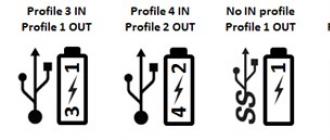
After certification, USB PD ports are labeled as follows:
This logo informs about the USB version (2.0 or 3.0 SuperSpeed), as well as the power supply profiles that this port supports. The "I" value means the consumed profile required for the full functioning of the device, and the "O" value means which profile the port can provide. Examples of port markings:
- The first port supports USB2. He can feed according to Profile 1 ( [email protected]) and uses Profile 3 ( [email protected] or [email protected]) for full functioning. For example a port for a tablet or netbook.
- The second port supports USB2. He can supply food according to Profile 2 ( [email protected] or [email protected]) and uses Profile 4 ( [email protected] or [email protected] or [email protected]) for full functioning. For example, a port for a laptop or laptop.
- The third port supports USB3. It only feeds on Profile 1 ( [email protected]). He himself is not powered by VBus. For example, a port of a desktop, monitor, TV, etc.
- The fourth port supports USB3. As in the first example, it can supply power according to Profile 1 ( [email protected]) and itself requires power according to Profile 3 for full functioning ( [email protected] or [email protected]). Think of an example yourself :)
Physical channel
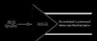
USB PD defines the schematic diagram of the physical organization of a cable connection as follows:
As can be seen from the diagram, USB PD also requires that both the source and the receiver implement voltage drop / surge detection circuits, as well as methods for determining a discharged battery for cases when one of the parties cannot be powered from its internal source.
The following are suggested as algorithms for determining a discharged battery. If one of the sides puts a resistance of 1kΩ between the screen and the ground, this indicates that its battery is discharged. In such a situation, the other side takes on the role of a source and begins to give the minimum 5V to give power to the opposite side through VBus and start exchanging messages using the USB PD protocol.
As mentioned earlier, the USB PD protocol uses the VBus line to exchange messages. Below is a block diagram defining the key functional elements of the transmitter:

And, accordingly, the same block diagram for the receiver:

Serialized 4b5b encoding and 5b4b decoding mean that all data on the bus, except for the packet preamble, is transmitted in five-bit sequences in accordance with the encoding table defined by the standard. Each such sequence encodes either one of 16 digits (0x00..0x0F), or start / sync / reset and end of packet signals. Thus, the transfer of one byte takes 10 bits, a 16-bit word - 20 bits and a 32-bit double word - 40 bits, etc.
Logical channel
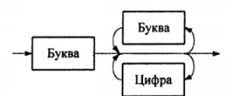
The USB PD protocol is based on serial challenge-response pairs. Requests and responses are sent using packets. Packets consist of a preamble (preparatory phase), a start of an SOP packet (three Sync-1 signals and a final Sync-2 encoded in 4b5b), a header, 0..N payload bytes, a checksum (CRC-32) and an end signal packet (single EOP signal):
As mentioned above, the preamble is not encoded in 4b5b. SOP, CRC and EOP are coded 4b5b at the physical layer, the header and payload are coded at the logical protocol layer.
The bus is reset by sending three RST1 signals and a terminating RST2 signal, according to the 4b5b coding.
Protocol
All USB PD messages consist of a header and a data chunk of arbitrary length. Messages are either generated at the logical protocol layer and then forwarded to the physical layer, or received at the physical layer and then forwarded to the logical protocol layer.The message header has a fixed length of 16 bits and consists of the following fields: 
There are two types of messages - control and informational (data).
Control messages
The control messages consist only of a header and a CRC. The number of data objects for such messages is always set to 0. The types of USB PD control messages are shown in the table below:
Separately, it should be mentioned that fields of the form tSourceActivity, tSinkRequest etc. are constants whose values \u200b\u200bare globally set by the specification itself in a separate chapter. This was done because they were determined empirically as a result of prototyping, and the found optimal values \u200b\u200bwere simply substituted in a separate chapter so as not to scour the entire specification.
Information messages
This type of messages is intended to receive detailed information about the source or receiver, as well as to transmit the requested characteristics of the power supply - current strength, voltage, etc. Data messages always contain a nonzero value in the "Number of Data Objects" field.The specification defines four types of information messages:
- Power Data Object (PDO) - used to describe source port characteristics or sink requirements
- Request Data Object (RDO) - used by the receiver port to set the power supply agreement
- BIST (Built In Self Test) Data Object (BDO) - used to test the connection against the specification for the physical connection
- Vendor Data Object (VDO) - used to transfer non-standard, additional or other proprietary information determined by the equipment manufacturer and outside the scope of the USB PD specification.

Performance message
The source port is always required to communicate its characteristics to the receiver by transmitting a series of 32-bit PDOs. The information transmitted through these objects is used to determine the capabilities of the source, including the ability to operate in receiver mode.Performance messages are represented as one or more objects following the title:
Performance messages are transmitted:
- From source to receiver at a certain time interval, with direct cable connection. The source must continue to send messages for one minute after connecting until a successful power agreement is established or the receiver returns an RDO with the Capability Mismatch flag.
- From source to sink for the purpose of forcibly resetting the power agreement or changing characteristics.
- In response to control messages Get_Source_Capor Get_Sink_Cap
The PDO corresponding to a 5V constant type element must always go first in the object chain.
PDO Object Structure: 
Different characteristics are offered for each type of power supply.
Constanttype of power supply, constant voltage. The source must have at least one such element: 
Programmabletype of power supply, voltage can be regulated by requests within the range between minimum and maximum: 
Variativetype of power supply, the voltage can vary within the specified limits of the absolute minimum and absolute maximum, but cannot be regulated: 
Battery, this type is used to indicate batteries that can be directly connected to the VBus line: 
Request message
Request messages are sent by the receiver to the source to communicate its requests during the power agreement establishment phase. This message is sent in response to a performance message and MUST contain one and only one data request object, RDO, which describes the required power rating information for the receiver.This request is of two types, depending on the addressable power supply type conveyed in the source characteristics message. For requests to a constant or variable type power supply unit, or a battery, the fields "Operating Current / Power" and "Total Current / Prog Voltage" are interpreted in one way, and for requests to a programmable type element - in another way, since in this case the voltage is also requested , and current strength.
RDO object structure: 
In my opinion, this information is enough to get a good understanding of how USB Power Delivery works. I deliberately did not delve into the jungle associated with timers, counters and error handling.
Interaction with traditional USB
As mentioned above, Power Delivery is a standalone subsystem that operates in parallel and independent of Canonical USB. However, in cases where devices implement both USB and Power Delivery protocols, the specification recommends implementing the so-called. System Policy Manager or SPM, a component that can control USB PD equipment through traditional USB requests.
For systems with SPM support, the specification recommends providing PD information through special types of USB descriptors. I do not consider it necessary to delve into them in detail, I will just list their names:
- Power Delivery Capability Descriptor, is part of the BOS descriptor and reports whether the device supports USB battery charging, whether it supports the USB PD standard, whether it can act as a power source, and whether it can be a receiver. In addition, this descriptor contains information about the number of source ports, receiver ports and the version of the supported USB Battery Charging and Power Delivery specifications.
- Battery Info Capability Descriptor, is required for all devices claiming a battery as one of the power supply elements. Contains information about the name, serial number and manufacturer of the battery, its capacity, as well as the current thresholds in charged and discharged state.
- PD Consumer Port Capability Descriptor, is required for all devices that have declared support for at least one receiver port. Contains information on support for Power Delivery and Battery Charging standards, minimum and maximum voltage, operating power, maximum peak power and maximum time it can consume this peak power
- PD Provider Port Capability Descriptor, is required for all devices that have declared support for at least one power supply port. Contains information about support for Power Delivery and Battery Charging standards, as well as a list of all PDO objects that characterize the power supply elements available to the device.
- PD Power Requirement Descriptor, required for all USB PD compatible receiver devices. Every device must return at least one such descriptor as part of its configuration descriptor. This descriptor must come immediately after the first interface descriptor. If there are several of them, it must go after every first function interface descriptor if IAD is used, or in the case of a composite device without IAD, immediately after each interface descriptor, and before the endpoint descriptors.

Conclusion
I hope that with this post I have fueled public interest in USB Power Delivery. I will humbly note that the author is directly related to this specification, so he is ready to answer any questions about Power Delivery in particular and USB in general.Interface USB (Universal Serial Bus - Universal Serial Interface) is designed to connect peripheral devices to a personal computer. Allows you to exchange information with peripheral devices at three speeds (specification USB 2.0):
- Low speed ( Low Speed - LS) - 1.5 Mbit / s;
- Full speed ( Full Speed - FS) - 12 Mbps;
- High speed ( High speed - HS) - 480 Mbps.
USB interface connects host (host) and device. The host is located inside the personal computer and controls the operation of the entire interface. In order to connect more than one device to one USB port, apply hubs (hub - a device that provides connection to the interface of other devices). Root hub (root hub) resides inside the computer and is connected directly to the host. The USB interface uses a special term "function" is a logically complete device that performs a specific function. The USB interface topology is a set of 7 layers ( tier): the first level contains the host and root hub, and the last one contains only functions. A device that includes a hub and one or more functions is called composite (compaund device).
A hub or feature port that connects to a higher-level hub is called an upstream port ( upstream port), and a hub port that connects to a lower-level hub or function is called a downstream port ( downstream port).
All data transfers on the interface are initiated by the host. Data is transmitted as packets. The USB interface uses several types of packages:
- tag package (token paket) describes the type and direction of data transfer, the device address and the serial number of the endpoint (CT is the addressable part of the USB device); package tags are of several types: IN, OUT, SOF, SETUP;
- data packet (data packet) contains the transmitted data;
- approval package (handshake packet) is intended for reporting the results of data transfer; there are several types of rebate packages: ACK, NAK, STALL.
The USB interface uses several types of information transfers.
- Control forwarding (control transfer) is used for device configuration as well as for other device-specific purposes.
- Streaming (bulk transfer) is used to transmit a relatively large amount of information.
- Interrupt forwarding (iterrupt transfer) is used to transmit a relatively small amount of information, for which timely transmission is important. Has a limited duration and increased priority relative to other types of transfers.
- Isochronous forwarding (isochronous transfer) is also called real-time streaming. The information transmitted in such a transfer requires real time scale in its creation, transmission and reception.
Streaming transfers
characterized by guaranteed error-free data transmission between the host and the function by detecting transmission errors and re-requesting information.
When the host becomes ready to receive data from the function, it sends the function in the phase of transmission of the flag packet. IN-package. In response to this, the function, in the data transfer phase, sends a packet with data to the host or, if it cannot do this, sends NAK- or STALL-package. NAK- the package informs about the temporary unavailability of the function to transmit data, and STALL-package informs about the need for host intervention. If the host successfully received the data, then it sends functions in the negotiation phase ACK
When the host becomes ready to transmit data, it sends functions OUT-package followed by a data package. If the function successfully received the data, it sends to the host ACK-package, otherwise sent NAK-or STALL-package.
Control transfers
contain at least two stages: Setup stage and status stage... Between them can also be located data transfer stage. Setup stage used to perform SETUP transactions, during which information is sent to the control CT function. SETUP transaction contains SETUP-package ,
data package and reconciliation package. If the data packet is successfully received by the function, then it sends to the host ACK-package. Otherwise, the transaction ends.
IN data transfer stages control transfers contain one or more IN- or OUT-transactions, the transmission principle of which is the same as in streaming transfers. All transactions at the stage of data transfer must be made in the same direction.
IN status stage the last transaction is made, which uses the same principles as in streaming. The direction of this transaction is opposite to that used in the data transfer stage. The status stage is used to report the result of the SETUP stage and the data transfer stage. Status information is always passed from function to host. When control record (Control write transfer) status information is transmitted in the data transfer phase of the status stage of the transaction. When control reading (Control Read Transfer) the status information is returned in the negotiation phase of the status stage of the transaction, after the host has sent a data packet of zero length in the previous phase of data transfer.
Interrupt transfers
may contain IN- or OUT- forwarding. Upon receipt IN-package function can return a data packet, NAK-package or STALL-package. If the function does not have information for which an interrupt is required, then in the data transfer phase, the function returns NAK-package. If the operation of CT with interruption is suspended, then the function returns STALL-package. If interruption is necessary, the function returns the necessary information in the data transfer phase. If the host has successfully received the data, then it sends ACK-package. Otherwise, no matching packet is sent by the host.
Isochronous transactions
contain transmission phase and data transfer phasebut don't have negotiation phase... Host sends IN- or OUT-sign, after which, in the CT data transfer phase (for IN-sign) or host (for OUT-sign) sends data. Isochronous transactions do not support the reconcile phase and re-send data in case of errors.
Due to the fact that the USB interface implements a complex information exchange protocol, a microprocessor unit is needed in the USB interface device to support the protocol. Therefore, the main option when developing an interface device is to use a microcontroller that will support the exchange protocol. Currently, all major microcontroller manufacturers produce products that include a USB block.
|
Connector USB type A most common and most recognizable. Computer mice, keyboards, external hard drives are equipped with exactly this connector. The development of this USB form factor was completed in the 90s of the last century, the release took place along with the first version of the standard. The main advantage is strength and reliability, allowing it to withstand a large number of connections without any problems. Despite the rectangular shape of the connector, it cannot be inserted incorrectly thanks to the special protection. However, due to the large dimensions that were not suitable for portable devices, smaller USB connectors were developed.
Connectors USB typeB usually used to connect peripherals to a computer on the device side. Now this type of connector is not common. There are also portable type B connectors - MiniUSB andMicroUSB.
The emergence of Mini USB was due to the widespread use of miniature devices, the size of which did not allow the use of full-fledged connectors. However, it soon became clear that this connector was not reliable. Therefore, it was replaced by the Micro USB specification. The modified shape allowed for a firm hold in the device, besides, the connector was even smaller than the Mini USB. The use of Micro USB has become the de facto standard for all compact devices. But now it is being replaced by USB type C.
USBType-C or USB-C is the last available USB connector standard. The specification was released in 2014. This version provides high speed data transfer as well as two-way connectivity.
USB standards
On January 15, 1996, the first specification of the universal serial bus standard was introduced - USB 1.0... The data transfer rate did not exceed 12 Mbps, and the maximum current supplied to the connected devices was 500 mA.
VersionUSB 1.1 only corrected mistakes made in the design of the first specification, but it was 1.1 that was first widely used. The USB 2.0 standard was announced in April 2000 and served as an update to USB 1.1.
USB 2.0 provided additional bandwidth for applications, media and storage. The data transfer speed has increased 40 (!) Times. To ensure a smooth transition to the new standard for both consumers and manufacturers, USB 2.0 was fully compatible with original USB devices.
This standard supports three speed modes (1.5, 12 and 480 megabits per second):
- Low Speed \u200b\u200b(no more than 1.5 Mbit / s) - keyboards, mice, joysticks;
- Full Speed \u200b\u200b(no more than 12 Mbit / s) - audio and video devices;
- High Speed \u200b\u200b(no more than 480 Mbit / s) - high-performance peripherals;
The introduction of USB 2.0 has made significant progress in the development of peripheral "devices" for personal computers. This standard allowed several power-hungry devices to be connected to the host at the same time.
Standard USB 3.0 (SuperSpeedUSB) became official on November 17, 2008. The new specification supported transfer rates 10 times faster (up to 4.8 gigabits per second) than USB 2.0. The maximum current supplied to peripheral devices has increased from 500 to 900 mA. This allowed not to use additional power supplies for some gadgets, and also to increase the number of devices powered by one port.
The transition to USB 3.0 has been very slow. Intel has postponed implementation of the standard to its chipsets until 2011. The software also lacked support for the new specification: neither Windows nor Linux could work with version 3.0 at that time.
In the summer of 2013, an updated standard was developed - USB 3.1... The data transfer rate has increased to 10 Gbps. The 3.1 standard is backward compatible with versions 2.0 and 3.0. It was with this version that new USB Type-C connectors began to appear.
USB 3.2 promises to double the data transfer rate again - up to 20 Gbps.
USB hubs (USB hubs, USB hubs)
Computers have at least one or two USB ports. But with so many USB devices on the market, you will quickly run out of available ports. You can have a keyboard, mouse, printer, microphone and webcam connected via USB at the same time. An obvious question arises: "How to connect all devices?"
An easy solution to the problem is to buy an inexpensive USB hub (hub). What is a USB hub?
USB hub is a device that acts as an "adapter" from one USB connector to more.
The USB standard supports connecting up to 127 devices to one port, and USB hubs are part of the standard. In addition, using USB hubs, you can increase the length of the USB cable from the maximum possible 5 meters for one cable to 30.
You plug a splitter into your computer and then plug your devices (or other splitters) directly into it. By connecting hubs together, you can create dozens of available USB ports on one computer.
Hubs may or may not power connected devices. Power-hungry devices (printers, scanners, etc.) have their own power source, but low-power devices (mice, keyboards, etc.) get their power from the computer. This greatly simplifies the work with them. Power (up to 500 milliamps at 5 volts for USB 2.0 and 900 milliamps for USB 3.0) comes from the computer's bus. If you have many self-powered devices (such as printers and scanners), then your hub does not need power. If you have a lot of non-powered devices such as mice and keyboards, you probably need a powerful hub with its own power supply.
How does USB work?
As we already said, several devices can be connected to one USB host at the same time. Each device is assigned a unique the address - 7-bit binary number (hence the limit of 127 devices). At the moment of connecting to the host, the device sends data containing information about the device type, manufacturer, etc. Based on this data, the host decides in which mode to work with this machine.
Data exchange between devices is carried out using transactions- sequences consisting of several packets (blocks) of information. The exchange always begins with sending a small packet (token) from the host, which contains information about the device address, direction of transmission, and so on. In order not to go too deep, we will give an example of the most commonly used tokens:
- IN (the host is ready to receive data from the device);
- OUT (the host is ready to transmit data to the device);
- SETUP (the host informs the device about the subsequent transfer of configuration information);
One transaction can transmit several packets at once, provided that the length of the data in the packet is the maximum allowed. Data transmission ends when an incomplete data packet is received. After that, the device sends back a confirmation packet about the success or failure of the operation. Packets in a transaction are transmitted continuously and without pauses, the delay should not exceed 1 microsecond. If the pause is extended, then the transaction will be considered false.
The use of USB ports and connectors has become ubiquitous. They apply to computers, mobile devices, and storage devices. USB connectors have greatly facilitated the process of powering devices and transferring data in the modern world.
Today, user PC knows that it is possible to connect your systems to a wide range of external devices: not only printers and modems, but also scanners, camcorders, portable storage devices, PDAs and many other peripherals. But for a long time, anyone who tried to do this was hampered by the lack of suitable I / O ports.
In our age of innovative technologies, no person can imagine their life without a computer. But what if you have problems with it? Not always, even the most advanced user, is able to cope alone in computer problems. Therefore, our computer help Perovo offers its services with a trip to anywhere in Perovo, computer repair for you, wherever you are
For a long time the only universal pC interface was SCSI, an expensive option justified only for high-bandwidth devices. Peripherals generally require either a serial or parallel port, or use a proprietary interface.
Originally designed for printers and modems, the computer's serial and parallel ports leave much to be desired as general interface targets. Their data transfer rates are low (maximum 115Kbit / sec for the serial port, up to 400KB / sec for the parallel interface), and each device requires its own hardware interrupt (IRQ), which limits the number of possible extensions. And there was no hope of achieving connectivity and operation with these interfaces, this is essential if connecting peripheral devices to PC must be done in a way that can be achieved by non-technical users.
The need for medium speeds, an inexpensive interface that can be used to connect an almost unlimited number of devices was eventually recognized and a solution was found. Universal Serial Bus - USB.
Goal design
USB was designed to allow a large number (up to 127) low and medium speed peripherals to be installed on a PC, with a maximum transfer rate of 12Mbit / sec. USB was never intended as an alternative to the SCSI port, but it is still much faster than serial or parallel ports.
Particular attention has been paid to the needs of audio and video devices, for which more importance has been placed on performance for the next generation of personal applications. The USB design provides isochronous data that will be delivered without delays and which can negatively affect the image and speech quality.
USB interface was designed to be easy to plug and play. Devices can be added and removed even while the system is running, avoiding the need to reboot the system and reconfigure it. Technical issues such as assigning an identifier to a device that take care of the hardware and software architecture so that these common sources will not be a problem and a configuration error. A power-saving system was introduced, allowing devices to be suspended.
Typical devices USB requiring low to medium bandwidth. At the low end of the bandwidth, USB can be used to connect keyboard and mouse to computer. On the top, scanners, backup devices or cameras for video conferencing applications that can use USBeliminating the need for proprietary interface boards and associated installation and setup problems.
A bus architecture in which data for different devices travels over the same cable also has the potential to simplify communications. For example, a mouse can connect to a keyboard, and a single cable will then link them to PC... Although monitors still require an analog VGA cable, a separate USB link will allow the monitors to run from software on PC, not on the screen. In the case of a multimedia monitor, audio data for the built-in speakers and microphone can also be sent over the same cable.
Physical layer
USB devices are connected together using an inexpensive 90 ohm white four-conductor cable. USB devices can be either self-powered (with its own self-powered) or bus-powered. One of the pairs of wires in the cable USB used to transmit power + 5: pin 1 carries the +5 V supply voltage, pin 4 is common. There are two classes of bus powered device. Low-power devices can consume no more than 100 mA of current, while high-power devices can consume up to 500 mA. The second pair of wires, D + and D-on pins two and three, is a twisted pair used for data transmission. These wires use differential signaling: and carry a signal with respect to ground, a transition occurs when two data lines are from reverse polarity with respect to each other. This gives better noise immunity than a conventional single-ended logic signal.
The data is sent as a synchronous serial bit stream, encoded with NRZI (0 represents the signal transition and 1 in the transition period.) The bit is used to ensure that transitions occur frequently enough so that receivers do not lose synchronization. Temporal signals are transmitted with the data, the field synchronization precedes each data packet.
USB works at two different speeds. Full speed gives a bandwidth of 12Mbit / sec. At this speed, a shielded cable must be used to obtain adequate immunity to interference and prevent electromagnetic interference (EMI). Shielded cable approx. 5 mm. in diameter, cable segments can have a maximum length of 5 meters.
For applications that require low bandwidth, there is a lower operating speed. This allows a slightly thinner and cheaper unshielded cable to be used. The cable length is reduced with an unshielded cable and can be maximum 3m. To prevent the signal, the high speed is transmitted over an unshielded cable (which will result in EMI) and to avoid the risk of low bit rate devices misdetecting the full baud rate in the form of commands they must respond, the low speed device communications are disabled at that time when full speed signaling is used.
Two types of plug and socket, known as A series and B series, which are specified for USB ports. The plug and socket series are designed for use with devices to which an external cable is firmly attached, such as keyboards, mice, and hubs. Series B connectors are used when the cable is USB removable, as in the case of printers, scanners and modems. The two types are not interchangeable.
The B series has 10.6mm x 12.0mm male connectors. Both plugs and sockets are small, so the ports USB installed on laptops as well as desktop PCas the technology becomes more common. USB ports the graphic icon shown in the figure is assigned.
The continuation of the article follows, we read in the following articles.
Let's start with a minimum:include 18f2455 - library for the used MK
--
enable_digital_io () - switching all inputs to digital mode
--
aliasButton ispin_B7 - since we have a button connected, we will declare it
pin_B7_direction \u003d input - the button works for us to enter
--
- one line - and we have everything you need to work with USB CDC
include usb_serial - library for working with usb
--
usb_serial_init () - --initialize USB CDC
forever loop- the main cycle, is performed constantly
usb_serial_flush () - usb update. This procedure performs all the necessary
- actions to maintain connection with PC
end loop
By compiling this code, writing the resulting HEX file to the MK using a bootloader and starting the device, you can watch how a new device is defined in the system: Virtual com-port.

Now that the device is already working, we will teach it to communicate.
To read the received byte there is a function usb_serial_read (byte ) : boolean. If there is a received byte, it stores it in the specified variable and returns true, otherwise it returns false.
There is a procedure to send a byte usb_serial_data... It is disguised as a variable, therefore, to send a byte, it is enough to assign it the value of the sent byte.
Let's declare a byte-sized variable before the main loop, in the main loop we will check for the presence of received bytes, and, if any, send them back.
include 18f2455
--
enable_digital_io ()
--
aliasButton ispin_B7
pin_B7_direction \u003d input
--
--
include usb_serial
--
usb_serial_init ()
var bytech - we declare a variable
forever loop- main loop
usb_serial_flush ()
if(usb_serial_read (ch)) then- if a byte is received, it will be written to ch
usb_serial_data \u003d ch - send the received byte back
end if
end loop
We compile, hold down the button, juggle the power supply, launch the bootloader, change the firmware, run it.
The device was detected in the system again, now we need software to test the operation of the device.
While we do not have our own, we use a ready-made terminal: I used the RealTerm program.
We open the port with the desired number and send the data.

And we get back what we sent. So everything is working as it should.
Software
So, our microcontroller is able to receive bytes and immediately send them back. Now let's write our software for communicating with him (I will use Delphi).We create a new project, scatter the necessary components in the form:
SpinEdit1 - for specifying the port number
Button1 - to establish a connection
Button2 - to disconnect the connection
SpinEdit2 - for decimal byte input
Button3 - to send a byte
Memo1 - to display the received information.
As mentioned above, you need to work with the com-port in the same way as with a regular text file: using the CreateFile, WriteFile and ReadFile functions.
In order not to go into details, let's take a ready-made library for working with a com-port: ComPort.
We hang the necessary task on each button and get the final code:
unit Unit1;interface
Uses
Windows, Messages, SysUtils, Variants, Classes, Graphics, Controls, Forms,
Dialogs, StdCtrls, Spin, ComPort;Type
TForm1 \u003d class (TForm)
SpinEdit1: TSpinEdit;
Button1: TButton;
Button2: TButton;
SpinEdit2: TSpinEdit;
Button3: TButton;
Memo1: TMemo;
procedure OnRead (Sender: TObject; ReadBytes: array of Byte);
procedure Button1Click (Sender: TObject);
procedure Button2Click (Sender: TObject);
procedure FormDestroy (Sender: TObject);
procedure Button3Click (Sender: TObject);
private
(Private declarations)
Port: TComPort;
public
(Public declarations)
end;var
Form1: TForm1;
num: integer;
implementationProcedure TForm1.Button1Click (Sender: TObject);
begin
Port: \u003d TComPort.Create (SpinEdit1.Value, br115200); // create a connection
Port.OnRead: \u003d OnRead; // create a stream to read received data
Button2.Enabled: \u003d true; // activate the button for closing the connection
end;Procedure TForm1.Button2Click (Sender: TObject);
begin
Port.Free; // close the connection
Button2.Enabled: \u003d false; // disable the button
end;Procedure TForm1.Button3Click (Sender: TObject);
begin
if Button2.Enabled then Port.Write ();
end;Procedure TForm1.FormDestroy (Sender: TObject);
begin
if Button2.Enabled then
Port.Free;
end;Procedure TForm1.OnRead (Sender: TObject; ReadBytes: array of Byte);
var
i: integer;
begin
for i: \u003d Low (ReadBytes) to High (ReadBytes) do // go through the array of received bytes
begin
Memo1.Text: \u003d Memo1.Text + "." + InttoHex (ReadBytes [i], 2); // add its HEX value to the window
inc (num); // count the number of received bytes
end;
if num\u003e 10 then begin
Memo1.Lines.Add (""); // wrap the line
num: \u003d 0;
end;
end;
We start, establish a connection, send bytes:

So our simplest terminal is ready to work with the simplest usb device.
As you can see, reading and writing is done with dynamic byte arrays.
By processing the information received, you can compose the necessary exchange protocol suitable for the current task.
include 18f2455
--
enable_digital_io ()
--
aliasButton ispin_B7
pin_B7_direction \u003d input
--
--
include usb_serial
--
usb_serial_init ()
var bytech
var bytei - we declare the second variable
forever loop- main loop
usb_serial_flush ()
if(usb_serial_read (ch)) then- if a byte is received, we perform the necessary actions
casech of - iterate over the byte number
0: usb_serial_data \u003d 0xff
1: usb_serial_data \u003d Button - sending button state
OTHERWISE block- if something else is received
for16 usingi loop- send 10 bytes with data
usb_serial_data \u003d ch + i - from ch to ch + 15
end loop
end block
end case
end if
end loop
Additional features
If you stop at this, you get a regular article with a detailed description of an example of using the library, of which there are enough on the Internet. Therefore, I will add a little more in-depth information.Simplifying sending data
Sending information one byte at a time is not always convenient. A library can often come in handy print... It contains procedures for sending data of all possible lengths in all possible formats: byte, hex, dec, bin, boolean, which can simplify the output of data in a program.\u003e include print
...
var dworddata
print_dword_hex (usb_serial_data, data)
The name of all commands can be found in the library file.
Waiting for PC connection
If, before starting the main cycle of the microcontroller, it is necessary to first establish a connection with the PC, then you can add lines in front of itwhile(usb_cdc_line_status () \u003d\u003d 0x00) loop
end loop
Bind the port number to the device
If you leave everything as it is, the system will allocate the first free port number with each new connection. And this means that you will always have to monitor him.To prevent this from happening, you need to assign a unique serial number to the device before connecting the usb library:
The number can be of any length and contain different characters.
const byteUSB_STRING3 \u003d
{
24 , - array length
0x03, - bDescriptorType
"0" , 0x00,
"1" , 0x00,
"2" , 0x00,
"3" , 0x00,
"4" , 0x00,
"5" , 0x00,
"6" , 0x00,
"7" , 0x00,
"8" , 0x00,
"9" , 0x00,
"X" .0x00
}
Change the device name to your own
You can change the device name visible in the system before installing the drivers by declaring an array with a name like the serial number, this must be done before connecting the USB library.const byteUSB_STRING2 \u003d
{
28 , --
0x03, - bDescriptorType
"D" , 0x00,
"e" , 0x00,
"m" , 0x00,
"o" , 0x00,
" " , 0x00,
"B" , 0x00,
"o" , 0x00,
"a" , 0x00,
"r" , 0x00,
"d" , 0x00,
" " , 0x00,
"=" , 0x00,
")" .0x00
}

But alas, after installing the drivers, the device will change the name to the one specified in the .inf file, so we will change the name there too
DESCRIPTION \u003d "Demo CDC"

We organize automatic device connection
Alas, there are no direct ways to complete this task, so you have to contrive.First of all, you need to assign your device a unique manufacturer and product value in order to easily identify it among hundreds of other standard CDC firmwares.
VID and PID are issued for money, so let's go along the path of the Chinese: we will quietly take for ourselves obviously free values.
Firmware:
You must declare two variables in the firmware before connecting the USB library
const wordUSB_SERIAL_PRODUCT_ID \u003d 0xFF10
const wordUSB_SERIAL_VENDOR_ID \u003d 0xFF10
Instead of FF10, you can insert any two words (2 bytes). The end result is contained in the attached archive.
Drivers:
Since the drivers are not intended for our combination of VID and PID, let's add our values \u200b\u200bto the .inf file manually:
% DESCRIPTION% \u003d DriverInstall, USB \\ VID_FF10 & PID_FF10
% DESCRIPTION% \u003d DriverInstall, USB \\ VID_FF10 & PID_FF10
Software:
To catch the events of connecting / disconnecting a device, connect the ComponentUSB library. I don't consider it necessary to explain every line: all changes can be seen in the attached project.
Result
It is difficult to see in the screenshot, but the send button is active only when there is a connected device, while every 50ms the program sends a request to receive the state of the button (which, however, is wrong, because pressing the button must be processed on the MC).
As you can see, organizing data exchange between MK and PC via USB is not the most difficult task. The resulting connection can be used not only for final purposes: it is also suitable for debugging a program. After all, sending the results of calculations, the current states of registers and variables to a computer is much clearer than blinking a pair of LEDs in Morse code.
And finally: I advise you to look into the source code of the mood lamp. There you can find a pretty good option for processing the received data to organize a convenient exchange protocol.