Let us describe the main elements of an SDH-based data transmission system, or SDH functional modules. These modules can be linked together to form an SDH network. The logic of the operation or interaction of modules in the network determines the necessary functional connections of the modules - the topology, or architecture of the SDH network.
An SDH network, like any network, is built from separate functional modules of a limited set: multiplexers, switches, hubs, regenerators and terminal equipment. This set is determined by the main functional tasks solved by the network:
collection of input streams through the access channels into the aggregate unit suitable for transportation in the SDH network - the multiplexing problem solved by terminal multiplexers - TM of the access network;
transportation of aggregate blocks over the network with the possibility of input / output of input / output streams is a transportation problem solved by input / output multiplexers - ADM, which logically control the information flow in the network, and physically - the flow in the physical environment, which forms a transport channel in this network;
overloading of virtual containers in accordance with the routing scheme from one network segment to another, carried out in dedicated network nodes, is a switching problem, or cross-switching, solved using digital switches or cross-switches - DXC;
combining several flows of the same type into a distribution node - a concentrator (or hub) - a concentration problem solved by concentrators;
restoration (regeneration) of the shape and amplitude of a signal transmitted over long distances to compensate for its attenuation is a regeneration problem solved with the help of regenerators;
interfacing the user's network with the SDH network is an interfacing problem solved with the help of terminal equipment - various matching devices, for example, interface converters, speed converters, impedance converters, etc.
2. Functional modules of sdh networks
Multiplexer.
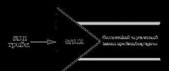
The main functional module of SDH networks is a multiplexer. SDH multiplexers perform both the functions of the actual multiplexer and the functions of terminal access devices, allowing you to connect low-speed PDH hierarchy channels directly to their input ports. they are versatile and flexible devices that can solve almost all of the above tasks, i.e. in addition to the multiplexing task, perform switching, concentration and regeneration tasks. This is possible due to the modular design of the SDH multiplexer - SMUX, in which the functions performed are determined only by the capabilities of the control system and the composition of the modules included in the multiplexer specification. It is accepted, however, to distinguish two main types of SDH multiplexer: terminal multiplexer and input / output multiplexer.
Terminal multiplexer TM is a multiplexer and an SDH network terminal device with access channels corresponding to the PDH and SDH access tribes of the hierarchy (Fig. 6). The terminal multiplexer can either insert channels, i.e. switch them from the input of the tribal interface to the line output, or output channels, i.e. switch from the line input to the output of the tribunal interface.
An ADM I / O multiplexer can have the same set of tribes at its input as a terminal multiplexer (Figure 6). It allows you to input / output the corresponding channels. In addition to the switching capabilities provided by TM, ADM allows end-to-end switching of output streams in both directions, as well as closing the receive channel to the transmission channel on both sides ("east" and "west") in case of failure of one of the directions. Finally, it allows (in the event of an emergency multiplexer failure) to pass the main optical stream past it in a bypass mode. All this makes it possible to use ADM in ring topologies.
Figure 5.1 - Synchronous multiplexer (SMUX): terminal multiplexer TM or input / output multiplexer ADM.
Regenerator is a degenerate case of a multiplexer with one input channel - as a rule, an STM-N optical tribe and one or two aggregate outputs (Fig. 7). It is used to increase the allowable distance between SDH network nodes by regenerating payload signals. Typically this distance is 15-40 km. for a wavelength of the order of 1300 nm or 40 - 80 km. - for 1500 nm.

Figure 5.2 - Multiplexer in regenerator mode
Concentrators
Concentrator(hub) is used in topological schemes of the "star" type, is a multiplexer that combines several, as a rule, of the same type (from the side of input ports) streams coming from remote network nodes into one distribution unit sDH networks, not necessarily also remote, but connected to the main transport network.
This node can also have not two, but three, four or more line ports such as STM-N or STM-N-1 (Fig.5.3) and allows you to organize branch from the main stream or ring (Fig.5.3a), or, conversely, connecting two external branches to the main stream or ring (Fig.5.3) or, finally, connecting several nodes of the mesh network to the SDH ring (Fig.5.3c). In general, it can reduce the total number of channels connected directly to the main SDH transport network. The distribution node multiplexer in the branch port allows locally switching the channels connected to it, allowing remote nodes to communicate through it with each other without loading the traffic of the main transport network.


Figure 5.3 - Synchronous multiplexer in hub mode
Switch.Physically, the capabilities of internal channel switching are incorporated in the SDH multiplexer itself, which allows us to speak of the multiplexer as an internal or local switch. In fig. 8, for example, the payload manager can dynamically change the logical correspondence between the tribunal TU and the access channel, which is equivalent to internal circuit switching. In addition, the multiplexer, as a rule, has the ability to switch its own access channels (Fig. 9), which is equivalent to local channel switching. For example, multiplexers can be assigned the task of local switching at the level of the same type of access channels, i.e. tasks solved by concentrators (Fig. 9).
In the general case, you have to use specially designed synchronous switches - SDXC, which carry out not only local, but also general or pass-through (end-to-end) switching of high-speed streams and synchronous STM-N transport modules (Figure 3.5). An important feature of such switches is the absence of blocking of other channels during switching, when the switching of some TU groups does not impose restrictions on the processing of other TU groups. such switching is called non-blocking.

Figure 8 - I / O multiplexer in the internal switch mode.

Figure 9 - I / O multiplexer in the local switch mode.

Figure 10 - General or pass-through switch of high-speed channels
There are six different functions that the switch performs:
VC routing based on the use of information in the ROH of the corresponding container;
Consolidation / Hubbing of VCs in Hub / Hub mode;
Translation (translation) of a stream from a point to several points, or to a multipoint, carried out using the "point-to-multipoint" communication mode;
Sorting or drooming of VCs to create several ordered VC streams from the general VC stream going to the switch;
Access to the virtual container VC, carried out when testing equipment;
Input / output (drop / insert) of virtual containers, carried out during the operation of the input / output multiplexer;
A well-developed international standard describing the structure of SDH signals, functions and electrical parameters of the equipment ensures the compatibility of equipment from different manufacturers. This allows for seamless interaction between operators of different networks.
Main features of SDH
SDH technology is described in ITU-T recommendations (G.702, G.703, G.704, G.707, G.708, G.709, G.773, G.774, G.782, G.783, G .784, G.957, G.958, Q.811, Q.812), ETSI (ETS 300 147). The North American Synchronous Digital Hierarchy obeys the SONET standards system developed by ANSI (American National Standards Institute) - American National Standards Institute.
Let's consider the structure of SDH signals. It is an STM-N synchronous transport module, where N is determined by the SDH layer. Currently, STM-1, STM-4, STM-16 and STM-64 systems are widely used. It is easy to see that the systems are built with multiplicity 4. Thus, the following hierarchy of speeds has been formed.
Synchronous digital hierarchy
The basic SDH layer is STM-1. It is characterized by its cycle with a repetition period of 125 μs. It is generally accepted to think of a loop as a rectangular table, although, of course, data is transmitted over the line sequentially. As you can see from the figure, the STM-1 cycle contains 9 lines of 270 bytes (2430 bytes). The first 9 bytes on each line form the loop header.
The advantages of SDH include the modular structure of the signal, when the rate of the compressed signal is obtained by multiplying the base rate by an integer. In this case, the structure of the cycle does not change and the formation of a new cycle is not required. This allows the desired channels to be extracted from the compressed signal without demultiplexing the entire signal.
The figure shows a scheme for multiplexing four STM-1 streams into one STM-4 stream. It can be seen from the figure that there is a byte multiplexing in such a way that all the section header blocks, the pointer and the payload are located as before.

PDH signals, ATM cells, any unstructured digital streams with a speed from 1.5 to 140 Mbit / s and meeting the G.703 recommendations can be transmitted as the payload of the SDH-based network. This versatility is ensured by the use of containers that carry load signals over the SDH network.
Container principle well known and quite widely used in modern communication technology. This idea turned out to be very practical, because all operations on the network are performed with containers and do not affect their contents. Thus, full transparency of the network for the transmitted information is achieved.
The formation of containers for data transmission at different rates is discussed below. All containers are placed in a part of the STM-1 cycle called Payload.
In order to avoid loss of synchronization in the SDH equipment, scrambling of the transmitted signals is provided. The fact is that useful information may contain long strings of zeros or ones. When transmitting electrical signal lines (for example, in a coaxial cable), this problem is eliminated by choosing the appropriate line signal code.
According to ITU-T G.703 recommendation, the CMI code (coded mark inversion code, two-level code with message inversion) should be used. In this code, the transmitted zero is always represented by a negative level in the first half of the message and a positive level in the second half. The transmitted unit is represented as either a positive level or a negative level, depending on the value of the previous bit.
In the vast majority of cases, optical communication lines are used to transmit STM signals. They use a linear code NRZ (non return to zero, code without return to zero).
It is to provide timing jumps in the transmitted STM signal over optical communication lines that the scrambling operation is used. The scrambler converts the original digital stream into a pseudo-random sequence. The pseudo-random sequence generator is built on the basis of a seven-bit shift register, modulo 2 adders (“exclusive OR”) and feedbacks according to the polynomial 1 + X6 + X7. The entire STM-N cycle is scrambled except for the first 9 bytes of the header. The first line of the header carries a frame sync signal, which allows synchronization without prior descrambling.
Construction of an SDH network of any complexity is provided by a rather limited set of functional units. With their help, all operations for the transfer of information and control on the network are performed.
The main functional unit of SDH is a multiplexer designed to organize input / output of digital streams with a payload. There are two types of multiplexers: terminal and input / output. The main difference between the two is their location on the network. Below, when considering typical schemes of SDH networks, this difference will be indicated.
Cross-connectors usually do not directly serve load I / O, but provide exchange between transport modules of the SDH network. Cross-connectors are used for network interconnections or complex network topologies. In addition to specialized cross-connectors, the local switching function can be performed by a multiplexer.
A number of functional units, such as regenerators, equipment of line paths and radio relay lines, ensure the functioning of the actual transmission lines of the SDH network.
An obligatory functional unit of any serious SDH network is a control system, which provides monitoring and control of all network elements and information paths.
SDH networks use two typical topological schemes: “ring” and “chain”. They are based on multiplexers. In the “ring” scheme, only input / output multiplexers (ADM -Add / Drop Multiplexer) are used, and in the “circuit” scheme - terminal multiplexers (TM - terminal multiplexer) and input / output. As you can see from the figure, each multiplexer has two pairs of trunk outputs, one is called "east" and the other - "west". With their help, various redundancy or protection schemes are provided.
Protection schemes of “1: 1” and “1 + 1” types are formed by organizing two counter streams. In the first case, signals from each direction are analyzed at the reception and the best one is selected for further processing. In the second scheme, there are two rings - primary and backup. In case of failures in the main ring, switching to the reserve one occurs, in the event of a ring break or multiplexer failure, a new ring is formed due to the organization of turns at the boundaries of the damaged section.

From the considered typical schemes or their varieties, you can create an SDH network of any architecture and any complexity.

The figure shows an abstract SDH network that includes a long-distance backbone and subnets at the ends of this backbone.
In City B, there are two ring architecture networks that are cross-connected. Through it, information flows can enter the backbone network, made according to the "chain" scheme. City A has one ring architecture network. Communication with the backbone network is carried out using an input / output multiplexer (ADM). Due to the large length of the backbone network, in the absence of the need for intermediate points of input / output of data, regenerators are used on it to ensure the restoration of the waveform. This kind of organization is rarely required. It is preferable to use I / O multiplexers instead of regenerators, which also provide digital signal regeneration.
The section of the network between two terminal multiplexers is called a route. Between two adjacent multiplexers (cross-connectors) - a multiplex section, and between two adjacent regenerators or between a regenerator and multiplexor (cross-connector) - a regeneration section.
Data placement in the STM-1 cycle (mapping)
As noted above, all payloads are transferred using containers. Let's consider the possible types of containers, their internal structure and principles of formation.
The following correspondence of containers to the transmission rates of useful information (in kbit / s) is determined:
This series of containers conforms to international recommendations (ITU-T G.709) and integrates the European and North American SDH (SONET) system schemes. The European standard does not include the C2 container.
The figure shows the general layout of signals in the synchronous digital hierarchy.

A PDH signal with a speed of 140 Mbit / s (139 264 kbit / s), when transmitted through the SDH network, is located in C-4 containers. Containers C-4 follow with a period of 125 μs. The size of the C-4 container is precisely defined and is 2340 bytes (9 lines of 260 bytes) or 18720 bits. At the same time, a container with a capacity of only 17408 bits (139 264 kbps: 8 kHz) is required to accommodate all the bits of the PDH signal at 140 Mbps. A value of 8 kHz corresponds to a repetition period of 125 µs. Thus, there is still space in the C-4 container that has not been filled with the PDH signal. This space contains:
- coarse alignment bits and bytes (constant stuffing) to match the plesiochronous signal rate with the higher container rate;
- fine alignment bits, positive stuffing is used (adding bits);
- bits with information about the presence of an exact alignment;
- "ballast" bits that have no functional purpose.
For transmission in the STM-1 stream of the C-4 container, a path or path header RON (Path OverHead) with a size of 9 bytes is added to it. As a result of this operation, a so-called VC-4 virtual container is formed, which has a size of 2349 bytes (9 lines of 261 bytes).
Since STM-1 cycles are generated continuously and synchronously with respect to the entire network, flexible stacking of VC-4 virtual containers in the STM-1 stream is used to ensure the transmission of plesiochronous signals. As shown below, the beginning of the VC-4 is allocated in one STM-1 cycle, the remainder in the next cycle.

Information about the beginning of the VC-4 virtual container, the location of its first byte is contained in the PTR (Pointer) pointer. More pointers are discussed below.
In the STM-1 cycle, the PTR and Payload are collectively referred to as the AU-4 administration unit.

The pointer is called the AU-4 pointer (AU-4 PTR). Sectional headers (SOH) are added to the AU-4 to obtain the complete structure of the STM-1 frame. The figure shows the relationship between the components of the STM-1 loop when placing the C-4 container.

In an STM-1 cycle, 3 containers of PDH signals at a rate of 34 Mbit / s (34 368 kbit / s) can be transmitted. These containers are called C-3. From a rate perspective, an STM-1 frame can carry 4 signals at 34 Mbps, but only 3 C-3 containers are used for North American SONET compatibility.
Container C-3 is 756 bytes (9 lines of 84 bytes), or 6048 bits. The repetition period of the C-3 container is 125 μs. A 34 Mbps PDH signal requires a container capacity of only 4296 bits (34 368 kbps: 8 kHz). Container C-3 is also designed to house the North American Hierarchy DS-3 signal (44 Mbps). For this, container C-3 uses only 5593 bits (44,736 kbps: 8 kHz).
The free bits left over from the payload are used in the same way as in container C-4. For exact alignment only, double-sided stuffing (adding and subtracting bits) is used.
An RON header is added to each C-3 container and the result is a VC-3 virtual container that is 765 bytes (9 lines of 85 bytes).
There are two ways to place a VC-3 in an STM-1 loop. In the first method, each VC-3 virtual container in the STM-1 cycle, more precisely in its PTR pointer, has a separate 3-byte pointer. The combination of the VC-3 container and the 3-byte pointer forms the administrative unit AU-3. The pointer is called the AU-3 pointer (AU-3 PTR) and indicates the start of the corresponding VC-3 in the STM-1 frame. In the ETSI standards describing SDH, this method is not recommended for use.
The second method is based on converting three VC-3 blocks into one VC-4 block. For this, a 3-byte pointer is added to the VC-3 virtual container, resulting in a TU-3 tributary unit. When 6 fixed alignment bytes are added to it, the tributary unit group TUG-3 is obtained.

For transmission over the SDH network, three received TUG-3s are multiplexed byte-wise into a VC-4 virtual container. The figure shows this process.

Note that two columns of fixed alignment bytes are placed in the VC-4 after the RON to match the container sizes (and therefore to match the speeds). The figure shows the relationship between the components of the STM-1 cycle when placing containers C-3, according to the ETSI recommendations.

In an STM-1 frame, 63 PDH containers can be transmitted at a rate of 2 Mbps (2,048 kbps). The container for transmitting this signal is called C-12. The repetition period of this container is 125 μs.
The capacity of the container is 34 bytes (8 lines of 4 bytes plus 1 line of 2 bytes) or 272 bits. A 2 Mbps PDH signal requires 256 bits (2,048 kbps: 8 kHz).
The free bits left over from the payload placement are used in the same way as in containers C-4 and C-3, double-sided stuffing is applied for accurate alignment.
A VC-12 virtual container is created by adding a 1-byte RON to the beginning of the container. In this case, the 9th line of the container becomes 3 bytes, i.e. all information is shifted back 1 byte.
VC-12 virtual containers are transmitted as part of a superframe (or multiframe) with a period of 500 µs. Note that a multiframe is transmitted over multiple STM-1 frames. The RON bytes of each VC-12 of one superframe constitute the summary RON header. The figure shows the components of a superframe. The meaning of the RON bytes (V5, J2, Z6 and Z7) will be explained in the description of the header.

A TU-12 tributary unit is formed by adding a pointer byte to a VC-12 container. The size of the TU-12 is 36 bytes (9 lines of 4 bytes). A TU-12 multiframe is derived from a VC-12 multiframe by adding four pointer bytes (TU-12 PTR). Only the first three bytes of the pointer matter, the fourth currently has no defined functions. These pointers will be described in more detail below.
Three TU-12s are multiplexed by byte to form a 108-byte TUG-2 (9 lines of 12 bytes). The seven TUG-2s are grouped in the same way into a TUG-3 (Figure 5.13), with one column of fixed alignment bytes added.

In the received TUG-3 group, the three bytes corresponding to the TU-3 PTR indicator are called NPI (Null Pointer Indicator) - an indicator of a "blank" (meaningless) pointer.
From the TUG-3 blocks, the STM-1 cycle is formed in the manner discussed above.
Pointers to containers
The Pointing Mechanism in SDH serves to synchronize between the various tributary signals and the STM cycle. Thanks to the pointers, there is no need for mutual agreement between the start of the SDH cycle and the cycle of the tributary signal packed in the virtual container.
The pointers are always placed at precisely defined locations in the structure of the SDH signal, so that information can be accessed without demultiplexing the entire signal. Two-way pointer stuffing is used to equalize phase and baud rate deviations.
There are three types of pointers in total:
administrative unit pointers AU, AU-4 PTR and AU-3 PTR. The latter index is used in the North American version of SDH and will not be discussed in detail. The AU-4 pointer specifies the placement of the VC-4 virtual container in the STM-1 frame;
tributary unit indicator TU-3, TU-3 PTR. This type of pointer is used by placing three VC-3 virtual containers in a VC-4 virtual container;
pointers of tributary units TU-11, TU-12 and TU-2. These pointers are used to locate the corresponding VC-11, VC-12, and VC-2 virtual containers. Each of these pointers is transmitted one byte in the first three 125 µs frames in one 500 µs multiframe. The byte at the pointer position in the fourth cycle of the multiframe is irrelevant and reserved for future use.
The AU-4 PTR and TU-3 PTR indicator bytes contain the following information:
start address of the corresponding virtual container;
new data flag;
fine alignment bits;
pointer type label (AU-4 PTR, AU-3 PTR, or TU-3 PTR). This label is currently not in use and must be fixed;
bytes to use when using negative justification.
The TU-11 PTR, TU-12 PTR and TU-2 PTR indicator bytes contain information about the start address of the corresponding virtual container and a field for negative justification.
The values \u200b\u200bof the AU-4 PRT allow only every third byte of the payload area of \u200b\u200bthe STM-1 frame to be addressed. The range of addresses in which a floating start of the VC-4 is possible begins after the AU-4 PTR at address 0 and ends at 782 in the next STM-1 frame. The figure shows the beginning of the MC-4 virtual container at address 88.

The structure of the AU-4 PTR indicator is shown below.

Bytes H1 and H2 contain the following fields:
new data flag field, bits N. This field can contain two status values \u200b\u200b“1001” and “0110”. The active status (“1001”) serves to notify the receiver that the pointer value has been changed. In subsequent cycles and during the clearing procedure, the inactive status (“0110”) is used;
the field of the label of the pointer type, bits S. Currently not used and should have a fixed value “10”;
pointer value field, 10 I and D bits. These bits have a dual purpose. They can specify a pointer value from 0 to 782 in decimal. After the transfer of the active status in bits N, the pointer value must match at least three cycles. To perform negative justification, all D - bits are inverted and in the next AU-4 PTR the pointer value is decremented by 1 (decrement operation). Positive alignment inverts all I - bits and the next cycle performs an increment operation (the pointer value is incremented by 1). Pointer adjustments are only allowed once every four cycles to ensure pointer validation.
According to ETSI recommendations, bytes “Y” and “1” are not used and must be constant. Byte “Y” contains 1001SS11, where SS coincides with the field of the pointer type label and have the same meaning. So byte “Y” \u003d “10011011”. Byte “1” always contains “11111111”. In the North American version, these bytes can be used as additional pointers.
The H3 bytes are reserved bytes for transmitting information at the time of negative alignment.
TU-3 PTR pointers are used when placing three VC-3s in one VC-4. In this case, a tributary unit TUG-3 is formed from the VC-3 virtual container by adding a 3-byte pointer (TU-3 PTR) and 6 fixed alignment bytes.

The figure shows the addressing scheme using TU-3 PTR pointers. In a VC-4, the POH bytes and the fixed alignment bytes are followed by three TUG-3s multiplexed per byte. The VC-3 start address range within a TUG-3 is 0 to 764.
In the example in this figure, the first VC-3 starts at 0, the second starts at 85, and the third starts at 594.
The structure of the bytes H1, H2 and H3 of the TU-3 PTR indicator is completely the same as that of the AU-4 PTR and a similar mechanism is used to align the phases and signal rates.

As previously indicated, the overframe VC-12 virtual containers form a TU-12 multiframe when the TU-12 PTR indicator is added. The role of this pointer is similar to the AU-4 PTR and TU-3 PTR pointers, namely to fix the start of the virtual container. In this case, the start of the VC-12 supercycle. The figure depicts the placement of a VC-12 superframe in a TU-12 superframe.
The purpose and structure of the V1, V2 and V3 bytes are the same as the H1, H2 and H3 bytes. The only difference is in the SS bits. For the considered class of pointers, the values \u200b\u200bof these bits carry a semantic load and define a specific type of pointer. For TU-11 PTR the value shall be “11”, for TU-12 PTR it should be “10” and for TU-2 PTR it should be “00”.
The ten-bit field of the TU-12 PTR pointer value can contain a value from 0 to 139. This implies that the VC-12 multiframe can be transmitted using 4 or 5 STM-1 frames. In the example in the figure, the pointer value is 0, i.e. a VC-12 multiframe starts immediately after the V2 pointer byte and requires only 4 STM-1 frames to transmit. V3 bytes are reserved and are used to transfer information at the moment of negative alignment. The alignment mechanism is similar to those discussed above.
Another special pointer is used when transferring VC-12 virtual containers in the STM-1 cycle. This is the so-called NPI marker that appears in place of the TU-3 PTR marker when VC-12s are grouped into a TUG-3.
In the NPI pointer, the new data flag field contains the active status (“1001”), and the ten-bit pointer value field has a constant, nothing meaningful value - “1111100000”. The H3 byte is naturally not used in this case, since all alignment procedures are performed at the level of the TU-12 PTR pointers.
Container and signal headers (overhead)
Headers play an important role in the transmission of payload using SDH loops. The header is always decoupled from the transmitted load. Due to this, the header bytes can be read, changed or supplemented without affecting the information itself.
The STM-1 frame header is known to have three parts:
- The PTR is an administrative unit (AU) pointer that identifies the position of the individual multiplexed signals (VC-4 and VC-3) in the STM-1 frame.
- RSOH - regeneration section header containing control, monitoring and frame synchronization signals to ensure the operability of the regeneration sections.
- MSOH - multiplex section header, provide interworking between multiplexers. They pass through the regenerators unchanged.
RSOH and MSOH jointly form a sectional header (SOH-Section Overhead). Due to this header, control and synchronization networks are formed in the STM signal, which provide the transmission of synchronization, network control, monitoring and maintenance signals, and support the service communication channels.
The figure shows a map of the distribution of the RSOH and MSOH bytes.

Consider the purpose of these bytes:
- A1, A2 - alignment signals, frame synchronization. Byte A1 contains the value “11110110”, A2 - “00101000”.
- В1 - control of errors of the regeneration section. This byte (parity) is generated from all bits of the previous frame after scrambling and is written in the current frame before scrambling.
- B2 - error control of the multiplexer section. These bytes are formed on the basis of the entire unscrambled frame except for the bytes included in the RSOH header. The result is written to the appropriate positions before scrambling.
- C1 - STM-1 cycle identifier. Assigned to each STM-1 before compaction to STM-N.
- D1 - D3 - form a 192 kbit / s data link in regeneration sections (DCC-R). Used only in the first STM-1 STM-N cycle. The DCC-R channel is used to transfer control commands and control signals between the regenerators and the network control center.
- D4 - D12 - form a data transmission channel with a speed of 576 kbit / s in multiplexer sections (DCC-M). Used only in the first STM-1 STM-N cycle. The DCC-M channel creates a communication link between the multiplexers and the control center according to ITU-T G.784 recommendation.
- E1 - forms a local service channel, which is used for voice communication between regenerators.
- E2 - similar to E1, only between multiplexers.
- F1 is the channel of the SDH network operator. Provided for own needs, data or voice transmission is possible. Used only in the first STM-1 STM-N cycle.
- K1, K2 - signaling bytes in the automatic transfer to reserve system (APS). Used only in the first STM-1 STM-N cycle. In addition to the function of providing automatic switching in byte K2, bits 6, 7 and 8 are set to “1” when an AIS (Alarm Indication Signal) is transmitted. Let's explain the purpose of the AIS signal, it is generated if an error is detected, for example, the loss of frame synchronization STM-1 - sectional AIS or an error in the virtual container - path AIS. The generated AIS is sent in the same transmission direction as the undistorted signals. Its purpose is to prevent the generation of alarms in downstream equipment. If the receiver of the multiplexer does not receive a signal or an AIS signal was received, then the combination “110” is transmitted through bits 6, 7, 8 of the K2 byte. In this way, receive errors are reported to the far end.
- S1 - serves to indicate the presence of a clock signal (for example, from the master generator) in the incoming STM-N stream. Used only in the first STM-1 STM-N cycle.
- M1 - called FEBE (Far End Block Error) and contains the number of blocks with errors detected using the B2 bytes. For STM-1, values \u200b\u200bfrom 0 to 24 make sense, and for STM-4, from 0 to 96. Other values \u200b\u200bshould not be generated.
- Z1, Z2 - reserved for still undefined functions.
- N - Reserved for national use.
- The rest of the bytes are reserved for future use.
In addition to the SOH sectional header, the ETSI recommendations define three types of path overheads (POH-Path Overhead), these are VC-4 POH, VC-3 POH and VC-12 POH.
The RON header is added to the corresponding C containers to form virtual containers. The figure below shows the header data bytes.

Consider the purpose of these bytes for VC-4 POH and VC-3 POH:
- J1 - this byte is the first byte of the virtual container and is used to transfer 64-byte information about the path of such a container. This information is transmitted cyclically, one byte at a time, every 64 cycles.
- B3 is a control byte for detecting errors in the virtual container. Before the scrambling procedure of the virtual container, this control byte is calculated for all its bytes, the parity check method is used. The formed byte is written in field B-3 of the next container, again before the procedure for calculating the control byte and scrambling.
- C2 - signal mark. Serves to indicate the contents of the virtual container. The following values \u200b\u200bfor this label are defined:
- С2 \u003d 00h - paths of VC-3 and VC-4 containers are not formed.
- C2 \u003d 01h - paths of VC-3 and VC-4 containers are formed, but there is no useful information.
- C2 \u003d 02h - VC-4 path is formed for transmission of 3 TUG-3 groups.
- C2 \u003d 12h - VC-4 path is formed to transmit a signal of 140 Mbit / s.
- C2 \u003d 13h - VC-4 channel is formed and serves for transmission of ATM cells.
- All other values \u200b\u200bare reserved for future use. - G1 - this byte is used to signal errors in the opposite direction. With the help of this byte, a message about its status and quality indicators is transmitted towards the beginning of the path. The first four bits are called FEBE (Far End Block Error) and convey the number of bad blocks identified with the B3 check byte. Values \u200b\u200bfrom 0 to 8 are meaningful, all others are interpreted as 0, i.e. as a lack of errors. The fifth bit is a failure indicator and is called FERF (Far End Receive Failure) and is set to “1” when receiving AIS, loss or error in the signal, with incorrectly formed end-to-end paths. The remaining bits of the G1 byte are not used.
- F2, Z3 - reserved for the purpose of organizing service communication lines of the network operator. There is currently no precise specification for this feature.
- H4 - indicator (counter) of the position of the payload, distributed over several cycles (multiframe when transmitting the virtual container VC-12). This indicator can be used to determine the presence of a multiframe and to identify individual multiframe cycles.
- Z4 - not used, reserved.
- Z5 - Reserved for operational purposes. It is used by the network operator both for counting incoming errors and for organizing a communication channel.
The VC-12 virtual container tract header is formed during the multiframe transmission and consists of four bytes. The figure earlier shows the allocation of these bytes within a multiframe.
V5 - this header byte is used for error detection, transmits a signal label and indicates the status of the path. For each task, the corresponding bits of this byte are predefined. Bits 1 and 2 are used for parity error detection. Bit 1 provides parity for the odd (byte counts 1, 3, 5, and 7) bits of all bytes in the previous VC-12 virtual container. Accordingly, bit 2 is used to check the parity of the even (byte counts 2, 4, 6 and 8) bits. No parity is performed on the V1, V2, V3, and V4 bytes forming the TU-12 pointer. An exception is the V3 byte in the case of a negative justification. Bit 3 is the FEBE indicator set by the receiving side and evaluated by the transmitting side. It is a kind of feedback. If at least one error is detected with the help of 1 and 2 bits, it is set to the value “1” and this informs the source of the path about the presence of errors. If no errors were found, then its state is "0". Bit 4 is not used. Bits 5, 6, and 7 carry the cue. A value of “000” indicates that the VC-12 container path is not formed. Value “001” - the path is formed, but not defined (not a standard signal is transmitted). Value “010” - an asynchronous signal is transmitted. Value “100” - a synchronous signal is transmitted. The remaining combinations of values \u200b\u200b(“101”, “110”, “111”) indicate that the path has been formed and reserved for future use. Bit 8 is the alarm indicator, FERF signal. It is set to “1” and informs the transmitting side of signal loss or AIS reception.
J2 - used to transmit a path label, which allows tracking the continuity of a connection along the path.
Z6, Z7 - Reserved for future use.
The figure shows the areas of “responsibility” for each type of title.

Error control and management in SDH networks
Monitoring and control procedures are carried out on the SDH network using the appropriate bytes and bits of the STM frame and virtual container headers.
To detect bit errors, the parity check procedure or BIP (Bit Interleaved Parity) is used. This procedure is based on the method of adding “1” to an even number. If there is an odd number “1” in some bit sequence, then an additional “1” is set in the check bit. And vice versa, if the number “1” is even, then “0” is set in the check bit.
SDH uses codewords of various lengths to provide parity. The principle of forming these words is the same. The entire monitored bit sequence is conventionally divided into blocks equal to the length of a specific codeword. Then the resulting blocks are added bit by bit in accordance with the "exclusive OR" rule. The result is the desired control codeword. In other words, the counting of the number "1", standing in the corresponding bit positions.
The received codeword is transmitted in the corresponding header of the next STM frame or virtual container. On the receiving side, the code word is calculated again and compared with the received word from the next information block. If these words match, then a conclusion is made about the reception without distortion. The code words used in SDH are shown in the figure:

The regeneration section uses the BIP-8 word located in the B1 byte of the RSOH. This word is formed from all bits of the frame after the scrambling operation and placed in byte B1 of the next frame before scrambling. Recall that the entire frame is scrambled except for the first 9 bytes of the RSOH. The BIP-8 word is checked in every multiplexer and regenerator.
In the section of the multiplex section, the BIP24 codeword is used, which is located in the B2 bytes of the MSOH. This is true for the STM-1 cycle. When using STM-N, the codeword will be BIP-Nx24. The BIP-24 codeword is formed before the scrambling operation from the entire STM-1 cycle, except for the first 3 SOH rows (this is RSOH). The resulting value is placed in the B2 bytes of the next cycle before scrambling. Thus, the BIP-24 value does not change in the regenerators.
The VC-3 and VC-4 virtual containers use the BIP-8 codeword located in byte B3 of the POH. This word is formed from all bits of the virtual container and placed in the RON of the next container. Pointer bits are not taken into account when generating BIP-8.
For the VC-12 virtual container, the BIP2 codeword is used, which is located in bits 1 and 2 of the V5 byte of the RON path indicator. The BIP-2 word is formed from the entire VC-12 superframe and is placed on the subsequent superframe. The figure shows the actions of each BIP type.

The received side generates several types of signals carrying emergency information. There are two types of signals - error indicators. These are FEBE (Far End Block Error) - a block error at the far end and FERF (Far End Receive Failure) - a failure when receiving at the far end. Distinguish between track and sectional signals.
First, consider the conditions for the formation of the FEBE signal. This signal is sent to the transmitting side to report detected errors using BIP codewords.
Bits 1-4 of the G1 byte of the RHN header are used to transmit the path FEBE of the VC-3 and VC-4 virtual containers. For BIP-8, a maximum of 8 parity violations can be detected. The FEBE code contains the number of such violations and can range from 0 to 8. All other values \u200b\u200bare interpreted as 0.
Bit 3 of the V5 byte of the ROH path header is used to transmit the FEBE of the VC-12 virtual container. If this bit is “0”, then no parity violations were detected in the BIP-2 codeword.
The M1 byte of the MSOH is used to transmit the sectional FEBE of an STM-1 frame. For STM-1, FEBE can be from 0 to 24, and for STM-N, from 0 to Nx24.
The FERF signal notifies the transmitting side that an AIS signal is detected at the receiving side or that it cannot receive. Here we are talking about receiving signals from SDH multiplexers located further down the chain. Those. the FERF alarm moves in the same direction as the transmitted signal.
For VC-3 and VC-4 virtual containers, the FERF path signal is transmitted in bit 5 of the G1 byte. For this, it is set to “1”. For a VC-12 virtual container, the FERF signal is transmitted by bit 8 of the V5 byte. FERF tract signal is set if:
for BIP-8, the Bit Error Rate BER is greater than or equal to 10 -4;
there is an error in byte J1, distortion of information about the route of the virtual container;
no virtual container signal.
The FERF signal for STM-1 is transmitted in bits 6 - 8 of the K2 byte, the value is 110. The sectional FERF is set if:
for BIP-24, the BER is greater than or equal to 10 -3;
an AIS signal is detected in a section header;
loss of FAS framing signal;
loss of STM-1 signal.
AIS signal (Alarm Indication Signal) - an alarm indication signal is generated when a number of errors are detected in the received signal. The purpose of the AIS signal is to prevent the generation of error messages in downstream multiplexers or regenerators. Reception of the AIS signal triggers responses (such as blocking a channel) only in certain terminal equipment.
AIS signal is used in PDH and SDH. In SDH, when an AIS signal is detected, the STM-1 or STM-N frame is fully preserved and passed on. In PDH, this signal indicates the impossibility of FAS framing in further sections. This is because the frame sync bytes and the PDH addendum are logged. “1” to transmit AIS signal.
SDH distinguishes between path AIS and sectional AIS. Tract AIS corresponds to virtual containers of the SDH hierarchy. For tributary units TU - 1, 2, 3, the pointer is set to “1” in the case of AIS TUs. For administrative units AU - 3, 4, the pointer is set to “1” at AIS AU. These constant signals are transmitted in the STM-1 frame as corrupted tributary blocks.
Control and monitoring signals on SDH networks are carried in RSOH and MSOH headers using D bytes. In an STM-N frame, only the first STM-1 D bytes are used to carry these signals.
To organize technological communication between the components of the geographically distributed SDH network, voice communication channels are used. These channels are formed by the E bytes of the RSOH and MSOH.
Since in each set of communication center equipment, transmission is simultaneously carried out in one direction and reception in the other, a multiplexer and a demultiplexer are mounted in one unit, performing reciprocal functions of combining / disconnecting (splitting) streams.
SDH multiplexers, unlike PDH multiplexers, perform both multiplexing functions and the functions of a terminal device for accessing low-speed RDH hierarchy channels directly to their input ports. In addition, they can also perform switching, concentration and regeneration. Structurally, SDH multiplexers (SMUX) are made in the form of modules. By changing the composition of the modules and control software, the above-mentioned SMUX functions can be provided. However, there is a difference between terminal SMUX and SMUX I / O.
Terminal multiplexer (TM SMUX) is a multiplexer / demultiplexer and, at the same time, an SDH network terminal device with access channels corresponding to the PDH and SDH hierarchies tribes. TM SMUX can input channels (tributary streams) and switch them to the line output or it can switch line signals to the tributary outputs, i.e. output. In addition, it can perform local switching of the input of any tribal interface to the output of the same interface. (i.e., it grinds the tribal flows at the inlet, though for flows 1.5 and 2.
Because SDH system was developed for optical communication lines, then MUX also have output interfaces for optical communication lines. Only STM-1 can have either electrical or optical line outputs, while STM-4; 64 have only optical inputs / outputs.
Moreover, it turned out to be easy to have two line inputs (each provides simultaneous reception and transmission), they are also called the optical aggregate receive / transmission channel.
The presence of two aggregate channels allows you to organize reception / transmission over different types of network structure: ring, linear, star-shaped, etc. With a ring network, this is a great advantage of SDH MUXs, one direction - "west", and in the other direction - "east".
 |
With a linear network structure, these outputs are called primary and backup.
Ring structure
I / O multiplexer-ADM (Add / Drop Multiplexer) (or Drop / Insert) - can have at the output the same set of devices as the terminal one and can output from the general stream or insert component tributary streams into it, carry out switching and, in addition, allows (transit) passage of the entire flow with simultaneous signal regeneration. ADM can also short-circuit (loop) aggregate optical outputs "east" to "west" and vice versa. This allows switching the flow to another in case of failure of one line, i.e. reservation is in progress. In addition, if the ADM unit itself fails, it is possible to pass optical signals bypassing the multiplexer itself, i.e. bypassing.

Concentrator (sometimes they are called HUB in the old way) is a multiplexer that combines several (usually of the same type) streams from the input ports coming from remote network nodes into one distribution node of the SDH network. This makes it possible to organize star structures. Below is an example of organizing a network segment.
Hubs can reduce the total number of ports connected directly to the main transport network. The distribution unit multiplexer in a star structure allows
locally switch between remote nodes without the need to connect them to the main backbone.
 |
Regeneratorsis also a multiplexer (often simpler devices). The regenerator has one optical input of the STM-N tribe and one or two optical aggregate outputs.
The regenerator restores the shape and amplitude of the pulses that have undergone line attenuation. Regenerators, depending on the laser wavelength used and the type of cable, are installed every 15-40 km. There are developments for longer wavelength optical fiber lasers with attenuation less than 1 dB / km. This makes it possible to install regenerators after 100 km or more, and with optical amplifiers and after 150 km.
Switches- the vast majority of ADM multiplexers produced by different manufacturers are built on a modular type. Among these modules, the central place is occupied by the CROSS-COMMUTATOR module, or is often called simply the SWITCH (DXC). The cross switch can carry out INTERNAL switching and LOCAL switching.

Also, the capabilities allow you to flexibly organize communication and, which is very important, allow you to perform routing. If you switch locally the same type of channels, then the switch will also act as a hub.
For SDH systems, specially designed SDXC synchronous switches have been developed, performing not only local, but also general - cross-cutting switching (or also called PASSING) of high-speed streams (34 mb / s and higher) and the possibility of NON-BLOCKING COMMUTATION - i.e. when switching any channels, the rest should not be blocked.
 |
Currently there are several varieties of SDXC switches. Their designation has the form SDXC n / m, where n is the VC number that can be received at the input, m is the maximum possible VC level that can be switched. Sometimes a whole set of VC numbers are specified that can be switched.
SDXC 4/4 - and accepts and switches VC-4 or 140 and 155 Mbps streams.
SDXC 4/3/2/1 - accepts VC-4 or 140 and 155 Mbit / s streams, and switches (processes) VC-3; VC-2; VC-1 or 34 or 45.6 Mb / s streams; 1.5 or 2 Mbps.
SHD equipment
The SDH multiplexer is designed for building fiber-optic communication networks with integrated TDM and Ethernet traffic. The equipment operates according to FOCL topology "ring", "star", "chain", as well as mixed schemes. The ability to transfer joint information streams from PDH and Ethernet systems is used to create high-capacity backbone networks.
SDH multiplexers provide standardization of network operation modes, their administration and modernization. Unified standards for building fiber-optic networks allow combining devices from different manufacturers and optimizing communication processes.
World standards and data transfer rate of SDH equipment
Advantages of using domestic SDH multiplexers
The SDH multiplexer increases the reliability of networks, helps to reduce the cost of building and upgrading them, automates control over the entire system and eliminates the risk of a sudden disconnection due to the ability to switch to backup channels. Significant savings in network maintenance costs are achieved by reducing the total amount of equipment.
Ethernet SDH technology, developed for telecom operators, allows you to quickly and efficiently broadcast data over E1 channels. The rich functionality of the equipment, management via the web interface, the shortest time to transform and switch to additional channels confirm that these technologies are of the future.
Russian Telephone Company LLC offers affordable prices for Russian-made Ethernet SDH equipment. All modifications are certified and fully adapted to work in Russian communication networks. We sell equipment directly from leading manufacturers in Russia, so we can always adjust the delivery time, offer high-quality service and technical support.
The catalog contains products:
The specialists of Russian Telephone Company LLC will help you choose optical PDH multiplexers, telecommunication cabinets and all the necessary equipment for communication networks. We guarantee an individual approach and favorable terms of cooperation for each client.
Digital multiplexers are logical combined devices that are designed for controlled transmission of information from multiple data sources into a single output channel. In fact, such a device consists of several digital position switches. Accordingly, we can conclude that it is a switch of input signals into one output line. This article will consider a separate type of devices - SDH optical multiplexers.
Such devices are designed to work with using light beams that differ in amplitude or phase as well as wavelength. SDH multiplexers transmit information over E1 channels and Ethernet lines in transport fiber-optic networks. They work on one or two optical or multimode) at a speed of 155, 520 Mbps at a wavelength of 1550/1310 nm. SDH multiplexers allow to implement up to 126 communication points.
The advantages of such devices include resistance to external influences, technical safety, protection against hacking of transmitted information.
SDH-multiplexers are easily scalable by including in the main module up to three additional modules for transmitting Ethernet channels, E1 streams, service communication, and an PM channel.

These devices are characterized by high network "survivability". The implementation has a low jitter value, due to this, the norms for E1 are observed during clock drift, as well as during synchronization failure of the STM-1 system. The interface parameters allow you to track the error in and switch to a spare channel. The optical path and power supply are reserved according to the 1 + 1 scheme. That is, when working over one fiber-optic channel, in case of cable damage, the connection between the subscribers is maintained.
SDH multiplexers are easily combined with other SDH equipment. They can operate in both synchronous and asynchronous modes, using multimode and singlemode fiber is allowed. The SDH multiplexer supports remote configuration and management via TCP / IP, 10/100 BaseT.
Such switching devices are usually divided into two types: terminal and I / O. The difference between these types is not in the composition of the ports, but in the placement of the device in the SDH network. The terminal multiplexer completes the aggregate among them a large number of input and output channels. The second type of devices transmits aggregate lines in transit, occupying an intermediate position on the highway. In this case, the information of the tributary channels is removed from the aggregate stream or entered into it.

Most manufacturers produce universal SDH type multiplexers, which are used as input / output, terminal, and cross-connectors - depending on the modules installed in them with tributary and aggregate ports.
In conclusion, we add that fiber-optic multiplexers are gaining more and more popularity due to the intensive development of this type of communication. The future belongs to fiber optic technologies.