LECTURE
Logical data models.
Hierarchical, network, relational data models.
Construction principles.
Advantages and disadvantages
In the process of development of the theory of database systems, the term "data model" had different contents. For a deeper understanding of the essence of individual concepts, let us consider some features of the use of this concept in the context of the evolution of databases.
11.1. About the concept of "data model"
Initially, the concept of a data model was used as a synonym for the data structure in a particular database. The structural interpretation was fully consistent with the mathematical definition of the concept of a model as a set with relations specified on it. But it should be noted that the object of modeling in this case is not data in general, but a specific database. The development of new architectural approaches based on the ideas of a multi-tier DBMS architecture has shown that it is no longer enough to consider the display of views of a specific database. A meta-level solution was required that would allow one to operate on the sets of all possible admissible database representations within a given DBMS or, equivalently, with the tools used to specify them. In this regard, the need arose for a term that would denote a tool, not a simulation result, and thus would correspond to a variety of different databases of a certain class. Those. a database modeling tool should include not only data structuring tools, but also data manipulation tools. Therefore, the data model in the instrumental sense began to be understood as an algebraic system - a set of all kinds of admissible data types, as well as relations and operations defined on them. Later, this concept began to include also integrity constraints that can be imposed on data. As a result, the problem of displaying data in multi-level DBMS and distributed database systems began to be considered as a problem of displaying data models.
It is important to emphasize that for developers and users of a DBMS, the exact definition of the data model implemented in it is actually the language means for defining data and manipulating data. Therefore, it is inappropriate to identify such a language with the database schema (the result of modeling) - a specific specification in this language.
Since the mid-70s, under the influence of the concept of abstract types proposed at that time, the very concept of a data type in programming languages \u200b\u200bbegan to transform in such a way that not only structural properties, but also elements of behavior (data changes) began to be put into it. In the future, this served as the basis for the formation of the concept of an object, on which modern object models are based.
In this regard, a new approach was proposed, in which the data model is considered as a type system. This approach provided natural opportunities for the integration of databases and programming languages, contributed to the formation of the direction associated with the creation of so-called database programming systems. The treatment of a data model as a type system is matched not only by existing widely used models, but also by object models gaining more and more influence.
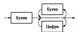
So, the data model is a model of the logical level of database design. It can be seen as a combination of three components (slide 2):
1. Structural component, i.e. a set of rules by which the database can be built.
2. A control component that determines the types of allowed operations with data (this includes operations for updating and retrieving data, as well as operations for changing the database structure).
3. Support for a set of (optional) data integrity constraints to ensure that the data used is correct.
From the point of view of the structural component, record-based models are distinguished. In a record-based model, the data structure is a combination of several types of fic records formatted. Each record type defines a fixed number of fields, each of which has fixedstraight length.
There are three main types of record-based logical data models (slide 3):
- relational data model (relational data model);
- network data model;
- hierarchical data model (hierarchical data model).
Hierarchical and network data models were created almost ten years earlier than the relational data model, therefore their relationship with conceptstraditional file handling is more obvious.
11.2. Relational data model
The relational data model is based on the concept mathematical relations.In the relational model, data and relationships are represented as tables, each with several columns with unique names. On the slide ( slide 4 ) shows an example of a relational schema , containing information about the departments of the university and the staff. For example, from the table "Personnel structure" it is clear that employee Ivanov I.I. works in the position of head of department 22, which, according to the data from the table "Structure", is located in building A, in room 322. It is important to note here that there is the following connection between the relations "Personnel" and "Structure": employee worksat the department. However, there is no explicit connection between these two relations: its existence can be noticed only if you know that the attribute Caf in relation to "Personnel" is equivalent to the attribute Caf in relation to "Structure".
It should be noted that in the relational data model, the only requirement isthe key is to make the database look like a collection of tables from the user's point of view. However, this perception applies only to logicaldatabase structure, i.e. to the external and conceptual levels of architecturesaNSI / SPARC tours ... It does not refer to the physical structure of the database, buttoraya can be implemented using a variety of storage structures.
On slides ( slides 5, 6 ) the relational data model for the SbA "employees-projects-parts-suppliers" is presented.
11.3. Network data model
In the network model, data is represented as collections records,and links in the form sets.In contrast to the relational model, links here are explicitly modeled by sets, which are implemented using pointers ( slide 5 ). The network model can be represented as a graph with records in the form knotsgraph and sets in the form of its ribs.The slide shows an example network diagram for the same datasets shown in the relational model.
The most popular network DBMS is the systemIDMS / R from Computer Associates.
On slides ( slides 8, 9 ) the variants of the network data model for the SbA "employees-projects-details-suppliers" are presented.
11.4. Hierarchical data model
The hierarchical model is a limited subtype of the network model. It also presents data as collections records,and connections - how sets.However, in a hierarchical model, a node can only have one parent. The hierarchical model can be represented as a tree graph with entries in the form of nodes (also called segments)and sets in the form of edges ( slide 6 ). The slide shows an example of a hierarchical diagram for the same datasets shown in the previous models.
The most common hierarchical DBMS is the systemIBM Corporation IMS although it also possesses some other non-hierarchical features.
On slides ( slides 11, 12 ) the options of the hierarchical data model for the SbA "employees-projects-parts-suppliers" are presented.
11.5. Advantages and disadvantages of models
Record-based (logical) data models are used to define the overall structure of the database and high-level descriptions of its implementation. Their main drawback is that they do not provide adequate means to explicitly indicate the constraints on the data. At the same time, object data models lack means of specifying their logical structure, but by providing the user with the ability to specify data constraints, they allow to better represent the semantic essence of the stored information.
Most modern commercial systems are based on a relational model, while the earliest database systems were built on a network or hierarchical model. With the latter two models, the user is required to know the physical organization of the database to which he is to access. When working with a relational model, data independence is provided to a much greater extent. Therefore, if a declarative approach is adopted in relational systems for processing information in a database (i.e., they indicate what kinddata should be extracted), then in network and hierarchical systems - the navigation approach (i.e. they indicate, asthey should be removed).
Networking and hierarchical structures are mainly focused on ensuring that the links between data are stored along with the data itself. Such unification was realized, for example, by data aggregation (construction of complex conceptual structures and data) or by the introduction of a reference apparatus that fixes semantic relationships directly in the data record.
The tabular form of information presentation is the most common and understandable. In addition, such semantically more complex forms as trees and networks, by introducing some redundancy, can be reduced to tabular ones. The links between the data will also be presented in the form of two-dimensional tables.
The relational approach, which is based on the principle of separating data and relationships, provides, on the one hand, data independence, and on the other, simpler ways of implementing storage and updating.
Multidimensional models, commercial implementations of which appeared in the early 90s to support OLAP technologies, represent a certain extension of the model of universal relations with new operational capabilities that provide, in particular, the data aggregation functions necessary for OLAP. Thus, multidimensional models are a special kind of relational models.
11.6. Document systems and model integration
The above provisions have been developed and are indeed widely used for databases of well-structured information. However, today one of the most important problems is to ensure the integration of heterogeneous information resources, and in particular, semi-structured data. The need to solve it is associated with the desire to fully integrate database systems into the environment of Web technologies. At the same time, it is no longer enough to simply provide access to the database in the traditional way “from under” HTML forms. Integration is needed at the model level. And in this case, the problem of semantic interoperability of information resources is reduced to the task of developing tools and technologies that provide for an explicit specification of metadata for semi-structured data resources based on traditional modeling technologies from the field of databases.
It is to achieve this goal that intensive development is directed.WWW - the consortium of the XML language and its infrastructure (in fact, a new data model for this environment), the document object model and other means that, as can be expected, will soon become the basis of information resource management technologies. This direction is connected with another global problem - the organization of distributed heterogeneous information systems based on the construction of metadata repositories (this concept in classical works on database design corresponds to the concept of a data dictionary), providing the possibility of semantic identification of resources and, thus, the possibility of their purposeful reuse.
Logical model- graphical representation of the database structure, taking into account the accepted data model (hierarchical, network, relational, etc.), independent of the final implementation of the database and the hardware platform. In other words, it shows WHAT is stored in the database (objects of the domain, their attributes and relationships between them), but does not answer the question HOW (Fig. 1).
Description of the subject area:
Wholesale factoryoh warehouse
The warehouse supplies parts made of certain materials (cast) from a given circle of suppliers (permanent or random) from different cities.
Legal entities and individual entrepreneurs can act as suppliers, and these groups are described by their own set of characterizing attributes; legal entities - number and date of state. registration, name, legal address, form of ownership; entrepreneurs - TIN, full name, insurance policy, passport number, date of birth.
When registering a delivery, the date, quantity and cost, type of packaging and delivery method (road transport, railway transport, self-pickup) are taken into account, and one delivery may include several types of parts.
Suppliers become permanent suppliers if they have delivered more than 1,000,000 rubles a year.
The parts are released to the workshops of the plant, taking into account the date, quantity and number of the workshop. The current quantity of goods in the warehouse is maintained.
Figure: 1. Logical database model in IDEF1X notation
IDEF1 methodologyX- one of the approaches to data modeling based on the concept of "entity - relationship" ( Entity - Relationship), proposed by Peter Chen in 1976.
|
Table 2.1. Basic elements of IDEF1X notation |
|
|
The essence(Entity) |
Graphic image |
|
Independent entity |
Name Unique identificator Attributes
|
|
Dependent entity |
Attributes |
|
Communication(Relationship) |
Graphic image |
|
Non-identifying relationship | |
|
Identifying relationship | |
|
Many-to-many relationship | |
|
Inheritance (generalization) Incomplete |
Parental. |
Independent essence Is an entity whose unique identifier is not inherited from other entities. Drawn as a rectangle with straight edges.
Dependent entityIs an entity whose unique identifier includes at least one relationship with another entity. For example, a document line cannot exist without the document itself (it depends on it). It is depicted as a rectangle with rounded edges.
The IDEF1X methodology is focused on the design of relational database models. The relational model is based on the concept of a normalized relationship (table). In this case, the entities of the subject area are displayed in database tables (Fig. 2) with the following properties:
Figure:  2. Relational database table
Key - a column or group of columns whose values \u200b\u200buniquely identify each row.
There can be several keys in one table: one primary, through which the binding of relations is carried out, and others - alternative. Key properties:
uniqueness (there can be no rows with the same key);
non-redundancy (removing any attribute from a key deprives it of its uniqueness properties)
Relational databaseIs a set of interconnected relationships. Relationships are defined using foreign keys (FK), i.e. attributes that are otherwise Primary keys (PK).
The main constraints on the integrity of the relational model are:
attributes from the primary key cannot be undefined (object integrity);
secondary keys cannot take on values \u200b\u200bthat are not among the values \u200b\u200bof the primary keys of the related table: if the relation R2 has some foreign key (FK) among its attributes, which corresponds to the primary key (PK) of the relation R1, then each FK value must be equal to one from PK values.
Creating a Logical Database Model in Visio
|
To create the Logical Database Model in Visio2013, select the "Programs and Databases" template category, and in it the "Database Model Diagram" template (Fig. 2.3) |
Figure: 2.3. Database Model Schema Template |
|
Before starting to create the Logical Model, go to the "Database" tab and set the following settings in the "Show parameters" (Fig. 2.4-2.6). |
Figure: 2.4. Document parameters ("General" tab) |
|
Figure: 2.6. Document parameters ("Relationship" tab) |
Figure: 2.5. Document parameters ("Table" tab) |
|
To create the "Part" Entity, drag the Entity stereotype from the toolbar onto the screen (Fig. 2.7). |
Figure: 2.7 Creating an Entity |
|
Set the name of the Entity in the properties at the bottom of the screen (Fig. 2.8). |
Figure: 2.8. Entity Properties ("Definition") |
|
Then, on the Columns tab, create the attributes of the Entity, mark the unique identifier (primary key) with a tick in the PK column and click the "OK" button (Fig. 2.9). |
Figure: 2.9. Entity Properties ("Columns") |
|
Similarly create a second entity, for example "Material". To create a connection between them, drag the "Ratio" stereotype with a point onto the image of the "Part" class, since zero, one or several parts are made from each material. Then drag the other end of the link onto the image of the "Material" class (Fig. 2.10). The foreign key Material Code (FK) will automatically appear in the attributes of the Part entity. An open diamond on the Material side means that the material may not be specified. To remove the diamond, open the properties of the "Part" entity and check this attribute in the "Required" column. |
Figure: 2.10. Properties of a relation ("Definition") |


The task : build a logical database model in accordance with the description of the subject area from your variant of the task.
BPwin and Erwin. CASE-tools for the development of information systems Maklakov Sergey Vladimirovich
2.1.1. Physical and logical data model
2.1.1. Physical and logical data model
ERwin has two levels of model presentation - logical and physical. Logic level - it is an abstract view of data, it presents the data as it looks in the real world and can be called what it is called in the real world, for example, "Loyal customer", "Department" or "Employee's last name". Model objects represented at the logical level are called entities and attributes (more about entities and attributes will be discussed below). A logical data model can be built on the basis of another logical model, for example, based on a process model (see Chapter 1). The logical data model is universal and has nothing to do with a specific DBMS implementation.
Physical model data, on the contrary, depends on the specific DBMS, in fact, being a display of the system catalog. The physical model contains information about all database objects. Since there are no standards for database objects (for example, there is no standard for data types), the physical model depends on the specific implementation of the DBMS. Consequently, several different physical models can correspond to the same logical model. If in a logical model it does not matter what specific data type has an attribute, then in a physical model it is important to describe all information about specific physical objects - tables, columns, indexes, procedures, etc. The division of the data model into logical and physical allows solving several important tasks.
Documenting the model. Many DBMSs have a restriction on object naming (for example, a restriction on the length of a table name or a ban on the use of special characters - spaces, etc.). Often, IS developers are dealing with non-localized versions of the DBMS. This means that database objects can be called short words, only in Latin characters and without the use of special characters (that is, you cannot call a table a sentence - only one word). In addition, database designers often abuse "technical" names, as a result of which the table and columns receive type names RTD_324 or CUST_A12 etc. The resulting structure can be understood only by specialists (and most often only by the authors of the model), it is impossible to discuss it with subject matter experts. Dividing the model into logical and physical solves this problem. At the physical level, DB objects can be named as required by the DBMS constraints. At the logical level, you can give these objects synonyms - names that are more understandable to non-specialists, including in Cyrillic and using special characters. For example, the table CUST_A12 may match essence Regular customer. This alignment allows for better documentation of the model and provides an opportunity to discuss the data structure with domain experts.
Scaling. Creating a data model usually starts with creating a logical model. After describing the logical model, the designer can select the required DBMS and ERwin will automatically create the corresponding physical model. Based on the physical model, ERwin can generate a DBMS system catalog or a corresponding SQL script. This process is called Forward Engineering. Thus, scalability is achieved - by creating one logical data model, you can generate physical models for any DBMS supported by ERwin. On the other hand, ERwin is able to recreate the physical and logical data model (Reverse Engineering) from the contents of the system catalog or SQL script. Based on the obtained logical data model, you can generate a physical model for another DBMS and then generate its system catalog. Therefore, ERwin allows you to solve the problem of transferring data structures from one server to another. For example, you can transfer the data structure from Oracle to Informix (or vice versa) or transfer the structure of dbf files to a relational DBMS, thereby making it easier to move from a file-server to a client-server IS. Note, however, that the formal transfer of the structure of "flat" tables to a relational database management system is usually inefficient. In order to benefit from the transition to client-server technology, the data structure must be modified. The forward and reverse engineering processes will be discussed below.
To switch between the logical and physical data model, use the selection list on the left side of the Erwin toolbar (Fig. 2.1).
Figure: 2.1. Switching between logical and physical model
When switching, if the physical model does not already exist, it will be created automatically.
From the book Assembling a computer with your own hands author Vatamanyuk Alexander IvanovichThe ISO / OSI Model and Data Transfer Protocols Central to the standardization of networks and everything related to them is the Open System Interconnection (OSI) model developed by the International Standards Organization (ISO). On practice
From the book C ++ Reference Manual author Stroustrap BjarnR.5.15 Logical operation OR logical-expression-OR: logical-expression-AND logical-expression-OR || boolean-expression-IOperations || are performed from left to right. The result of the operation is 1, if one of its operands is nonzero, otherwise the result is 0. Unlike | at
From the book The C # 2005 Programming Language and the .NET 2.0 Platform. author Troelsen Andrew.NET 2.0 Data Provider Source Model In NET 2.0, a data provider source model is provided that you can use to build a single base code for accessing data using generic types. Moreover, using application configuration files (in particular, their
From the book Database Handling with Visual Basic® .NET author McManus Jeffrey PCHAPTER 4 The ADO.NET Model: Data Providers At times, it seems that before database developers have gotten used to a new technology, Microsoft has come up with a completely new database access model. This chapter focuses on the ADO.NET model,
From the book TCP / IP Architecture, Protocols, Implementation (including IP version 6 and IP Security) by Faith Sidney M20.2.1 Logical database SNMP uses a database model. Each networked system contains information about configuration, current state, errors, and performance. This information can be accessed by a network administrator. She is seen as
From the book Public Key Infrastructures author Polyanskaya Olga YurievnaPhysical topology A PKI system, in addition to performing a number of functions - issuing certificates, generating keys, managing security, authenticating, recovering data - must provide integration with external systems. PKI needs to interact with
From the book Modeling Business Processes with BPwin 4.0 author Maklakov Sergey Vladimirovich3.1. The Data Model and Its Correspondence to the Process Model The BPwin functional model is the basis for building the data model. Indeed, without information about how the enterprise operates, it makes no sense to build a data model. It is convenient to build a data model
From the book Firebird DATABASE DESIGNER'S GUIDE by Borri HelenData model<> database The "world" that was obtained during the description and analysis is a draft for your data structures. A logical model is believed to describe relationships and sets. A common mistake (and the trap common to all CASE tools) blindly
From the book The World of InterBase. Architecture, administration and development of database applications in InterBase / FireBird / Yaffil author Alexey Kovyazin From the book IT Security: Is It Worth Risking a Corporation? author McCarthy LindaPhysical Security Keep servers and sensitive or critical client machines in areas with well-locked doors. If you have FAT32 installed on your servers or workstations, any user who locally connects to one such
From the book Data Recovery 100% author Tashkov Petr AndreevichThe Physical Structure of a Database Why study the physical structure of a database? When talking about the physical structure of an InterBase database, we usually mean what data is in terms of the low-level data organization - down to the byte level. Many
From the book UNIX Operating System author Robachevsky Andrey M. From the author's bookPhase One: Physical Security To start the game, I had to put on a suit and fulfill my role. My goal was to break into the computer room without obtaining official permission. Putting on the suit, I got to the point - I looked like my own. Maria offered me
From the author's bookLogical Organization Before moving on to flash drive file systems, you need to think about the NAND architecture. In this frequently used memory, information is read, written, and deleted only in blocks; on hard and floppy disks, the block size is 512
From the author's bookLogical organization of data The logical organization of laser disks refers to the file systems created on their tracks. For laser disks, unlike hard drives, floppy disks or semiconductor drives with their FAT and NTFS systems, are used
From the author's bookVirtual and physical memory RAM is perhaps one of the most expensive components of a computer system. Early UNIX systems had 64 KB of RAM at their disposal, and this amount was clearly insufficient, modern computers
Logical models
Logical models use the language of predicate calculus. The first predicate corresponds to relationship name , and the term arguments - objects ... All boolean expressions used in predicate logic have values true or falsely.
Example: consider the expression John is an Information Technology Specialist... This expression can be represented as follows: is (John, Information Technology Specialist)... Let X - an object ( John), who is an information technology specialist. Then the following notation is used: is an ( X, information technology specialist).
Expression: Smith works for IBM as a specialistcan be represented as a predicate with three arguments: works (Smith, IBM, specialist).
When working with logical models, the following rules must be observed:
1. The order of the arguments should always be specified in accordance with the interpretation of predicates accepted in the given subject area. The programmer decides on a fixed order of arguments and respects it from start to finish.
2. The predicate can have an arbitrary number of arguments.
3. Individual statements, consisting of a predicate and associated arguments, can be combined into complex statements using logical connectives: AND (END,), OR (or,), NOT (not, ~), → - implication used to formulate rules in the form : IF…, TO…
Let's look at a few examples:
1 ) Predicate name - is an.
Is (Smith, IT Specialist) ∩ reads (Smith, literature).
Smith is an IT professional and reads literature.
2 ) Predicate name - reports.
Reports (Smith, John) → leads (John, Smith).
If Smith reports to John, then John leads Smith.
3 ) Predicate name - wrote.
Posted by (Smith, program) ∩ NOT works (program) -\u003e debug (smith, program, evening) OR transfer (program, programmer, next day).
IF Smith wrote the program AND it does not work, TO Smith should debug the program tonight. OR transfer to the programmer the next day.
Variables can also be used as arguments in statements. In this case, to work with variables, the concept is introduced quantifier .
There are two types of quantifiers:
1 ... The quantifier of universality.
2. The quantifier of existence.
(x ) means that all values \u200b\u200bof the variable in parentheses related to a certain area must be true.
(x ) means that only some of the values x truth.
And they can be part of each other.
Examples of:
1 . (x ) (IT specialist ( X )→programmer(X)).
All IT professionals are programmers.
2 . (x ) (IT specialist ( X )→good programmers(X )).
Some IT Pros Are Good Programmers.
3 . (x ) (y ) (employee ( X ) → manager ( Y , X )).
Every employee has a leader.
4 . (Y ) (X ) (employee ( X ) → manager ( Y , X )).
There is a certain person who leads everyone.
Questions:
1 ... What is artificial intelligence?
2 ... What is an expert system?
3 ... Development stages of artificial intelligence systems.
4 ... ES competence, in comparison of the human intelligence system and the AI \u200b\u200bsystem;
5 ... What is the difference between logical and heuristic models?
Lecture 11.
Knowledge representation.
Network semantic models... These models are based on the concept networks , tops , arcs ... There are networks: simple and hierarchical, where vertices are some concepts, entities, objects, events, processes or phenomena. The relationship between these entities is expressed by arcs. Concepts are usually abstract or concrete objects, and relations are links like this , it has part , belongs , loves ... Simple networks have no internal structure, while in hierarchical networks some vertices have an internal structure.
A characteristic feature of semantic networks is the obligatory presence of three types of relations:
1 ... class-element of the class;
2 ... property-value;
3 ... example of a class element.
In hierarchical semantic networks, networks are divided into subnets (space) and relations are established not only between the vertices, but also between spaces.

Space tree.
For space P 6 visible all the vertices of space lying in the space of ancestors P 4, P 2, P 0and the rest are invisible. The relationship of "visibility" makes it possible to group space in ordering many "perspectives".
Consider the rules or conventions for graphing hierarchical networks:
1. vertices and arcs lying in the same space are limited by a straight line or a polygon;
2. the arc belongs to the space in which its name is located;
3. space P i depicted inside space P j , is considered a descendant (internal level), i.e. of P i "Apparently" P j . P i can be viewed as a "super vertex" that lies in P j .
The problem of finding a solution in a knowledge base of the type of a semantic network is reduced to the problem of finding a fragment of a network corresponding to a certain subnet corresponding to the given network.
The main advantage of network semantic models is in accordance with modern ideas about the organization of human long-term memory.
The disadvantage of models is the complexity of finding an output in the semantic network.
Frame models.
The desire to develop views that combine the merits of different models has led to the emergence of frame views.
Frame ( english. Frame – carcass or frame ) Is a knowledge structure designed to represent some standard situation or an abstract image.
The following information is associated with each frame:
1 ... how to use the frame;
2 ... what are the expected results of executing the frame;
3 ... what to do if expectations are not met.
The upper levels of the frame are fixed and represent the entities or true situations that are described by the given frame. The lower levels are represented slots , which are filled with information when the frame is called. Slots are empty values \u200b\u200bfor some attributes.
A frame is also called a formalized model for displaying an image or situation.
The frame structure can be represented as follows:
FRAME NAME:
(1st slot name: 1st slot value),
(2nd slot name: 2nd slot value),
…………………………………………
(Nth slot name: Nth slot value),
Frame systems are usually represented as an information retrieval network, which is used when the proposed frame fails to match a particular situation, i.e. when slots cannot be assigned values \u200b\u200bthat satisfy the conditions associated with those slots.
In situations like this, the web is used to find and suggest another frame.
The most important property of the theory of frames is borrowed from the theory of semantic networks. In both frames and semantic networks, inheritance occurs through A-Kind-of \u003d this. The AKO slot points to a frame of a higher hierarchy level, from where it is not explicitly inherited, i.e. the values \u200b\u200bof similar slots are transferred.

Frame network.
Here the concept of "student" inherits the property of the "child" and "person" frames, which are at a higher level. Then to the question: "Do the students love sweets?" the answer should be “Yes” (since children have this property). Property inheritance can be partial, as the age for students is not inherited from the child frame since it is explicitly specified in its own frame.
The main advantage of frames is the ability to reflect the conceptual basis of human memory organization, as well as its flexibility and clarity.
Production models.
In traditional programming, if i - th command is not a branch command, then it is followed by i + 1- th command. This programming method is convenient in cases where the processing sequence depends little on the knowledge being processed.
Otherwise, the program is best viewed as a collection of independent modules, sample-driven ... Such a program at each step during the analysis of samples determines which module is suitable for handling a given situation. A sample-driven module is appropriate to handle this situation. A sample-driven module consists of a mechanism for examining and modifying one or more structures. Each such module implements a certain production rule ... The control functions are performed by the interpreter. In terms of knowledge representation, the approach using sample-driven modules is characterized by the following features:
1. separation of permanent knowledge stored in the knowledge base and temporary knowledge from working memory;
2. structural independence of modules;
3. separation of the control circuit from modules carrying knowledge about the problem area.
This allows considering and implementing various control schemes, facilitates the modification of the system and knowledge.
Main components of ES.
The main components of information technology used in the expert system are (Fig. 1): user interface, knowledge base, interpreter, system creation module.

Figure: one... The main components of information technology expert systems.
User interface.
The manager (specialist) uses the interface to enter information and commands into the expert system and receive output information from it. Commands include parameters that guide the knowledge processing process. Information is usually provided in the form of values \u200b\u200bassigned to specific variables. The manager can use four methods input information: menus, commands, natural language and own interface. The technology of expert systems provides for the ability to receive quality output information not only the solution, but also the necessary explanations. There are two types of explanations:
Ø explanations issued upon request. The user at any time can demand an explanation of his actions from the expert system;
Ø explanation of the received solution to the problem. After receiving the decision, the user may request an explanation of how it was obtained. The system must explain each step of its reasoning leading to the solution of the problem.
Although the technology of working with the expert system is not simple, the user interface of these systems is friendly and usually does not cause difficulties in dialogue.
Knowledge base.
It contains facts describing the problem area, as well as the logical relationship of these facts. Rules are central to the knowledge base. The rule defines what should be done in a given specific situation, and consists of two parts: a condition that can be met or not, and an action that should be performed if the condition is met. All rules used in the expert system form system of rules , which even for a relatively simple system can contain several thousand rules. All types of knowledge, depending on the specifics of the subject area and the qualifications of the designer (knowledge engineer), with varying degrees of adequacy can be represented using one or more semantic models. The most common models are logical, production, framing, and semantic networks.
Interpreter.
This is a part of an expert system that processes knowledge (thinking) in a knowledge base in a certain order. The interpreter's technology is reduced to sequential consideration of a set of rules (rule by rule). If the condition contained in the rule is met, a specific action is taken and the user is presented with an option to solve his problem.
In addition, in many expert systems additional blocks are introduced: database, calculation block, data input and correction block. The calculation block is necessary in situations related to making management decisions. In this case, an important role is played by the database, which contains planned, physical, calculated, reporting and other constant or operational indicators. The block for entering and correcting data is used to promptly and timely reflect the current changes in the database.
System creation module.
It serves to create a set (hierarchy) of rules. There are two approaches that can be used as the basis for the system creation module: the use of algorithmic programming languages \u200b\u200band the use of shells of expert systems. Languages \u200b\u200bare specially designed to represent the knowledge base Lisp and Prologuealthough any known algorithmic language can be used.
Expert systems shell is a ready-made software environment that can be adapted to solve a specific problem by creating an appropriate knowledge base. In most cases, the use of wrappers makes it faster and easier to build expert systems than programming.
Questions:
1 ... A common feature of semantic networks?
2 ... What is common about frame models?
3 ... What is characteristic of production models?
4 ... List the main components of ES?
5 ... What is the difference between a knowledge base and a database?
Lecture 12.
Local and global computer networks, telecommunications.
Computer networks... When two or more computers are physically connected, computer network ... In general, to create computer networks, you need special hardware - network equipment and special software - network software.
The purpose of all types of computer networks is determined by two functions:
Ø ensuring the joint use of hardware and software resources of the network;
Ø ensuring shared access to data resources.
Computers use a wide variety of physical channels to transmit data, commonly referred to as transmission medium .
If there is a special computer on the network dedicated for sharing by network participants, it is called file server .
Groups of employees working on one project within a local network are called working groups ... Several working groups can work within one local network. Team members can have different rights to access shared network resources. The set of techniques for dividing and limiting the rights of participants in a computer network is called network policy ... Network Policy Management is called network administration ... The person managing the organization of the work of the participants of the local computer network is called system administrator .
Basic characteristics and classification of computer networks.
By territorial prevalence networks can be local, global, and regional.
Ø Local network (LAN - Local Area Network) - a network within an enterprise, institution, one organization.
Ø Regional network (MAN - Metropolitan Area Network) - a network within a city or region.
Ø The global network (WAN - Wide Area Network) - a network on the territory of a state or a group of states.
By data transfer rate computer networks are divided into:
Ø low-speed networks - up to 10 Mbps;
Ø medium-speed networks - up to 100 Mbps;
Ø high-speed networks - over 100 Mbps.
By type of transmission medium networks are divided into:
Ø wired (on coaxial cable, twisted pair, fiber optic);
Ø wireless with the transmission of information via radio channels or in the infrared range.
By the way of organizing the interaction of computers networks are divided into peer-to-peer and with dedicated server (hierarchical networks).
Peer-to-peer network. All computers are equal. Anyone on the network can access data stored on any computer.
Dignity - ease of installation and operation.
Disadvantage - it is difficult to solve information security issues.
This way of organization is used for networks with a small number of computers and where the issue of data protection is not critical.
Hierarchical network. During installation, one or more servers - computers that manage data exchange and network resource allocation. Server Is a persistent storage of shared resources. Any computer that has access to the server's services is called client of the network or workstation ... The server itself can also be a client of a higher-level server. Servers are usually high-performance computers, possibly with multiple parallel processors, high-capacity hard drives, and a high-speed network card.
Dignity - allows you to create the most stable network structure and more rationally allocate resources and provide a higher level of data protection.
disadvantages:
Ø The need for an additional OS for the server.
Ø Higher complexity of network installation and modernization.
Ø The need to allocate a separate computer as a server.
By server technology distinguish networks with architecture file server and architecture client-server .
File Server... Most programs and data are stored on the server. At the user's request, the necessary program and data are sent to him. Information processing is performed at the workstation.
Client-server... Data storage and processing is performed on the server, which also controls access to resources and data. The workstation only receives the query results.
Main characteristics of networks.
Baud rate over a communication channel is measured by the number of bits of information transmitted per unit of time - a second. The unit of measurement is bits per second.
A commonly used unit of measure for speed is baud ... Baud is the number of changes in the state of the transmission medium per second. Since each change of state can correspond to several bits of data, the actual rate in bits per second can exceed the baud rate.
Communication channel bandwidth... The unit of measurement of the communication channel throughput is a character per second.
Reliability of information transfer estimated as the ratio of the number of erroneously transmitted characters to the total number of transmitted characters. Confidence unit: number of errors per sign - errors / sign... This indicator should be within 10 -6 -10 -7 errors / sign, i.e. one error per million characters transmitted, or ten million characters transmitted.
Reliability of communication channels a communication system is determined either by the fraction of uptime in the total operating time, or by the average uptime. The unit of measurement for reliability is an hour. At least a few thousand hours.
Network response time - the time spent by the software and network devices to prepare for the transmission of information via this channel. Network response time is measured in milliseconds.
The amount of information transmitted over the network is called traffic .
Network topology.
Physical LAN media... The physical medium provides the transfer of information between the subscribers of the computer network.
The physical transmission medium of a LAN is represented by three types of cables: twisted pair of wires, coaxial cable, fiber optic cable.
Twisted pair consists of two insulated wires twisted together. Twisting the wires reduces the effect of external electromagnetic fields on the transmitted signals. The simplest twisted pair option is a telephone cable.
![]()
The advantage of a twisted pair is its low cost. Lack of twisted pair - poor noise immunity and low data transfer rate - 0.25-1 Mbps.
Coaxial cable has a higher mechanical strength, noise immunity and provides information transfer rates up to 10-50 Mbps... For industrial use, two types of coaxial cables are produced: thick ("10 mm ) and thin ("4 mm ). A thick cable is more durable and transmits signals of the desired amplitude over a greater distance than a thin cable. At the same time, thin cable is much cheaper.

Fiber optic cable - ideal transmission medium. It is not affected by electromagnetic fields and has practically no radiation itself. The latter property allows it to be used in networks that require increased information secrecy.
Information transmission speed over fiber optic cable more than 50 Mbps... Compared with the previous types of transmission medium, it is more expensive and less technologically advanced in operation.

Basic LAN Topologies.
Computing machines that are part of a LAN can be located in the most random way on the territory where a computer network is created.
LAN topology Is an averaged geometric scheme of network nodes connections. Several specialized terms are used in network topology:
Ø Knot - any device directly connected to the transmission medium of the network;
Ø Network branch - a path connecting two adjacent nodes;
Ø End node - a node located at the end of only one branch;
Ø Intermediate node - a knot located at the ends of more than one branch;
Ø Adjacent nodes - nodes connected by at least one path that does not contain any other nodes.
Computer network topologies can be very different, but only three are typical for LAN networks: ring, bus, star.
Ring topology provides for the connection of network nodes with a closed curve - a transmission medium cable. The output of one host is connected to the input of another. Information on the ring is transmitted from node to node. Each intermediate node between the transmitter and the receiver relays the sent message. The receiving node recognizes and receives only messages addressed to it.

A ring topology is ideal for networks that take up relatively little space. It lacks a central hub, which increases the reliability of the network. As any types of cables are used for the transmission medium ... But the consistent discipline of servicing the nodes of such a network reduces its performance, and the failure of one of the nodes violates the integrity.
Bus topology - one of the simplest. It is associated with the use as transmission medium of coaxial cable ... Data from the transmitting network node is propagated along the bus in both directions. Intermediate nodes do not broadcast incoming messages. Information arrives at all nodes, but only the one to which it is addressed is received. The service discipline is parallel.

High speed LAN. The network is easy to grow and configure, as well as adapt to different systems. The network is resistant to possible malfunctions of individual nodes, but has a short length and does not allow the use of various types of cable within the same network. Special devices are installed at the ends of the network - terminators .
Star topology is based on the concept of a central site called hub to which peripheral nodes are connected. Each peripheral node has its own separate communication line with the central node. All information is transmitted through a central hub that relays, switches and routes information flows in the network.

The star topology greatly simplifies the interaction of LAN nodes with each other, and allows the use of simpler network adapters. At the same time, the performance of a LAN with a star topology is entirely dependent on the central site.
In real computer networks, more complex topologies can be used, which in some cases are combinations of those considered. The choice of a particular topology is determined by the scope of the network, the geographic location of its nodes and the dimension of the network as a whole. For example:
Mesh topology... It is characterized by a node connection scheme in which physical communication lines are installed with all adjacent computers:

In a network with a mesh topology, only those computers are directly connected between which there is an intensive exchange of data, and for the exchange of data between computers that are not connected by direct links, transit transmissions are used through intermediate nodes. Mesh topology allows the connection of a large number of computers and is typical for wide area networks. The advantages of this topology are its resistance to failures and overloads. there are several ways to bypass individual nodes.
Mixed topology... In such networks, separate subnets can be distinguished, having a typical topology - a star, a ring or a common bus, which for large networks are connected arbitrarily.

Network architectures.
The transmission medium is a common resource for all network nodes. To be able to access this resource from a host, special mechanisms are required - access methods. Media Access Method - a method that ensures the fulfillment of a set of rules according to which network nodes get access to a resource.
Marker access... The computer-subscriber receives from the central computer of the network a token-signal for the right to conduct transmission for a certain time, after which the token is transmitted to another subscriber.
When competitive access method the subscriber starts data transmission if he finds a free line.
Ethernet network... The data transmission scheme is competitive, network elements can be connected in a bus or star topology using twisted pairs, coaxial and fiber-optic cables. The main advantage is performance from 10 to 100 Mbps.
Token Ring Network... Token Access Scheme. Physically designed like a star, but behaves like a ring. Data is transmitted sequentially from station to station, but constantly passes through the central hub. Twisted pairs and fiber optic cables are used. Baud rate 4 or 16 Mbps.
ARCnet... The marker access scheme can work with both bus and star topologies. Compatible with twisted pair, coaxial and fiber optic cables. Transfer rate 2.5 Mbps.
Open Systems Interconnection Model.
The main task solved when creating computer networks is to ensure compatibility of equipment in terms of electrical and mechanical characteristics and to ensure compatibility of information support (programs and data) in terms of the coding system and data format. The solution to this problem belongs to the field of standardization and is based on the so-called model OSI (open systems interaction model - Model of Open System Interconnections). The OSI model was created based on the technical proposals of the International Standards Organization (ISO).
According to the OSI model, the architecture of computer networks should be considered at different levels (the total number of levels is up to seven). The topmost level is applied , at this level the user interacts with the computing system. The lowest level is physical , it provides signal exchange between devices. The exchange of data in communication systems occurs by moving them from the upper level to the lower one, then transportation and, finally, reverse playback on the client's computer as a result of moving from the lower level to the upper one.
To ensure the necessary compatibility at each of the seven possible levels of computer network architecture, there are special standards (rules) called protocols ... They determine the nature of the hardware interaction of network components ( hardware protocols ) and the nature of the interaction of programs and data ( software protocols ). Physically, the protocol support functions are performed by hardware devices ( interfaces ) and software ( protocol support programs ). The programs that support the protocols are also called protocols.
OSI model layers
| № | Level | Functions performed by the level |
| Applied | With the help of special applications, the user creates a document (message, picture, etc.). | |
| Representative | The OS of the computer records where the created data is located (in RAM, in a file on the hard disk, etc.) and converts it from the internal format of the computer to the transfer format | |
| Session | Interacts with local or global network. The protocols of this layer check the user's rights. | |
| Transport | The document is converted into the form in which it is supposed to transfer data in the used network. For example, it can be cut into small standard sized bags. | |
| Network | Determines the route of data movement in the network. So, for example, if at the transport layer the data were “sliced” into packets, then at the network level each packet must receive an address to which it should be delivered regardless of other packets. | |
| Duct (connections) | Modulates signals circulating at the physical layer in accordance with the data received from the network layer, provides data flow control in the form of frames, detects transmission errors and implements an information recovery algorithm. | |
| Physical | Real data transfer. There are no documents, no packets, not even bytes - only bits, that is, elementary units of data representation. The physical layer is outside the computer. In local networks, this is the equipment of the network itself. For remote communication using telephone modems, these are telephone lines, switching equipment of telephone exchanges, etc. |
network hardware.
1 . Network cards (adapters ) Are controllers plugged into the expansion slots of the computer motherboard, designed to transmit signals to the network and receive signals from the network.
2 . Terminators - these are 50 resistors Ohmthat produce signal attenuation at the ends of the network segment.
3 . Concentrators (Hub) Are the central devices of the cable system or network of physical topology "star", which, when receiving a packet on one of its ports, forwards it to all the others. Distinguish between active and passive hubs. Active concentrators amplify the received signals and transmit them. Passive concentrators pass the signal through themselves without amplifying or restoring it.
4 . Repeaters (Repeater) - network device, amplifies and re-forms the shape of the incoming analog signal of the network at the distance of another segment. The repeater operates at the electrical level to connect two segments. Repeaters do not recognize network addresses and therefore cannot be used to reduce traffic.
5 . Switches (Switch) - software-controlled central devices of the cable system, which reduce network traffic due to the fact that the incoming packet is analyzed to find out the address of its recipient and, accordingly, is transmitted only to him.
6 . Routers (Router) - standard network devices operating at the network level and allowing to forward and route packets from one network to another, as well as filter broadcast messages.
7 . Bridges (Bridge) - a network device that connects two separate network segments, limited by their physical length, and transfers traffic between them. Bridges also amplify and convert signals for other cable types. This allows you to expand the maximum network size without violating the restrictions on the maximum cable length, the number of connected devices, or the number of repeaters per network segment. The bridge can connect networks of different topologies, but running the same type of network operating systems.
8 . Gateways (Gateway) - software and hardware systems that connect heterogeneous networks or network devices. Gateways allow you to solve the problem of differences in protocols or addressing systems. They operate at the session, presentation, and application layers of the OSI model.
9 . Multiplexers Are central office devices that support several hundred digital subscriber lines. Multiplexers send and receive subscriber data over telephone lines, concentrating all traffic on one high-speed channel for transmission to the Internet or company network.
10 . Firewalls (firewall, firewalls) is a software and / or a hardware barrier between two networks, allowing only authorized interconnections to be established. Most of them are based on the differentiation of access, according to which the subject (user, program, process or network packet) is allowed access to an object (file or network node) upon presentation of some unique element inherent only to this subject. In most cases, this element is a password. In other cases, such a unique element is microprocessor cards, user biometric characteristics, etc. For a network packet, such an element is the addresses or flags in the packet header, as well as some other parameters.
Telecommunication technology.
With the evolution of computing systems, the following types of computer network architecture have formed:
Ø peer-to-peer architecture;
Ø classical architecture "client-server";
Ø client-server architecture based on web technology.
With a peer-to-peer architecture, Fig. 1 all resources of the computing system, including information, are concentrated in a central computer, also called the mainframe ( main frame - the central computer block). As the main means of access to information resources, the same type of alphanumeric terminals were used, connected to the central computer by cable. At the same time, no special actions were required on the part of the user to set up and configure the software.

Figure: one... Peer-to-peer architecture of computer networks.
The apparent shortcomings inherent in peer-to-peer architecture and the development of tools have led to the emergence of client-server computing systems. The peculiarity of this class of systems is the decentralization of the architecture of autonomous computing systems and their integration into global computer networks. The creation of this class of systems is associated with the emergence of personal computers, which took over some of the functions of central computers. As a result, it became possible to create global and local computer networks that unite personal computers (clients or workstations) that use resources, and computers (servers) that provide certain resources for general use. In fig. 2 shows a typical client-server architecture, but there are several models that differ in the distribution of software components between computers on the network.

Figure: 2... Typical client-server architecture.
Any software application can be represented as a structure of three components:
Ø presentation component that implements the interface with the user;
Ø an application component that ensures the implementation of application functions;
Ø component of access to information resources, or resource manager, performing information accumulation and data management.
Based on the distribution of the listed components between the workstation and the network server, the following client-server architecture models are distinguished:
Ø model of access to remote data;
Ø data management server model;
Ø complex server model;
Ø three-tier client-server architecture.
Remote data access model fig. 3, in which only data is located on the server, has the following features:

Figure: 3... Remote data access model.
Ø low productivity, since all information is processed on workstations;
Ø reduction of the overall exchange rate when transferring large amounts of information for processing from the server to workstations.
When using the data management server model in Fig. 4 in addition to the information itself, the server contains an information resource manager (for example, a database management system). The presentation component and the application component are combined and run on a client computer that supports both data input and display functions and purely application functions. Access to information resources is provided either by operators of a special language (for example, SQL in the case of using a database), or by calls to functions of specialized software libraries. Requests for information resources are routed over the network to a resource manager (for example, a database server), which processes the requests and returns blocks of data to the client. The most significant features of this model:

Figure: 4... Data management server model.
Ø reduction of the amount of information transmitted over the network, since the selection of the necessary information elements is carried out on the server, and not on workstations;
Ø unification and a wide range of tools for creating applications;
Ø lack of a clear distinction between the presentation component and the application component, which makes it difficult to improve the computing system.
The data management server model is advisable to use in the case of processing moderate volumes of information that do not increase over time. Moreover, the complexity of the applied component should be low.

Figure: 5... Complex server model.
Complex server model fig. 5 is built on the assumption that the process running on the client computer is limited to presentation functions, and the actual application functions and data access functions are performed by the server.
Advantages of the complex server model:
Ø high performance;
Ø centralized administration;
Ø saving network resources.
The complex server model is optimal for large networks focused on processing large and increasing amounts of information over time.
A client / server architecture in which an application component resides on a workstation along with a presentation component (remote data access model and data management server) or on a server along with a resource and data manager (complex server model) is called a two-tier architecture.
If the application component becomes more complex and resource-intensive, a separate server, called the application server, can be allocated for it. In this case, one speaks of a three-tier client-server architecture in Fig. 6. The first link is the client computer, the second is the application server, and the third is the data management server. Within the framework of the application server, several application functions can be implemented, each of which is designed as a separate service that provides some services to all programs. There can be several application servers, each of them is focused on providing a certain set of services.

Figure: 6... Three-tier client-server architecture.
The most vividly modern trends in telecommunication technologies have manifested themselves on the Internet. The web-based client-server architecture is shown in Fig. 7.

Figure: 7... Web-based client / server architecture.
In accordance with Web technology, the server hosts so-called Web documents, which are rendered and interpreted by a navigation program (Web browser, Web browser) running on a workstation. Logically, a Web document is a hypermedia document that links various Web pages together. Unlike a paper page, a Web page can be linked to computer programs and contain links to other objects. Web technology has a hyperlink system that includes links to the following objects.
The transfer of documents and other objects from the server to the workstation at the request of the navigator is provided by a program running on the server called the Web server. When a Web browser needs to retrieve documents or other objects from a Web server, it sends a request to the server. With sufficient access rights, a logical connection is established between the server and the navigator. The server then processes the request, sends the processing results to the Web browser, and terminates the established connection. Thus, the Web server acts as an information hub that delivers information from different sources, and then in a homogeneous form provides it to the user.
The Internet is a thriving collection of computer networks that sprawl around the globe, linking government, military, educational and commercial institutions, as well as individuals.
Like many other great ideas, the "network of networks" arose from a project that was intended for completely different purposes: the ARPAnet, developed and created in 1969 for the Advanced Research Project Agency (ARPA) of the US Department of Defense. ARPAnet was a network of educational institutions, military and military contractors; it was created to help researchers exchange information and (which was one of the main purposes) to study the problem of maintaining communication in the event of a nuclear attack.
In the ARPAnet model, there is always a link between the source computer and the destination computer. The network itself is considered unreliable; any section of it can disappear at any time (after a bombing or as a result of a cable malfunction). The network was built so that the need for information from client computers was minimal. To send a message over a network, a computer simply had to put the data in an envelope called an "Internet Protocol (IP) packet" and correctly "address" those packets. Computers interacting with each other (not just the network itself) were also responsible for ensuring data transfer. The underlying principle was that every computer on the network could communicate as a node with any other computer with a wide range of computer services, resources, information. A set of networking agreements and publicly available "networks of networks" tools are designed to create one large network in which computers connected together communicate across many different software and hardware platforms.
Currently, the direction of the Internet is mainly determined by the "Internet Society", or ISOC (Internet Society). ISOC is a pro bono organization dedicated to promoting global information exchange over the Internet. It appoints the Internet Architecture Board (IAB), which is responsible for the technical direction and orientation of the Internet (mainly Internet standardization and addressing). Internet users express their opinions at meetings of the Internet Engineering Task Force (IETF). The IETF is another public body that meets regularly to discuss current technical and organizational issues on the Internet.
The financial basis of the Internet is that everyone pays for their share. Individual network representatives get together and decide how to connect and how to fund these interconnections. An educational institution or business entity pays to connect to a regional network, which in turn pays for Internet access to a national provider. Thus, every connection to the Internet is paid for by someone.
Questions:
1. List the functions of all types of computer networks.
2. List the characteristics and classification of computer networks.
3. Types of physical transmission media.
4. List LAN topologies.
5. List the types of network equipment.
6. List the architecture and models of telecommunication technologies.
Introduction. Basic Database Concepts
Databases (DB) are used in various fields and spheres of human activity. For example, there may be databases containing information about customers, goods, services provided, commercial operations, etc. In the specialized literature, there are many definitions of databases that reflect certain aspects of the subjective opinion of various authors. We will understand by a database a set of objects (goods, customers, calculations) presented in such a way as to ensure the possibility of their search and processing using a computer. The means for managing this data are called database management systems(DBMS).
The history of the development of database management systems (DBMS) goes back decades. The first industrial DBMS from IBM was put into operation in 1968, and in 1975 the first standard appeared, which defined a number of basic concepts in the theory of database systems.
The development of computer technology, the emergence of personal computers, powerful workstations and computer networks led to the development of database technology. Computers became a tool for documenting, which forced software developers to create systems that are commonly called desktop DBMS.
With the advent of local networks, information is transferred between computers, so the problem arose of reconciling data stored and processed in different places, but logically connected. The solution to this problem has led to the emergence of distributed databases that allow organizing parallel processing of information and maintaining the integrity of databases.
For distributed data storage and access to the database, computers are combined into local, regional and even global networks. Currently, the client-server technology is widely used to build networks. A client-server system is an ordinary local area network that contains a group of client computers and one special computer - a server. Client computers ask the server for various services. The server computer can send them various programs, for example, word processing, working with tables, executing queries on the database and returning results. The basic idea is that every computer does what it does most efficiently. The server retrieves and updates the data, the client performs custom calculations and provides the results to the end user. In the beginning, the servers performed the simplest functions: print servers, file servers, at the request of the client to access a file, the server sent this file to the client computer. A database server is a program that runs on a server computer and provides client access to the database. Thus, the client-server system is based on the principle of division of labor. A client is a computer that a user works with, and a server computer performs maintenance for a group of clients: access to a database, updating a database, etc. The progressive way of collective access to databases in the last 20 years is the use of the World Wide Web with a group of its services.
Examples of servers include:
Telecommunications server providing a service for connecting a local network with other networks and servers;
Computing server, which makes it possible to perform calculations that cannot be performed on workstations;
A disk server that has extended external memory resources and makes them available for use by client computers and possibly other servers;
A file server that supports shared file storage for all workstations;
The database server is actually an ordinary DBMS that receives and serves requests over the local network.
Although typically one entire database is stored on a single network node and supported by a single server, database servers are a simple and cheap approximation to distributed databases, since a common database is available to all users on the local network.
Access to the database from an application program or a user is made by accessing the client side of the system. The main interface between the client and server parts is the SQL database language. The collective name SQL Server refers to all SQL-based database servers. Observing precautions in programming, you can create application information systems, mobile in the class of SQL servers.
One of the promising areas of the DBMS is flexible configuration of the system, in which the distribution of functions between the client and user parts of the DBMS is determined during the installation of the system.
DBMS must ensure logical data integrity . The logical integrity of the database should mean maintaining consistent and complete information that adequately reflects the subject area.
Associated with the requirement for logical data integrity is the concept transactions. Transaction- a group of logically united sequential operations for working with data, processed or canceled entirely. For example, if you place an order for a specific product, you need to perform a number of operations: registering an order for a product, booking a product, reducing this product in the warehouse. If a violation occurs at any of the stages, a failure will occur, and the logical integrity of the database will be violated. In order to prevent such cases, the transaction "Checkout" is introduced , in which all the necessary operations must be performed on the database, i.e. the product is sold, its quantity in the warehouse decreases, or a return to its original state occurs (the product is not sold and its quantity in the warehouse remains the same).
DBMS interact between the database and system users, as well as between the database and application programs that implement certain data processing functions.
DBMS provide reliable storage of large amounts of complex data in external computer memory and efficient access to them. The main functions of the DBMS include:
· Data definition - the information that should be stored in the database is determined, the data structure, their type is set, and how the data will be related to each other is indicated;
· Data processing - data can be processed in different ways: select any fields, filter and sort data, combine data and calculate totals;
· Data management - rules for access to data, their change and addition of new data are determined, rules for collective use of data are set.
Hierarchical data model
The first hierarchical data models appeared in the late 1950s. They represented a tree-like structure, where the data was distributed across levels from master to subordinate and represented an undirected graph. An example of a hierarchical data model is shown in Fig. one.
Fig 1. Hierarchical data model
The model is characterized by the number of levels and nodes. Each level represents one or several objects (data) and can have several nodes of subordinate levels, and the links between all objects are rigidly fixed and one descendant can have at most one ancestor. The main types of data structures of the model under consideration are field, record, file. The record is the main structural unit of data processing and the unit of exchange between operational and external memory. In a record-based model, the database is composed of fixed-format records that can be of different types. Each record type defines a fixed number of fields, each of which has a fixed length.
A field is an elementary unit of the logical organization of data, which corresponds to a separate, indivisible unit of information - an attribute.
A record is a collection of fields corresponding to logically related details. The structure of a record is determined by the composition and sequence of the fields included in it, each of which contains an elementary data.
A file is a set of records of the same structure with values \u200b\u200bin separate fields, and the fields have a single meaning.
A typical representative (the most famous and widespread) is IBM's IMS (Information Management System). The first version of the system appeared in 1968.
2.2.2. Network data model
A network model is understood as a data model similar to a hierarchical one, but allowing a free system of connections between nodes of different levels. It is an extension of the hierarchical data model. Thus, network models allow for the presence of two or more “ancestors” (Fig. 2).
Unlike a hierarchical model, a descendant of a network model can have more than one ancestor and one object can be both master and subordinate. Thus, in this model, the relationship between data is such that each record can be subordinated to records from more than one file. In network models, you can have direct access to any object by key, regardless of the level at which it is in the model.
The advantage of the network model can be attributed to the efficiency of implementation in terms of the degree of memory consumption and speed of access. The disadvantage is the increased complexity of the data schema built on its basis.

Figure: 2. Network data model
A typical representative of systems based on the network data model is the IDMS (Integrated Database Management System), developed by Cullinet Software, Inc. and originally focused on the use of mainframes (general-purpose computers) by IBM. The system architecture is based on proposals from the Data Base Task Group (DBTG) of the CODASYL (Conference on Data Systems Languages) organization, which was responsible for defining the COBOL programming language. The DBTG report was published in 1971, and shortly thereafter, several systems supporting the CODASYL architecture emerged, including the IDMS DBMS. IDMS is currently owned by Computer Associates.
Database normalization
When designing databases, the most important thing is to define the structures of the tables and the relationships between them. Errors in the data structure are difficult, if not impossible, to correct programmatically. The better the data structure, the easier it is to program the database. Database design theory contains the concept of normal forms intended to optimize the database structure. Normal forms are a linear sequence of rules applied to a database, and the higher the normal form number, the more perfect the database structure. Normalization is a multi-step process in which database tables are organized, decoupled, and data is put in order. The task of normalization is to remove some undesirable characteristics from the database. In particular, the task is to eliminate some types of data redundancy and thereby avoid anomalies when data changes. Data change anomalies are complexities during the operations of inserting, changing and deleting data arising from the structure of the database. Although there are many levels, normalization to Third Normal Form is usually sufficient.
Let's consider an example of normalizing the order delivery management database. A disordered database "Sales" would consist of one table (Fig. 7).
Fig. 7. DB "Sales"
In the table, each record contains information about several orders from the same customer. Since the column with information about the product contains too much data, it is difficult to obtain ordered information from this table (for example, to compile a report on total purchases for various types of goods).
First normal form
The first normal form predetermines the atomicity of all data contained in the columns. The word "atom" comes from the Latin "atomis", which literally means "not separable." The first normal form specifies that only one value exists at each position defined by a row and column, not an array or list of values. The advantages of this requirement are obvious: if lists of values \u200b\u200bare stored in a single column, then there is no easy way to manipulate those values. Of course, this increases the number of records in the table.
Let's normalize the Sales database to the first normal form (Fig. 8).
Fig. 8. First normal form
3.3.2. Second normal form
You can go to Second Normal Form from a table that already corresponds to First Normal Form. Additionally, the following condition must be met: each non-key field must completely depend on the primary key.
Let's normalize the Sales database to the second normal form. All information that is not related to individual orders will be highlighted in a separate table. As a result, instead of one table "Sales" we will get two - the table "Orders" (Fig. 9) and the table "Products" (Fig. 10).
Fig. 9. Orders table
Fig. 10. Products table
Thus, the product type is stored in only one table. Please note that no information is lost during normalization.
3.3.3. Third normal form
A table is considered to be in Third Normal Form if it is in Second Normal Form and all non-key columns are mutually independent. A column whose values \u200b\u200bare calculated from data in other columns is one example of a dependency.
Let's normalize the Sales database to third normal form. To do this, remove the Total column from the Orders table. The values \u200b\u200bin this column are independent of any key and can be calculated using the formula ("Price") * ("Quantity"). Thus, we have obtained the Sales database with an optimal structure, which consists of two tables (Fig. 11).
Figure: 11. Normalized database "Sales"
3.2 Software implementation of the database
The software implementation of the database is carried out by creating a target DBMS in the data definition language (DDL). DDL commands are compiled and used to generate schemas and empty database files. At the same stage, all specific user views are also defined.
Application programs are implemented using third or fourth generation languages. Some elements of these applications will be database processing transactions written in the data manipulation language (DML) of the target DBMS and called from programs in the underlying programming language - for example, Visual Basic, C ++, Java. It also creates other components of the application project — for example, menu screens, data entry forms, and reports. It should be borne in mind that many existing DBMSs have their own development tools that allow you to quickly create applications using non-procedural query languages, a variety of report generators, form generators, graphic image generators, and application generators.
This phase also implements the tools used by the application to protect the database and maintain its integrity. Some of them are described using the DDL language, while others may need to be determined by other means - for example, using additional DBMS utilities or by creating application programs that implement the required functions.
3.2.1. Application Development
Application development is the design of the user interface and application programs designed to work with a database. In most cases, application design cannot be completed until the database design is complete. On the other hand, a database is designed to support applications, so there must be a constant exchange of information between the design of the database and the design of the applications for that database.
It is necessary to ensure that all of the functionality provided by the user requirements specifications is provided by the user interface of the respective applications. This applies both to the design of applications for accessing information in the database and to the design of transactions, i.e. designing database access methods.
In addition to designing the ways in which the user can access the functionality they need, you should also design an appropriate user interface for your database applications. This interface should provide the information the user needs in the most convenient way for him.
3.2.2 Testing the Database
Testing is the process of executing application programs in order to find errors. Before putting a new system into practice, it should be thoroughly tested. This can be achieved by developing a well-thought-out testing algorithm using real data, which must be constructed in such a way that the entire testing process is performed in a strictly sequential and methodically correct way. The task of testing is not a process of demonstrating the absence of bugs, it is unlikely to be able to demonstrate the absence of bugs in software - rather, on the contrary, it can only show their presence. If the testing is successful, then errors in the application programs and database structures will definitely be revealed. As a by-product, testing can only show that the database and applications are operating according to their specifications while meeting the existing performance requirements. In addition, the collection of statistical data at the testing stage makes it possible to establish indicators of the reliability and quality of the created software.
As with database design, users of the new system must be involved in the testing process. Ideally, testing the system should be performed on a separate set of equipment, but often this is simply not possible. When using real data, it is important to first create backups in case of damage due to errors. Upon completion of testing, the process of creating an application system is considered complete, and it can be transferred to industrial operation.
3.3 Operation and maintenance of the database
Operation and Maintenance - Maintain the normal functioning of the database.
In the previous steps, the database application was fully implemented and tested. The system is now entering the last stage of its life cycle called Operations and Maintenance. It includes performing actions such as:
· Monitoring system performance. If performance falls below an acceptable level, then additional database reorganization may be required;
· Maintenance and modernization (if necessary) of database applications. New requirements are incorporated into the database application when the previous stages of the life cycle are repeated.
Once the database is in operation, you should constantly monitor the process of its operation to ensure that performance and other indicators meet the requirements. A typical DBMS usually provides various database administration utilities, including utilities for data loading and system monitoring. These utilities can monitor system performance and provide information on various metrics such as database utilization, locking system performance (including the number of deadlocks that have occurred), and selectable query execution strategies. The DBA can use this information to tune the system to improve performance (for example, by creating additional indexes), speeding up queries, changing storage structures, joining or splitting individual tables.
The monitoring process must be maintained throughout the entire application process so that the database can be effectively reorganized at any time to meet changing requirements. Changes like these provide information on the most likely database improvements and resources that may be required in the future. If the used DBMS does not have some of the necessary utilities, then the administrator will have to either develop them independently or purchase the required additional tools from third-party developers.
4. DBMS Microsoft Access
4.1. Purpose and general information about Microsoft Access DBMS
The Microsoft Access system is a database management system that uses a relational data model and is part of the Microsoft Office application package. It is designed for storing, entering, searching and editing data, as well as issuing them in a convenient form.
Applications for Microsoft Access include the following:
· In small business (accounting, entering orders, maintaining customer information, maintaining information about business contacts);
· In large corporations (applications for work groups, information processing systems);
· As a personal DBMS (directory of addresses, maintaining an investment portfolio, cookbook, catalogs of books, records, videos, etc.).
Access is one of the most powerful, convenient and simple database management systems. Because Access is part of Microsoft Office, it has many of the features of Office applications and can communicate with them. For example, while working in Access, you can open and edit files, and you can use the clipboard to copy data from other applications.
The object design tools in Access are "wizards" and "designers". These are special programs that are used to create and edit tables, queries, various types of forms and reports. Typically, the "wizard" is used to create, and the "designer" - to edit objects. The editing process involves changing the appearance of some object in order to improve it. When editing a form, you can change the names and order of the fields, increase or decrease the size of the data entry area, etc. You can also use the "designer" to create forms, but this is a very time consuming job. Access includes special software tools to help you analyze data structures, import spreadsheets and text data, improve application performance, and create and customize applications using built-in templates. To fully automate your applications, you can use macros to bind data to forms and reports.
Access implements relational database management. The system supports primary and foreign keys. Maintains data integrity at the kernel level, which prevents incompatible update or delete operations. Tables in Access have data validation tools. invalid input is not allowed. Each field in the table has its own format and standard descriptions to facilitate data entry. Access supports the following field types, including: Tab, Text, Numeric, Counter, Currency, Date / Time, MEMO, Boolean, Hyperlink, OLE Object Fields, Attachment, and Calculated. If the fields do not contain any values, the system provides full support for null values.
In Access, you can use graphics, just like in Microsoft Word, Excel, PowerPoint, and other applications, to create different kinds of graphs and charts. You can create bar, 2D, and 3D charts. You can add all sorts of objects to Access forms and reports: pictures, charts, audio and video clips. By linking these objects to the designed database, you can create dynamic forms and reports. You can also use macros in Access to automate some tasks. They allow you to open and close forms and reports, create menus and dialog boxes in order to automate the creation of various application tasks.
Access provides context-sensitive help by clicking
4.2. Microsoft Access Objects
When you start the Access DBMS, a window appears for creating a new database or for working with previously created databases or existing templates (Fig. 12).

Figure: 12. Starting Access
Templates are empty database structures in which the types of fields are defined, the main objects are created, the relationship between tables is carried out, etc.
When you create a new database, Access opens a blank table containing one row and two columns (Figure 13).

Fig.13. New Database Window
In the left part of the window (navigation area) all created database objects are shown, while we only see an empty table, since the created objects are no longer in the new database (Fig. 13). The main objects of the Access DBMS are the following.
Tables... Tables are the main objects of databases because they store all the data and define the structure of the database. The database can contain thousands of tables, the size of which is limited only by the available hard disk space on your computer. The number of records in the tables is determined by the size of the hard disk, and the number of fields is no more than 255.
Tables in Access can be created like this:
· In the "constructor" mode;
· In the mode of data entry into the table.
You can create a table by importing or linking to data stored elsewhere. This can be done, for example, with data stored in an Excel file, in a Windows SharePoint Services list, XML file, or another MS ACCESS database. The SharePoint list allows you to provide access to data to users who do not have MS ACCESS installed. Importing data creates a copy of it in a new table in the current database. Subsequent changes to the original data will not affect the imported data, and vice versa. When you link to data, a linked table is created in the current database that dynamically connects to data stored elsewhere. Changes to data in the linked table are reflected in the source, and changes to the source are reflected in the linked table.
Table view displays the data that is stored in the table, and Design view displays the structure of the table.
If the tables share fields, you can use a subordinate table to insert records from another into one table. This approach allows you to simultaneously view data from multiple tables.
Inquiries... Queries are special tools designed to search and analyze information in database tables that meet certain criteria. Records found, called query results, can be viewed, edited, and analyzed in a variety of ways. In addition, the query results can be used as a basis for creating other Access objects. There are different types of queries, the most common of which are select queries, parametric and cross queries, record delete queries, edit queries, and others. Less commonly used are action queries and SQL (Structured Query Language) queries. If the required request is not available, then it can be created additionally.
Queries are formed in various ways, for example, using the "wizard", you can also create a query manually in "design" mode. The simplest and most commonly used type of query is a select query. These queries select data from one or more tables and form a new table from them, in which records can be changed. Select queries are needed to calculate sums, averages, and other totals. Thus, queries use data from the underlying tables and create temporary tables.
Forms... Forms are used to enter and edit records in database tables. Forms can be displayed in three modes: in the mode intended for data entry, in the table mode, where data is presented in a tabular format, and in the "layout" and "design" modes, allowing you to make changes and additions to the forms.
The main elements of the form are labels, which contain text that is directly displayed in the form, and fields that contain the values \u200b\u200bof the table fields. Although Design mode allows you to create a form from scratch, it is typically used to refine and improve forms created with the wizard. In addition to the above tools, forms can also be created using the following tools:
· "the form";
· "Split form";
· "Several elements";
· "Empty form".
It is most effective to use forms for data entry in the form of special forms, since the form can be in the form of a form. Using forms allows you to enter data in a user-friendly form of familiar documents. I / O forms allow you to enter data into the database, view it, change field values, add and delete records. A form can contain a button used to print a report, open other objects, or automatically perform other tasks.
Reports... Reports are used to display information in tables in a formatted form, which is clearly presented both on the monitor screen and on paper. The report is an effective tool for printing data from a database in the form required by the user (in the form of references, exam sheets, tables, etc.). In addition to data retrieved from multiple tables and queries, reports can include printable design elements such as titles, headers and footers.
The report can be displayed in four modes: in the "design" mode, which allows you to change the appearance of the report, in the sample view mode, in which you can display all the elements of the finished report, but in an abbreviated form, in the "layout" mode, which allows you to more clearly display (by compared to design mode) and format the report, and in preview mode, where the report is displayed as it will be printed.
Tables, queries, forms, and reports are the most commonly used objects in Access database design.
However, the capabilities of the database can be significantly expanded by using access pages, macros, and modules.
Pages.To provide Internet users with access to information, you can create special data access pages in the database. Data access pages allow you to view, add, modify, and manipulate the data stored in the database. Data access pages can also contain data from other sources, such as Excel. To publish information from a database to Web Access, a "wizard" is included that creates an access page.
Macros.Macros are small programs of one or more macros that perform specific operations, such as opening a form, printing reports, clicking a button, etc. This is especially useful if you intend to transfer the database to unqualified users. For example, you can write macros that contain a sequence of commands that perform routine tasks, or associate actions such as opening a form or printing a report with buttons on a button form.
Modules.Module is a database object that allows you to create libraries of routines and functions used throughout the application. Using module codes, you can solve tasks such as handling input errors, declaring and applying variables, organizing loops, etc.
Creating tables
When you enter data in Access, the fields are named: Field1, Field2, and so on. You can use the suggested names or change them. There are two ways to name fields in a table. After choosing the way to create the table, the command “ Create a”And the corresponding window is called. Figure 8. shows the creation of a table in "design" mode. The required fields of the table are created with the specified data type, which is selected by means of the selection button - "checkmark", in the lower part of the window there is a section for selecting field properties, which are initially offered by default.

Figure: 14. Creating a table in design mode
The properties of the fields of the Access database table are indicated in the lower half of the table (Figure 14).
You can create a table in "design" mode by changing, adding, or deleting table fields. To enter a new field, the name of the field is indicated in the upper part of the table window and its type is determined. To rename a field, you need to change its name in the "Field Name" column.
When creating tables, the following basic data types are used (Fig. 15).