For a long time, radio receivers topped the list of the most significant inventions of mankind. The first such devices have now been reconstructed and changed in a modern way, however, little has changed in the assembly scheme - the same antenna, the same grounding and an oscillatory circuit to filter out unnecessary signals. Undoubtedly, the schemes have become much more complicated since the time of the creator of radio - Popov. His followers developed transistors and microcircuits to reproduce a better and more energy-consuming signal.
Why is it better to start with simple schemes?
If you understand the simple, then you can be sure that most of the path to success in the field of assembly and operation has already been mastered. In this article, we will analyze several schemes of such devices, the history of their origin and the main characteristics: frequency, range, etc.
Historical reference
May 7, 1895 is considered the birthday of the radio. On this day, the Russian scientist A.S. Popov demonstrated his apparatus at a meeting of the Russian Physicochemical Society.
In 1899, the first radio communication line, 45 km long, was built between and the city of Kotka. During the First World War, the direct amplification receiver and vacuum tubes became widespread. During the hostilities, the presence of a radio turned out to be strategically necessary.
In 1918, simultaneously in France, Germany and the United States, scientists L. Levvy, L. Schottky and E. Armstrong developed a method of superheterodyne reception, but due to weak vacuum tubes this principle became widespread only in the 1930s.
Transistor devices appeared and developed in the 50s and 60s. The first widely used four-transistor radio, the Regency TR-1, was created by German physicist Herbert Matare with the support of industrialist Jacob Michael. It went on sale in the United States in 1954. All old radios used transistors.
In the 70s, the study and implementation of integrated circuits began. Receivers are now evolving through extensive node integration and digital signal processing.
Instrument characteristics
Both old radios and modern ones have certain characteristics:
- Sensitivity is the ability to receive weak signals.
- Dynamic Range - Measured in Hertz.
- Immunity.
- Selectivity (selectivity) - the ability to suppress extraneous signals.
- The level of its own noise.
- Stability.
These characteristics do not change in new generations of receivers and determine their performance and ease of use.
The principle of operation of radio receivers
In the most general form, the radio receivers of the USSR worked according to the following scheme:
- Due to fluctuations in the electromagnetic field, an alternating current appears in the antenna.
- Oscillations are filtered (selectivity) to separate information from interference, that is, its important component is extracted from the signal.
- The received signal is converted into sound (in the case of radios).
By a similar principle, an image appears on the TV, digital data is transmitted, radio-controlled equipment (children's helicopters, cars) works.

The first receiver looked more like a glass tube with two electrodes and sawdust inside. The work was carried out according to the principle of action of charges on metal powder. The receiver had a huge resistance by modern standards (up to 1000 Ohm) due to the fact that the sawdust did not contact each other well, and part of the charge slipped into the airspace, where it was dissipated. Over time, these filings were replaced by an oscillating circuit and transistors for storing and transmitting energy.
Depending on the individual receiver circuitry, the signal in it can undergo additional filtering by amplitude and frequency, amplification, digitization for further software processing, etc. A simple radio receiver circuit provides for a single signal processing.
Terminology
An oscillatory circuit in its simplest form is a coil and a capacitor closed in a circuit. With the help of them, from all incoming signals, you can select the desired one due to the natural frequency of the circuit oscillations. Radio receivers of the USSR, as well as modern devices, are based on this segment. How does it all work?
As a rule, radio receivers are powered by batteries, the number of which varies from 1 to 9. For transistor devices, 7D-0.1 and Krona batteries with voltage up to 9 V are widely used. The more batteries a simple radio receiver requires, the longer it will work. ...
By the frequency of the received signals, the devices are divided into the following types:
- Long-wavelength (LW) - from 150 to 450 kHz (easily scattered in the ionosphere). Ground waves are important, the intensity of which decreases with distance.
- Medium-wave (MW) - from 500 to 1500 kHz (easily scattered in the ionosphere during the day, but reflected at night). During daylight hours, the range is determined by ground waves, at night - by reflected ones.
- Shortwave (HF) - from 3 to 30 MHz (do not land, are exclusively reflected by the ionosphere, therefore there is a radio silence zone around the receiver). At low transmitter power, short waves can propagate over long distances.
- Ultra-shortwave (VHF) - from 30 to 300 MHz (have a high penetrating ability, as a rule, are reflected by the ionosphere and easily bend around obstacles).
- - from 300 MHz to 3 GHz (used in cellular communication and Wi-Fi, operate within sight, do not bend around obstacles and propagate in a straight line).
- Extreme high frequency (EHF) - from 3 to 30 GHz (used for satellite communications, reflected from obstacles and operate within line of sight).
- Hyper-high frequency (HHF) - from 30 GHz to 300 GHz (do not bend around obstacles and are reflected as light, are used extremely limited).

When using HF, MW and LW, radio broadcasting can be carried out far from the station. The VHF band receives signals more specifically, but if the station only supports it, then it will not work to listen to other frequencies. The receiver can be equipped with a player for listening to music, a projector for displaying on remote surfaces, a clock and an alarm clock. The description of the radio receiver circuit with such additions will become more complicated.
The introduction of a microcircuit into radio receivers has made it possible to significantly increase the reception radius and frequency of signals. Their main advantage is their relatively low power consumption and small size, which is convenient for carrying. The microcircuit contains all the necessary parameters for downsampling the signal and ease of reading the output data. Digital signal processing dominates modern devices. were intended only for the transmission of audio signals, only in recent decades the device of receivers has evolved and become more complex.
Schemes of the simplest receivers
The scheme of the simplest radio receiver for assembling a house was developed back in the days of the USSR. Then, as now, devices were divided into detector, direct amplification, direct conversion, superheterodyne type, reflexive, regenerative and superregenerative. The easiest to perceive and assemble are detector receivers, with which, we can assume, the development of radio began in the early 20th century. The most difficult to construct were devices based on microcircuits and several transistors. However, if you understand one scheme, others will no longer pose a problem.
Simple detector receiver
The circuit of the simplest radio receiver contains two parts: a germanium diode (D8 and D9 are suitable) and a high-resistance main telephone (TON1 or TON2). Since there is no oscillatory circuit in the circuit, it will not be able to catch the signals of a certain radio station broadcast in a given area, but it will cope with its main task.

For work, you need a good antenna that can be thrown over a tree, and a ground wire. To be sure, it is enough to attach it to a massive metal debris (for example, to a bucket) and bury it a few centimeters in the ground.
Oscillating circuit version
In the previous circuit, to introduce selectivity, you can add an inductor and a capacitor, creating an oscillatory circuit. Now, if you wish, you can catch the signal of a specific radio station and even amplify it.
Tube regenerative shortwave receiver
Vacuum tube radios, the circuit of which is quite simple, are made to receive signals from amateur stations at short distances - for the ranges from VHF (ultra-short-wave) to DV (long-wave). In this circuit, finger-type battery lamps work. They generate best on VHF. And the resistance of the anode load is removed by a low frequency. All details are shown in the diagram, only the coils and the choke can be considered as homemade. If you want to receive television signals, then the L2 (EBF11) coil is made up of 7 turns with a diameter of 15 mm and a 1.5 mm wire. For 5 turns will do.
Direct amplification radio receiver on two transistors
The circuit also contains a two-stage LF amplifier - this is a tunable input oscillatory circuit of a radio receiver. The first stage is an RF modulated signal detector. The inductance coil is wound in 80 turns with a PEV-0.25 wire (from the sixth turn there is a branch from the bottom according to the scheme) on a ferrite rod with a diameter of 10 mm and a length of 40.

Such a simple radio receiver circuit is designed to recognize strong signals from nearby stations.
Super-generative device for FM bands
The FM-receiver, assembled according to E. Solodovnikov's model, is easy to assemble, but has a high sensitivity (up to 1 µV). Such devices are used for high frequency signals (over 1 MHz) with amplitude modulation. Due to the strong positive feedback, the coefficient increases to infinity, and the circuit goes into oscillation mode. For this reason, self-excitation occurs. To avoid it and use the receiver as a high-frequency amplifier, set the level of the coefficient and, when it comes to this value, sharply reduce it to a minimum. A sawtooth generator can be used to continuously monitor gain, or it can be made easier.

In practice, the amplifier itself often acts as a generator. With the help of filters (R6C7), which separate low-frequency signals, the passage of ultrasonic vibrations to the input of the next ULF stage is limited. For FM signals 100-108 MHz, the L1 coil is converted to a half-turn with a cross section of 30 mm and a linear part of 20 mm with a wire diameter of 1 mm. And the L2 coil contains 2-3 turns with a diameter of 15 mm and a wire with a cross section of 0.7 mm inside a half turn. Receiver amplification for signals from 87.5 MHz is possible.
Device on a chip
The HF radio, whose circuitry was developed in the 70s, is now considered the prototype of the Internet. Shortwave signals (3-30 MHz) travel great distances. It is not difficult to set up a receiver to listen to broadcasts in another country. For this, the prototype was named world radio.

Simple HF receiver
A simpler radio receiver circuit is devoid of a microcircuit. Covers the range from 4 to 13 MHz in frequency and up to 75 meters in length. Power supply - 9 V from the "Krona" battery. An installation wire can serve as an antenna. The receiver works on headphones from the player. The high-frequency treatise is built on transistors VT1 and VT2. Due to the capacitor C3, a positive reverse charge arises, regulated by the resistor R5.
Modern radios
Modern devices are very similar to the radio receivers of the USSR: they use the same antenna on which weak electromagnetic oscillations occur. High-frequency vibrations from different radio stations appear in the antenna. They are not used directly for signal transmission, but they carry out the work of the downstream circuit. Now this effect is achieved with the help of semiconductor devices.

Receivers were widely developed in the middle of the 20th century and have been continuously improving since then, despite their replacement by mobile phones, tablets and televisions.
The general arrangement of radio receivers has changed insignificantly since the times of Popov. We can say that the circuits have become much more complicated, microcircuits and transistors have been added, it has become possible to receive not only an audio signal, but also to build in a projector. This is how receivers evolved into televisions. Now, if you wish, you can integrate whatever your heart desires into the device.
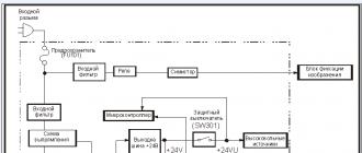
The high-frequency unit contains a conversion stage, input and heterodyne circuits. In receivers of the first and highest classes, as well as in the VHF range, there is a high-frequency amplifier in front of the converter. Checking and adjusting the high-frequency unit can be divided into three stages: 1) checking the generation of the local oscillator; 2) determining the boundaries of the range, often called range stacking; 3) conjugation of input and heterodyne circuits.
Stacking ranges. The tuning of the receiver to the received station is determined by the tuning of the local oscillator loops. Input and UHF circuits only increase the sensitivity and selectivity of the receiver. When tuning it to different stations, the local oscillator frequency should always differ from the received frequency by an amount equal to the intermediate one. To ensure constant sensitivity and range selectivity, it is desirable that this condition be met at all frequencies in the range. However, this ratio of frequencies across the entire range
is perfect. With one-handed tuning, it is difficult to obtain such a pairing. The local oscillator circuits used in broadcasting receivers provide accurate matching of the input and local oscillator settings in each band at only three points. In this case, the deviation from ideal conjugation at the remaining points of the range turns out to be quite acceptable (Fig. 82).
For good sensitivity in the KB range, two points of exact pairing are sufficient. The necessary ratios between the frequencies of the input and heterodyne circuits are achieved by complicating the circuit of the latter. In the heterodyne circuit, in addition to the usual tuning capacitor C1 and the trimmer capacitor C2, there is an additional capacitor C3, called the coupling capacitor (Fig. 83). This capacitor (usually of constant capacitance with a tolerance of ± 5%) is connected in series with a variable capacitor. The inductance of the local oscillator coil is less than the inductance of the coil of the input circuit.
To correctly determine the range limits, remember the following. The frequency of the local oscillator at the beginning of each range is mainly influenced by the change in the capacitance of the tuning capacitor C 2, and at the end of the range - by the change in the position of the core of the inductor L and the capacitance of the coupling capacitor C3. range.
Before tuning the local oscillator circuits, you should find out the sequence of tuning by ranges. In some receiver designs, the CB loop coils are part of the LW loop coils. In this case, the tuning should be started with a medium wavelength, and then tuning with a long wavelength.

Most receivers use a band switching scheme that allows each band to be independently tuned. Therefore, the tuning sequence can be any.
The range is laid using the two-point method, the essence of which is to set the upper frequency limit (the beginning of the range) using a trimmer capacitor, and then the lower frequency (end of the range) by the loop coil core (Fig. 84). But when setting the border of the end of the range, the setting of the beginning of the range is somewhat confused. Therefore, it is necessary to check and adjust the beginning of the range again. This operation is carried out until at both points of the range is reached compliance with the scale.
Conjugation of input and heterodyne circuits. The adjustment is made at two points and checked at the third. The frequencies of the exact mating in receivers with an intermediate frequency of 465 kHz for the middle of the range (f cf) and ends (f 1 and f 2) can be determined by the formulas:

The conjugation of the contours is carried out at the calculated points, which for standard broadcasting bands have the following values

In some models of radio receivers, the pairing frequencies may differ slightly. The lower frequency of exact coupling is usually selected 5 ... 10% above the minimum frequency of the range, and the upper one is 2 ... 5% lower than the maximum. Capacitors of variable capacity allow you to tune the circuits to the exact mating frequency when turning at angles of 20 ... 30, 65 ... 70 and 135 ... 140 °, measured from the position of the minimum capacitance.

To tune tube radios and achieve pairing, the output of the generator signal is connected to the input of the radio receiver (Antenna, Ground jacks) through the all-wave equivalent of the antenna (Fig. 85). Transistor radios with an internal magnetic antenna are tuned !: using a standard field generator, which is a loop antenna connected to the generator through a non-inductive 80 Ohm resistor.

The decadal divider at the end of the generator cable is not connected. The antenna frame is made square with a side of 380 mm from a copper wire with a diameter of 4 ... 5 mm. The radio receiver is located at a distance of 1 m from the antenna, and the axis of the ferrite rod should be perpendicular to the plane of the frame (Fig. 86). The field strength in μV / m at a distance of 1 m from the frame is equal to the product of the readings of the smooth and step attenuators of the generator.
In the KB range, there is no internal magnetic antenna, so the signal from the generator output is fed to the external antenna jack through a capacitor with a capacity of 20 ... 30 pF or to a whip antenna through a blocking capacitor with a capacity of 6.8 ... 10 pF.
The receiver is scaled to the highest frequency of the exact coupling, and the signal generator is adjusted according to the maximum voltage at the output of the receiver. By adjusting the trimmer capacitor (trimmer) of the input circuit and gradually decreasing the generator voltage value, the maximum increase in the output voltage of the receiver is achieved. Thus, the pairing is carried out at this point in the range.
Then the receiver and the generator are tuned to the lowest frequency of the fine conjugation. By rotating the core, the coils of the input circuit achieve the maximum voltage at the output of the receiver. For greater accuracy, this operation is repeated until the maximum voltage at the output of the receiver is reached. After adjusting the contours at the edges of the range, check the accuracy of the pairing at the middle frequency of the range (third point). To reduce the number of oscillator and receiver readjustments, range stacking and loop mating operations are often performed simultaneously.
LW-band setting. The standard signal generator remains connected to the receiver circuitry through the dummy antenna. The lower frequency of the 160 kHz range and the output voltage of 200 ... 500 μV with a modulation depth of 30 ... 50% are set on the generator. The lower coupling frequency is set on the receiver scale (the rotation angle of the KPE rotor is about 160 ... 170 °).
The gain control is moved to the maximum gain position, and the band control to the narrow band position. Then, by rotating the core of the coils of the heterodyne circuit, the voltage at the output of the receiver is maximized. Without changing the frequencies of the generator and receiver, the coils of the UHF circuits (if any) and the input circuits are tuned in the same way until the maximum voltage at the output of the receiver is obtained. At the same time, the value of the generator output voltage is gradually reduced.
Having adjusted the end of the DV range, set the variable capacitor to the position corresponding to the conjugation point at the highest frequency of the range (rotation angle of the KPI 20 ... 30 °), the generator frequency is set equal to 400 kHz, and the output voltage is 200 ... 600 μV. By rotating the tuning capacitors of the circuits, first the local oscillator, and then the UHF and input circuits, the maximum output voltage of the receiver is achieved.
Tuning the loops at the highest frequency of the range changes the tuning at the lowest frequency. To improve the tuning accuracy, the described process must be repeated in the same sequence 2 ... 3 times. When re-adjusting the rotor, the KPI should be put in the previous position, i.e. in the one at which the first adjustment was carried out. Then you need to check the matching accuracy in the middle of the range. The frequency of the exact matching in the middle of the LW range is 280 kHz. Having set this frequency on the generator and the receiver scale, respectively, the accuracy of the calibration and the receiver sensitivity are checked. If there is a dip in the receiver sensitivity in the middle of the range, then it is necessary to change the capacitance of the coupling capacitor, and repeat the tuning process.
The final step is to check if the settings are correct. To do this, first one, then the other end, a test stick is introduced into the tuned circuit, which is an insulating rod (or tube), at one end of which a ferrite rod is fixed, and at the other, made of copper. If the tuning is done correctly, then when approaching the coil field of the loop of either end of the test stick, the signal at the output of the receiver should decrease. Otherwise, one of the ends of the stick will decrease the signal, and the other will increase it. After the LH band is tuned, you can adjust the MH and HF bands in the same way. However, as already noted, in the HF band, it is sufficient to perform pairing at two points: at the lower and upper frequencies of the range. In most radios, the KB band is divided into several sub-bands. In this case, the exact pairing frequencies have the following meanings!

Features of setting the HF band. When tuning the HF range, the signal from the generator can be heard in two places on the tuning scale. One signal is the main one, and the second is the so-called mirror signal. This is explained by the fact that in the HF band the mirror signal is suppressed much worse, and therefore it can be confused with the Main signal. Let us explain this with an example. A voltage with a frequency of 12 100 kHz is applied to the input of the receiver, that is, the beginning of the HF range. In order to obtain a frequency equal to the intermediate frequency at the output of the frequency converter, i.e. 465 kHz, it is necessary to tune the local oscillator to a frequency equal to 12 565 kHz. When the local oscillator is tuned to a frequency of 465 kHz below the received signal, ie 11 635 kHz, an intermediate frequency voltage is also provided at the output of the converter. Thus, the intermediate frequency in the receiver will be obtained at two frequencies, the local oscillator, of which one is higher than the signal frequency by the value of the intermediate frequency (correct), and the other is lower (incorrect). As a percentage, the difference between correct and incorrect LO frequencies is very small.
Therefore, when setting the HF range, one should choose from two local oscillator settings the one that is obtained with a smaller capacitor capacitor of the circuit or with a more turned-out coil core. The correctness of the local oscillator setting is checked at a constant frequency, the generator signal. When the capacitance (or inductance) of the local oscillator circuit is increased, the signal should be heard in one more place on the receiver scale. You can also check the correctness of the local oscillator setting while keeping the receiver setting unchanged. When changing the frequency, the signal of the generator to a frequency equal to two intermediate ones, i.e., to 930 kHz, the signal must also be heard. A higher frequency in this case is called a mirror image, and a lower frequency signal is the main one.
Tuning the antenna filter. Tuning the high frequency unit begins with tuning the antenna filter. For this, the output signal of the generator is connected to the input of the receiver through the antenna equivalent. On the frequency scale of the generator, the frequency is set to 465 kHz and the modulation depth is 30 ... 50 %.The output voltage of the generator should be such that the output meter connected to monitor the output voltage of the receiver shows a voltage of about 0.5 ... 1 V. set to the DV position, and the adjustment arrow - to a frequency of 408 kHz. Rotating the core of the antenna filter circuit, achieve the minimum voltage at the output of the receiver, while the output voltage of the generator is increased as the signal weakened.
After finishing the adjustment, all the tuned cores of the loop coils, the positions of the magnetic antenna coils must be fixed.
Setting up a transistor receiver, in principle, differs little from setting up a tube receiver. After making sure that the bass amplifier is fixed and the tubes or transistors of the receiver are working in normal modes, they start tuning the circuits. The tuning begins with the detector stage, then proceeds to the IF amplifier, local oscillator and input circuits.
It is best to tune the contours with a high frequency generator. If it is not there, then you can tune in by ear, according to the received radio stations. In this case, it may be necessary to only have an avometer of any type (TT-1, VK7-1) and another receiver, the intermediate frequency of which is equal to the intermediate frequency of the tuned receiver, but sometimes it is tuned without any instruments. The autometer serves as an indicator of the output signal during setup.
When adjusting the circuits of the IF amplifier in a tube receiver, when an RF generator and a tube voltmeter are used for this purpose, the latter must not be connected to the lamp grid, since the input capacitance of the voltmeter is added to the capacitance of the grid circuit. When adjusting the circuits, a voltmeter should be connected to the anode of the next lamp. In this case, the circuit in the anode circuit of this lamp must be shunted with a resistor with a resistance of the order of 500 - 1000 Ohm.
Having finished setting up the IF gain path, they begin to set up the local oscillator and the RF amplifier. If the receiver has several bands, then the tuning starts with the KB band, and then proceeds to tuning.
CB and LW circuits. Short-wave coils (and sometimes medium-wave ones), unlike long-wave ones, usually do not have cores; they are most often wound on cylindrical (and sometimes on ribbed) frames. The change in the inductance of such coils is carried out when tuning the circuits, shifting or moving apart the turns of the coils.
In order to determine whether the turns should be shifted or moved apart in a given circuit, it is necessary to bring inside the coil or bring a piece of ferrite and a brass (or copper) rod alternately to it. It is even more convenient to perform this operation if, instead of a separate piece of ferrite and a brass rod, use a special combined indicator stick, at one end of which magnetite (ferrite) is fixed, and at the other end - a brass rod.
The inductance of the coil of the RF amplifier circuit should be increased if, at the mating points of the circuits, the volume of the signal at the output of the receiver increases with the introduction of ferrite into the coil and decreases with the introduction of a brass rod, and vice versa, the inductance should be reduced if the volume increases with the introduction of a brass rod and decreases with the introduction of ferrite. If the circuit is configured correctly, the attenuation of the signal volume at the mating points occurs when both ferrite and brass rods are inserted.
The CB and LW contours are tuned in the same order. The change in the inductance of the loop coil at the mating points is made in these ranges by the corresponding adjustment of the ferrite core.
When making homemade loop coils, it is recommended to wind several obviously extra turns. If, when tuning the circuits, it turns out that the inductance of the loop coil is insufficient, winding up the turns on the finished coil will be much more difficult than winding up the extra turns during the tuning itself.
The factory receiver can be used to make it easier to set up the contours and calibrate the scale. Comparing the angles of rotation of the axes of the variable capacitors of the tuned receiver and the factory receiver (if the blocks are the same) or the position of the scale pointers, they determine in which direction the loop setting should be shifted. If the station on the scale of the tuned receiver is closer to the beginning of the scale than that of the factory one, then the capacity of the tuning capacitor of the local oscillator circuit should be reduced, and vice versa, if closer to the middle of the scale, it should be increased.
Methods for checking the local oscillator in a tube receiver. You can check whether the local oscillator is working in a tube receiver in different ways: using a voltmeter, an optical tuning indicator, etc.
When using a voltmeter, it is connected in parallel with a resistor in the anode circuit of the local oscillator. If the closure of the capacitor plates in the local oscillator circuit causes an increase in the voltmeter readings, then the local oscillator works. The voltmeter must have a resistance of at least 1000 Ohm / V and be set to a measurement limit of 100 - 150 V.
Checking the operability of the local oscillator with an optical tuning indicator (6E5C lamp) is also simple. For this, the control grid of the local oscillator lamp is connected with a short conductor to the grid of the 6E5C lamp through a resistor with a resistance of 0.5 - 2 MΩ. The dark sector of the tuning indicator should be completely closed during normal operation of the local oscillator. By the change in the dark sector of the 6E5C lamp when you rotate the receiver tuning knob, you can judge about the change in the generator voltage amplitude in different parts of the range. If the unevenness of the amplitude is observed within significant limits, a more uniform generation over the range can be achieved by selecting the number of turns of the coupling coil.
The operation of the local oscillator of the transistor receiver is checked by measuring the voltage at the load of the local oscillator (most often at the emitter of the transistor of a frequency converter or mixer). The local oscillator voltage, at which the frequency conversion is most effective, lies in the range of 80 - 150 mV on all ranges. The voltage across the load is measured with a lamp voltmeter (VZ-2A, VZ-3, etc.). When the local oscillator circuit is closed, its oscillations break down, which can be noted by measuring the voltage across its load.
Sometimes self-excitation can be eliminated in very simple ways. So, in order to eliminate self-excitation in the IF amplification stage, a 100 - 150 Ohm resistor can be connected to the control grid of the lamp of this stage. The amplification of the intermediate frequency voltage in the stage will decrease slightly, since only a small part of the input signal voltage is lost on the resistance.
In transistor receivers, self-excitation can be observed if the battery of cells or accumulators is discharged. In this case, the battery should be replaced and the batteries charged.
In some cases, self-excitation in the receiver and TV can be eliminated by such measures as transferring the grounding of individual circuit elements, reworking the installation, etc. The effectiveness of the measures taken to combat self-excitation can often be assessed in the following way.
Rice. 25. To an explanation of the way to eliminate self-excitation in transistor reflex receivers
The receiver or TV set is connected to a regulated power source (that is, to a source whose voltage supplied to the anode circuits can be varied over a wide range), and a lamp voltmeter or other dial indicator is turned on at the output of the receiver. Since at the moment of self-excitation the voltage at the output of the receiver changes sharply, the deviation of the indicator arrow makes it easy to note this. The voltage taken from the source is controlled by a voltmeter.
If self-excitation occurs at the rated voltage, then the supply voltage is reduced to a value at which generation stops. Then they take certain measures against self-excitation and increase the voltage until generation occurs, marking it with a voltmeter. In the case of successful measures, the self-excitation threshold should increase significantly.
In transistor reflex receivers, self-excitation can occur due to the unfortunate location of the high-frequency transformer (or choke) relative to the magnetic antenna. Such self-excitation can be eliminated by using a short-circuited coil of copper wire with a diameter of 0.6 - 1.0 mm (Fig. 25). A U-shaped wire bracket is passed through a hole in the board, bent from below, twisted and soldered to the common wire of the receiver. The bracket can serve as a fastening element for the transformer. If the transformer winding is evenly wound on the ferrite ring, then the appropriate orientation of the short-circuited turn relative to other ferrite parts is not required.
Why the receiver "howls" on the KB band. It can often be observed that a superheterodyne receiver, when receiving a broadcasting station at short wavelengths, begins to "howl" with a small detuning. However, if the receiver is tuned more precisely to the station being received, the reception will return to normal.
The reason for the “howling” when the receiver is operating at short wavelengths is the acoustic coupling between the receiver loudspeaker and the tuning capacitor bank.
This generation can be eliminated by improving the damping of the tuner, as well as by reducing the various available methods of acoustic feedback - changing the way the loudspeaker is mounted, etc.
Tuning the IF amplifier with another receiver. At the beginning of this section, a method was described for tuning a radio receiver using the simplest devices. In the absence of such devices, the tuning of radio receivers is usually performed by ear, without devices. However, it should be said right away that this method does not provide sufficient tuning accuracy and can only be used as a last resort.
To tune the IF amplifier loops, instead of a standard signal generator, you can use a different receiver with an IF equal to the IF of the receiver you are tuning. -With a tuned tube receiver, the AGC wire going from the diode to the control grids of the adjustable lamps must be disconnected from the diode during tuning and connected to the chassis. If this is not done, then the AGC system will make it difficult to fine-tune the bandpass filters. In addition, when tuning the IF amplifier, it is necessary to disrupt the oscillations of the local oscillator by blocking its circuit with a capacitor with a capacity of 0.25 - 0.5 μF.
The auxiliary receiver used in this case does not need to undergo any significant alterations. To set up, you need only a few additional parts: a variable resistor (0.5 - 1 MΩ), two constant capacitors and two or three constant resistance resistors.
Tuning the amplifier circuits. The receiver IF is produced as follows. The auxiliary receiver is pre-tuned to one of the local long- or medium-wave stations. Further, the common wires or chassis of both receivers are connected to each other, and the wire going in the tube receiver to the control grid of the lamp of the first IF gain stage of the auxiliary receiver is disconnected and connected to the control grid of the lamp of the corresponding IF amplifier stage of the tunable receiver. In the case of tuning a transistor receiver, the IF signal through capacitors with a capacity of 500 - 1000 pF is fed alternately to the bases of the transistors of the corresponding stages of the IF amplifier.
Then both receivers turn on again, however, in order to avoid interference during tuning, the low-frequency part of the auxiliary, as well as the local oscillator of the tuned receiver, should be turned off (in tube receivers, removing the lamps of the LF amplifier and local oscillator, respectively).
When tuning the cascades of the IF amplifier of a transistor receiver, its local oscillator should be turned off by setting a jumper in the local oscillator circuit.
After that, by applying the intermediate frequency signal from the auxiliary receiver to the input of the tunable IF amplifier and smoothly adjusting the tuning of the IF circuits of the latter, they achieve audibility of the station to which the auxiliary receiver is tuned. Then they continue to tune each circuit separately (to the maximum signal level), and the tuning is best done using a dial gauge connected to the output of the bass amplifier, or by an optical indicator (6E5C lamp or the like).
Start tuning from the last IF loop; the signal is fed to the base of the corresponding transistor or directly to the grid of the lamp, in the anode circuit of which the tunable circuit is included.
If the adjustment is carried out not by the optical indicator, but by the sound volume, then the volume level is recommended to be set to the minimum, since the human ear is more sensitive to changes in the volume level with weak sounds.
About tuning the receiver to radio stations. Tuning of a superheterodyne receiver - tube or transistor - for received stations without using an auxiliary receiver is usually started on the KB band. By adjusting the IF contours to the maximum of noise and turning the tuning knob, the receiver is installed on any of the audible stations. If it is possible to receive such a station, then they immediately begin to adjust the IF circuits, achieving maximum audibility (the tuning begins with the last IF circuit). Then they tune the heterodyne and input circuits, first on short, then on medium and long waves. It should be noted that setting up receivers using this method is complex, time consuming and requires experience and skills.
The 6E5C lamp is an indicator when setting up. It is not recommended to adjust the receiver contours in terms of sound volume, as already mentioned, especially if a high output volume level is set. The sensitivity of the human ear to changes in signal level in response to loud sounds is very low. Therefore, if you still have to tune the receiver by sound, then the volume should be set to a low level, or, what is better, use an optical tuning indicator - a 6E5C lamp or another similar one.
When tuning superheterodyne receivers according to received stations and using the 6E5C lamp as an indicator of tuning accuracy, it is more convenient to adjust the contours at such an input signal level at which the dark sector of this lamp narrows to 1 - 2 mm.
To regulate the signal voltage at the input of the receiver, parallel to the antenna coil, you can connect, for example, a variable resistance resistor, the value of which, depending on the sensitivity of the receiver, can be selected in the range from 2 to 10 kOhm.
How to find a faulty stage in an RF amplifier. When adjusting or repairing a receiver, a cascade in which there is a malfunction can be detected using an antenna, alternately connecting it to the bases of transistors or to the grids of amplifier lamps and determining by ear by noise whether there are malfunctions in these cascades.
This method is convenient to use in cases where there are several RF amplification stages.
An antenna in the form of a piece of wire can also be used when checking the IF and RF amplification stages in TVs. Since short-wave stations often work at frequencies close to the intermediate frequency of televisions, listening to these stations will indicate the health of the audio channel,
|
|
So, observing reasonable care, we open the device. We look at what the frequency control knob is connected to. It can be a variometer (a metal, several centimeters gizmo, usually two or one double, with longitudinal holes into which a pair of cores slide in or out.) This option has often been used before. Until I write about it. () And it may be - a plastic cube a few centimeters in size (2 ... 3). Several capacitors live in it, which change their capacity at our whim. (There is also a method for tuning with varicaps. In this case, the tuning control is very similar to the volume control. I have never seen such an option).
2. LET'S FIND A HETERODY COIL AND CONDENSERS CONNECTED TO IT.
So, you have KPE! We proceed further. We are looking for copper coils around it (yellow, brown spirals of several turns. Usually they are not even, but wrinkled and knocked down. And this is correct, they are tuned in this way.). We can see one, two, three or more coils. Don't be alarmed. Everything is very simple. We turn on your device disassembled (do not forget to connect the antenna longer) and tune it to any radio station (better not to the loudest one). After that, touch it with a metal screwdriver or just with your finger (contact is optional, just slide something near the coil. The response of the receiver will be different. The signal may become louder or there may be interference, but the coil we are looking for will give the strongest effect. several stations and the reception will be completely disrupted. So this is what a HETERODY coil. The frequency of the local oscillator is determined by a circuit consisting of this very coil and capacitors connected in parallel to it. There are several of them - one of them is in the CPE and manages the frequency tuning (we catch different stations), the second is also located in the KPE cube, or rather on its surface. Two or four small screws on the back surface of the KPE (usually facing us) are two or four trimming capacitors. One of them is used to adjust the local oscillator. Usually these capacitors consist of two plates that slide over each other when the screw rotates. the ny plate is exactly above the bottom, then capacity is maximum... Use a screwdriver to touch these screws. Move them back and forth a few (as little) degrees as possible. You can mark their starting position with a marker to insure against trouble. Which one affects the setting? Found it? We will need it in the near future.
3. Once again, LET'S DETERMINE WHERE WE ARE REBUILDING AND ACTING.
What range is in your receiver and what you need. Lowering the frequency or raising it? To lower the frequency, it is enough to add 1 ... 2 turns to the heterodyne coil. As a rule, it contains 5 ... 10 turns. Take a piece of bare tinned wire (for example, a lead from some long-legged element) and put on a small prosthesis. After this build-up, the coil must be adjusted. We turn on the receiver and catch some station. No stations? Nonsense, let's take a longer antenna and rotate the tuning. Here, something is caught. What is it. We'll have to wait until they say, or take another receiver and catch the same thing. See how this station is located. Whether at the end of the range. Need to move it even lower? Easily. Let's move the turns of the coil more tightly. Let's catch this station again. Now good? It only catches badly (the antenna needs a long one). Right. Now we will find the antenna coil. She is somewhere near. The wires from the KPI must be suitable for it. Let's try turning on the receiver, insert it into it, or just bring some ferrite core to it (you can take the DM choke by removing the winding from it). Has the volume of the reception increased? Exactly, this is it. To reduce the frequency, it is necessary to increase the coil by 2 ... 3 turns. A piece of hard copper wire will do. You can simply replace the old coils with new ones containing 20% more turns. The turns of these coils should not be tight. By changing the stretching of the coil and bending it, we change the inductance. The tighter the coil is wound and the more turns in it, the higher its inductance and below will be the working range. Do not forget that the actual inductance of the loop is higher than the inductance of a single coil, since it is added to the inductance of the conductors that make up the loop.
For the best reception of the radio signal, it is necessary that the difference in the resonant frequencies of the heterodyne and antenna circuits is 10.7 MHz - this is the frequency of the intermediate frequency filter. This is called correct mating of the input and heterodyne circuits. How to provide it? We read on.
SETTING (PAIRING) INPUT AND HETERODY CIRCUITS.
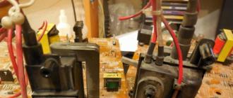
FIG. 1. High-frequency part of the VHF-FM radio receiver board. It is clearly seen that the input circuit trimmer (CA-P) is set to the minimum capacitance position (as opposed to the CG-P heterodyne trimmer). Accuracy of setting the rotors of the trimmer capacitors is 10 degrees.
The local oscillator (LG) coil has a large hole in the winding that reduces its inductance. This hole appeared during the setup process.
Another coil is visible at the top of the photo. This is the input antenna circuit. It is broadband and is not tunable. The telescopic antenna is connected to this very circuit (via a transition capacitor). The purpose of this circuit is to remove coarse interference at frequencies much lower than the operating ones.
AND ANOTHER ACTION, BECAUSE WE ARE ALREADY HERE.
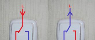
Tune in to your favorite station, then shorten the antenna to a minimum when there is already interference and adjust the IF filter, which looks like a metal square with a purple circle (in the middle left of the photo). Fine tuning this circuit is very important for clear and loud reception. Accuracy of installation of the slot is 10 degrees.
You will need only one microcircuit to build a simple and complete FM receiver that can receive radio stations in the 75-120 MHz range. The FM receiver contains a minimum of parts, and its tuning, after assembly, is minimized. It also has good sensitivity for receiving VHF FM radio stations.
All this thanks to the Philips TDA7000 microcircuit, which you can buy without any problems on our beloved Ali Express -.
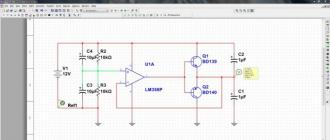
Receiver circuit
Here is the receiver circuit itself. Two more microcircuits are added to it, so that at the end you get a completely finished device. Let's start looking at the diagram from right to left. A low-frequency amplifier for a small dynamic head is assembled on the LM386 running microcircuit, which has already become a classic. Here, I think, everything is clear. A variable resistor adjusts the volume of the receiver. Further, a stabilizer 7805 is added above, which converts and stabilizes the supply voltage up to 5 V. Which is needed to power the microcircuit of the receiver itself. And finally, the receiver itself is assembled on the TDA7000. Both coils contain 4.5 turns of PEV-2 0.5 wire with a winding diameter of 5 mm. The second coil is wound on a frame with a ferrite trimmer. The receiver is tuned to the frequency with a variable resistor. The voltage from which goes to the varicap, which in turn changes its capacity.If desired, the varicap and electronic control can be abandoned. And the frequency can be tuned either with a tuning core or with a variable capacitor.
FM receiver board
I drew the mounting plate for the receiver in such a way as not to check the holes in it, but to solder everything from the top as with SMD components.Placing elements on the board

Used the classic LUT technology for the production of the board.


Printed, warmed up with an iron, etched and washed off the toner.


Soldered all the elements.