Hello everyone. Today I will tell you in detail and show you how to change micro-USB connectors and other little things on your knees ”, ie at home, without special skills and special professional expensive priblud and substances. Just armed with inspiration, always helping out with optimism, ingenuity, perseverance, patience and enough time.
Yesterday they brought me a smartphone for repair Lumia Denim 630 with a faulty power socket, with the words: Charging shows - but does not want to charge! " The smartphone looked monolithic, without screws and latches, I thought: Well, there you go! Now I have to warm it up with a hair dryer! ", Although after tinkering it turned out that it can be opened easily, since the insides lie in the lid, a trough" which is easily separated (on the internal latches). Those. the developers of Nokia have thought out everything, according to the military ”. For this they get a delicious like from me!
The socket externally turned out to be in good condition, no cracks in the soldering were found, which means how often the malfunction was hidden in the erased contacts inside the connector. I decided to boldly change to a new one. After the repair, I disassembled the old socket, and indeed the contacts were in mud, in oil felt "and looked worn out. I forgot to take a picture, but in general, what kind of connectors are killed, look at the photo attached to the article.
A sure sign that the nest needs to be changed
I bought nests on Ali Express, in a handful of about 100 pieces, 10 types, which is convenient.

Set of micro-usb jacks
I picked up a suitable one, but not identical, which had to be modified and filed.

The nest has to be adjusted
As it turned out later, given the almost outward similarity of the seat, the gilded contacts did not fit in height, that is, they hovered "over the board!" Take note!

Fitted the socket, but did not notice the discrepancy to the original
I had to pick up the nest on a new one, file it again, adjust it, since there was no needed one.
The nest has to be adjusted
When fitting, a slight distortion of the nest was revealed, i.e. opening the fastening locks of the nest, which had to be put in place, soldered and slightly adjusted to the lid of the smart with a sharp knife.

Socket fitted
And all because the nests ordered in bulk are cheap, which means they are simpler, made of not very durable metal, in comparison with the native nests. Native nests are usually very expensive, made soundly, reliably, but you can't find enough of them for any occasion. Ordering relatives in China and tediously waiting is problematic. I decided to take apart the old nest, weighing all the pros and cons, and comparing the price tags in Ali.
For desoldering, I use a special hot air gun, although you can completely do with a building hair dryer, while being vigilant and attentive so as not to fry ”truncated around.

Soldering hair dryer
Be sure to cover all plastic parts, capacitors with pastry foil or chocolate, otherwise they may melt! Then kirdyk to your smart can come to the offensive suddenly and without origin! 🙂 Ie first, in a circular motion, warm up the entire board, so that it does not lead, with a propeller "from the temperature difference, and then in a circular motion you heat the nest itself (about 300 degrees, check with the temperature sensor of a multimeter or by using your intuition and fingers). Before warming up, it is advisable to simply solder the socket with ordinary solder with flux or rosin (mix your tin with the factory tin, thereby making it easier to solder), since the factory solder on the board is often lead-free, which causes problems with soldering the socket.

By the way, for the convenience of work, I completely manage with an ordinary pastry silicone mat, as professional roads.

My soldering mat
It keeps high temperatures and does not slip on it, i.e. a practical and appropriate thing. I also use a special board holder with crocodiles ", with which I conveniently fix the board.

PCB holder
The rug and holder were purchased on Ali. In general, you can do without them, including the smart one. 🙂
After desoldering, I use a braid moistened with flux or rosin, leaning it against with a soldering iron and guiding them along the tracks and holes with tin, also pre-lubricated with flux.

braid for solder removal
As a result, the braid absorbs all interfering solder, leaving everything around clean (cool idea!). The only thing to keep in mind is, do not strip the tracks and contact dimes with a braid! This also takes place! Be careful and take your time!
I forgot to say that soldering out the socket with a soldering iron is problematic and risky. Of course, with good experience, you can evaporate and subtly - with the help of one large drop of solder, covering the entire socket with it and looking so as not to stagger "and not stick adjacent parts to your mega-drop, etc. But still it is skillfully done by people with a full hand and experience. As an option, in the workshops earlier (when there were no hair dryers, in the USSR), they made (bought) special nozzles-stings for the necessary connectors and sockets, which made it possible to supply heat to all the required areas at a time and easily evaporate. It was an excursion, but for you it is still easier with a hot air gun.

Special tips
Ideally, a special microscope is successfully used in workshops for soldering small parts. I use magnifying glasses, since I still can't afford a good microscope, and a cheap one is just a waste of money.

Illuminated magnifying glasses
I also use a set of clock screwdrivers for disassembly and assembly, and I also use them with pleasure as convenient small cleaners (from rosin on the board), picks, pushers, pusher legs of elements, etc. I got it at the nearest hardware store, for a symbolic amount.

Cheap watch screwdriver set
The varieties of tweezers purchased by me in Ali and in Fix-price help a lot. " In an important case, the female cosmetic tweezers can be useful. 🙂
The tip of your family's forty-watt soldering iron will need to be sharpened at an acute angle and with a slightly rounded end in order to creep up to the socket legs neatly and effectively and painlessly for neighboring radioelements.

Soldering iron tip sharpening
Or just wind the copper wire around the tip and use it as a thin tip, in common people: "Quickly, a mini-soldering iron!"

Mini soldering iron
It is advisable to buy a cheap power regulator for lamps, with which you will regulate the temperature of the sting so that the rosin on the sting does not quickly turn into carbon deposits, so as not to overheat the conductive tracks and so that they do not fly off.

Lamp power regulator
You can, of course, without a power regulator, but then you have to solder with short touches so as not to overheat the tracks and boringly often cleaning the sting from black rosin oxides. And again - and this is the art of the possible, on the verge of risk. Decide for yourself.
Let's continue. Before soldering, I washed off the used flux from the board with a toothbrush soaked in alcohol (you can also use vodka, but it is not quite suitable because of oils), rustling it towards the edges of the board so that the old flux does not smear on the board, flew off the board and led to corrosion of adjacent copper tracks. In general, this largely applies to almost all fluxes, no-clean and neutral, it also applies to rosin, so they are all to one degree or another aggressive and to one degree or another, their evaporation is harmful to health (ventilate the room!). Therefore, it is advisable to wash off with alcohol, washes, etc., and scrape off the rosin and rinse with alcohol (under the rosin, it also corrodes the tracks!). Then I looked to see if the contact pads were clean and soldered (there should not be a lot of solder, that is, no hills, just soldering so that the socket lay flat and soldered) greased the rations with flux (see the flux in the photo), put it down, aiming " exactly on the seats, so that the socket then coincides with the back cover and soldered, periodically replenishing the tip with solder. Well, or if your solder is in the form of a thin wire, bring it to the soldering point with a tip. If you only have rosin, then just pick up solder with a sting, then soak it in rosin and quickly until the rosin on the sting turns into a nasty black mass due to overheating, solder the necessary contact dimes to the socket.
After that, be sure to check how you soldered, whether everything looks beautiful, whether something sticks out, whether there is a so-called. , snot "between the contact pads, as this can cause a short circuit and is fraught with more serious breakdown of the device. Use a little braid, if the sting cannot be removed with a sting, it will take away excess solder, and the tin will squeeze out under the leg of the socket. If, nevertheless, a little remains, then grease the place with rosin and lightly tear off the remains of tin between the contacts with a sting. But do not overdo it, the solder should be in the form of a sufficient droplet covering the contact for a firm contact. Do not feel sorry for the flux (rosin) so that the soldering is electrically conductive (and not the so-called "cold" or, dry "soldering, not conductive).
Now, partially, without screws, we assemble the smartphone, connect the cables, turn on, check for operability, if everything is fine, charging is in progress, the battery shows that it is accumulating charge, then we finally assemble by screwing and closing the rear decorative cover.
For clarity of the process of replacing the nest, I cut you gifs from the video of the professional's work. Watch and listen.
They brought a Chinese tablet with the words "does not charge."
Plugging the charger into the connector, I immediately realized that the connector was simply torn from the board. The most frequent breakdown. Well, let's start dissecting our client. To do this, with a tenacious gaze, we peer around the perimeter of the tablet and look for the screws that hold it together. Without thinking for a long time, we unscrew these screws
.JPG)
.JPG)
Voila!
.JPG)
I don't see any point in disassembling where the memory chip is located, percentages and other various mikruhi, since basically repairing the tablet involves replacing the touchscreen, display and connectors.
And here is the micro-USB charging connector. We need to replace it.
.JPG)
Now we need to get the board. We unscrew all the bolts that hold it. We also remove all the cables that go to the board. To do this, lift the clasp with your finger up
.JPG)
If the wires interfere, we also solder them. I only soldered the battery. Since our connector is torn out with meat and is broken, we immediately throw it away. We begin to clean the seat for the new connector. To remove the solder in the through holes, we need a low-melting Wood or Rose alloy. To begin with, we abundantly tin the holes with this alloy, do not forget to also smear with gel flux. We heat the through hole together with the alloy with a soldering iron and then abruptly with the help of a desoldering pump pull out all the solder from the hole
.JPG)
I took the rubber tip for the desoldering pump from an old CD-shnoy car radio. I don't know what they are doing there, but there are even two of them.
Now we remove all excess solder from the contact pads (patches) using copper braid and a heated soldering iron
.JPG)
After this procedure, on the signal contacts using a soldering iron, solder and gel flux, we need to leave a bump of solder on each contact pad. Although this photo is from a different repair, the example should look something like this:

Now we take a new connector and smear its contacts with LTI-120 flux
.JPG)
.JPG)
.JPG)
A little about the connectors ... There are a lot of these micro USB connectors! Almost every manufacturer of tablets, phones and other bullshit uses their micro USB connectors. But I still found a way out ;-). I went to Aliexpress and bought myself a whole set at once. Here link... But now I have all kinds of connectors for Chinese phones and tablets ;-)
As soon as the connector is anointed, we tin-coat its contacts with solder. The main thing here is not to overdo it, otherwise the connector will not fit into the through holes on the board.
The rest is simple. We insert the connector, seal the through contacts on the other side, and then liberally grease the signal contacts of the connector with gel flux and press each contact with the tip of the sting. (Sorry, it is inconvenient to take a photo, since I only have two hands, and there was no one nearby)
.JPG)
and then we clean the connector from poop and carbon deposits
.JPG)
We do everything as it was and check the tablet:
.JPG)
Charging is in progress. This completes the tablet repair.
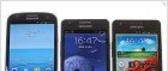
Most modern mobile phones, smartphones, tablets and other wearable gadgets support charging via the USB mini-USB or micro-USB jack. True, it is still far from a single standard, and each company is trying to make the pinout in its own way. Probably to buy the charger from her. Well at least the YUSB plug and socket were made standard, as well as the supply voltage of 5 volts. So having any charger adapter, you can theoretically charge any smartphone. How? and read on.

Pinout of USB connectors for Nokia, Philips, LG, Samsung, HTC
The brands Nokia, Philips, LG, Samsung, HTC and many other phones recognize the charger only if the Data + and Data- contacts (2nd and 3rd) are short-circuited. You can short-circuit them in the USB_AF socket of the charger and easily charge your phone via a standard data cable.

Pinout of USB connectors on the plug
If the charger already has an output cord (instead of an output jack), and you need to solder a mini-USB or micro-USB plug to it, then you do not need to connect 2 and 3 pins in the mini / micro USB itself. In this case, you solder plus to 1 contact, and minus to the 5th (last).

Pinout USB connectors for Iphone
For iPhones, Data + (2) and Data- (3) contacts must be connected to GND (4) through 50 kOhm resistors, and to + 5V through 75 kOhm resistors.

Samsung Galaxy charging connector pinout
To charge the Samsung Galaxy in the USB micro-BM plug, a 200 kΩ resistor must be installed between pins 4 and 5 and a jumper between pins 2 and 3.

Pinout of USB connectors for Garmin navigator
Your Garmin Navigator requires a dedicated data cable to power or charge. Just to power the navigator through the cable, you need to short-circuit 4 and 5 contacts in the mini-USB plug. For recharging, you need to connect 4 and 5 contacts through an 18 kΩ resistor.

Pinout schemes for charging tablets
Almost any tablet computer requires a large current to charge - 2 times more than a smartphone, and charging through the mini / micro-USB socket in many tablets is simply not provided by the manufacturer. After all, even USB 3.0 will not give more than 0.9 amperes. Therefore, a separate socket is placed (often of a round type). But it can also be adapted to a powerful YUSB power source if you solder such an adapter.

Samsung Galaxy Tab charging socket pinout
To properly charge the Samsung Galaxy Tab tablet, a different scheme is recommended: two resistors: 33 kΩ between +5 and the D-D + jumper; 10 kΩ between GND and the D-D + jumper.

Charging port pinout
Here are some voltage diagrams on the USB pins, indicating the value of the resistors that allow these voltages to be obtained. Where a resistance of 200 ohms is indicated, a jumper must be installed, the resistance of which should not exceed this value.
Charger Port Classification
- SDP (Standard Downstream Ports) - Data exchange and charging, allows current up to 0.5 A.
- CDP (Charging Downstream Ports) - data exchange and charging, allows current up to 1.5 A; hardware recognition of the port type (enumeration) is performed before the gadget connects data lines (D- and D +) to its USB transceiver.
- DCP (Dedicated Charging Ports) - Charging only, allows current up to 1.5 A.
- ACA (Accessory Charger Adapter) - PD-OTG operation is declared in Host mode (with connection to PD peripherals - USB-Hub, mouse, keyboard, HDD and with the possibility of additional power supply), for some devices - with the ability to charge PD during an OTG session ...
How to remake a plug with your own hands
 Now you have a pinout diagram for all popular smartphones and tablets, so if you have the skill to work with a soldering iron, there will be no problems with converting any standard USB connector to the type you need for your device. Any standard charging, which is based on the use of USB, provides for the use of only two wires - this is + 5V and a common (negative) contact.
Just take any charging adapter 220V / 5V, cut off the USB connector from it. The cut end is completely free of the shield while the other four wires are stripped and tinned. Now we take a cable with a USB connector of the required type, after which we also cut off the excess from it and carry out the same procedure. Now it remains just to solder the wires together according to the diagram, after which the connection is isolated each separately. The resulting case is wrapped from above with electrical tape or tape. You can fill it with hot glue - also a normal option.
Bonus: all other connectors (sockets) for mobile phones and their pinouts are available in a single large table -.
USB (Universal Serial Bus - "universal serial bus") - serial data interface for medium speed and low speed peripheral devices. A 4-wire cable is used for connection, with two wires used for receiving and transmitting data, and 2 wires for powering the peripheral device. With built-in uSB power lines allows you to connect peripherals without their own power supply.
USB basics
USB cable consists of 4 copper conductors - 2 power conductors and 2 data conductors in twisted pair, and a grounded braid (shield).USB cables have physically different tips "to the device" and "to the host". It is possible to implement a USB device without a cable, with a tip “to the host” built into the case. One-piece integration of the cable into the device is also possible(e.g. USB keyboard, Webcam, USB mouse)although the standard prohibits this for full and high speed devices.
USB bus strictly oriented, that is, it has the concept of a "master device" (a host, also known as a USB controller, is usually built into the south bridge microcircuit on the motherboard) and "peripheral devices".
Devices can be powered by +5 V from the bus, but they can also require an external power supply. The standby mode for devices and splitters is also supported by a command from the bus with the removal of the main power supply while maintaining the standby power and turning on by a command from the bus.
USB supportsHot plugging and unplugging of devices... This is possible due to the increase in the length of the conductor of the grounding contact in relation to the signal. When connected uSB connector the first to close grounding contacts, the potentials of the cases of the two devices become equal, and further connection of the signal conductors does not lead to overvoltages, even if the devices are powered from different phases of the three-phase power network.
At the logical level, a USB device supports data transmission and reception transactions. Each package of each transaction contains a number endpoint on the device. When a device is connected, drivers in the OS kernel read a list of endpoints from the device and create control data structures to communicate with each device endpoint. The collection of endpoint and data structures in the OS kernel is called pipe.
Endpoints, and hence channels, belong to one of 4 classes:
- in-line (bulk),
- manager (control),
- isochronous (isoch),
- interrupt
Low speed devices such as a mouse may not have isochronous and streaming channels.
Control channel intended for exchange with the device in short question-answer packets. Any device has control channel 0, which allows OS software to read brief information about the device, including the manufacturer and model codes used to select the driver, and a list of other endpoints.
Interrupt channel allows you to deliver short packets in both directions, without receiving a response / confirmation, but with a guarantee of delivery time - the packet will be delivered no later than N milliseconds. For example, it is used in input devices (keyboards, mice, or joysticks).
Isochronous channel allows you to deliver packages without a guarantee of delivery and without replies / confirmations, but with a guaranteed delivery speed of N packets per bus period (1 KHz for low and full speed, 8 KHz for high speed). Used to transmit audio and video information.
Streaming channel provides a guarantee of delivery of each packet, supports automatic suspension of data transmission due to the device's unwillingness (buffer overflow or underflow), but does not guarantee the speed and delay of delivery. Used, for example, in printers and scanners.
Bus time divided into periods, at the beginning of the period the controller transmits a packet "start of period" to the entire bus. Further, during the period, interrupt packets are transmitted, then isochronous in the required amount, in the remaining time in the period, control packets are transmitted and, last of all, streaming ones.
Active side of the bus there is always a controller, the transfer of a data packet from a device to a controller is implemented as a short question of the controller and a long, containing data, response of the device. The packet movement schedule for each bus period is created by a joint effort of the controller hardware and driver software, for this many controllers use DMA Direct Memory Access (Direct Memory Access) - the mode of data exchange between devices or between the device and the main memory, without the participation of the Central Processor (CPU). As a result, the transfer rate increases as no data is sent to and from the CPU.
The packet size for an endpoint is a constant hardwired into the device's endpoint table and cannot be changed. It is selected by the device developer from among those supported by the USB standard.
USB Specifications
Features, advantages and disadvantages of USB:
- High speed of exchange (full-speed signaling bit rate) - 12 Mb / s;
- Maximum cable length for high speed exchange - 5 m;
- Low exchange rate (low-speed signaling bit rate) - 1.5 Mb / s;
- Maximum cable length for low baud rate - 3 m;
- Maximum connected devices (including multipliers) - 127;
- Connection of devices with different exchange rates is possible;
- There is no need to install additional elements such as terminators;
- Supply voltage for peripheral devices - 5 V;
- The maximum current consumption per device is 500 mA.
USB signals are transmitted over two wires of a shielded 4-wire cable.
Pinout of USB 1.0 and USB 2.0 connectors
| Type A | Type B | ||
| Fork (on cable) |
Power socket (on the computer) |
Fork (on cable) |
Power socket (on the peripheral device) |
 |
|||
USB 1.0 and USB 2.0 Pin Names and Functions
Disadvantages of USB 2.0
Although the maximum uSB 2.0 baud rate is 480 Mbit / s (60 MB / s), in real life it is unrealistic to achieve such speeds (~ 33.5 MB / s in practice). This is due to the high latency of the USB bus between the request for data transfer and the actual start of the transfer. For example, the FireWire bus, although it has a lower peak bandwidth of 400 Mbps, which is 80 Mbps (10 Mbps) less than USB 2.0, in reality allows you to provide more bandwidth for data exchange with hard drives and other storage devices. In this regard, a variety of mobile storage devices have long been "running into" the insufficient practical bandwidth of USB 2.0.
Content:In every computer and other similar devices, the USB port is the most popular. With the help of yusb wires, it became possible to connect more than 100 units of serially connected devices These buses allow you to connect and disconnect any devices, even while a personal computer is running. Almost all devices can be charged through this connector, so there is no need to use additional power supplies. USB pinout by color helps to determine exactly what type of device this or that bus belongs to.
USB device and purpose
The first ports of this type appeared in the nineties of the last century. After a while, these connectors were updated to the USB 2.0 model. The speed of their work has increased more than 40 times. Computers now have a new USB 3.0 interface with speeds 10 times faster than the previous version.
There are other types of connectors of this type, known as micro and mini USB, used in modern phones, smartphones, and tablets. Each bus has its own or pinout. It may be required if you need to make an adapter with your own hands from one type of connector to another. Knowing all the subtleties of the location of the wires, you can even make a charger for a mobile phone. Note, however, that the device may be damaged if connected incorrectly.
The USB 2.0 connector is designed as a flat connector with four pins. Depending on the purpose, it is labeled as AF (BF) and AM (BM), which corresponds to the common name "mom" and "dad". Mini and micro devices have the same markings. They differ from ordinary buses by five contacts. The USB 3.0 device outwardly resembles the 2.0 model, except for the internal design, which already has nine pins.
Pinout-wiring of USB 2.0 and 3.0 connectors
The pinouts for the USB 2.0 model are in the following order:

- The conductor is red, to which the DC voltage is supplied with a value of + 5V.
- White conductor used to transfer information data. It is identified by the “D-” mark.
- The conductor is colored green. It also transfers information. It is marked as "D +".
- The conductor is black. Zero supply voltage is applied to it. It is called its general wire and is designated by its own label in the form of an inverted T.
The wire routing in the 3.0 is completely different. The first four contacting wires fully match the USB 2.0 connector.

The main difference between USB 3.0 is the following wires:
- Conductor # 5 is blue. It transmits information with a negative value.
- Conductor No. 6 is yellow, just like the previous contact, is designed to transmit information that has a positive value.
- Conductor # 7 is used as an additional ground.
- Conductor # 8 is purple and conductor # 9 is orange. They perform the function of receiving data, respectively, with negative and positive values.
Wiring-pinout of micro- and mini-USB connectors
Micro-USB connectors are most commonly used in tablets and smartphones. The pinout of micro usb differs from standard buses in much smaller size and the presence of five pins. They are labeled as micro-AF (BF) and micro-AM (BM), which correspond to "mom" and "dad".

The micro-USB is wired in the following order:
- Contact No. 1 is red. Voltage is supplied through it.
- Pins 2 and 3 white and green are used for transmission.
- The lilac pin No. 4 has a special function in certain bus models.
- Black pin No. 5 is a neutral wire.
The pinout of the mini USB connector by color is carried out in the same way as in the micro USB connectors.