The most common method that most of us know to reset or clear the BIOS password is to physically power off the computer by unplugging all cables and removing the battery from the motherboard for a few minutes.
Another way how to remove bios password— switch the CMOS jumper on the motherboard itself, if present. These methods work because most PC motherboards and a number of laptop motherboards use a battery to maintain BIOS/CMOS settings. If you turn off the power, the BIOS/CMOS settings and password will be deleted.
If for some reason you can't reset your computer's BIOS security password by removing the battery or toggling the CMOS jumper, here are a few options to try.
Default backdoor passwords
Before using tools that try to reset or make changes to the BIOS, it's worth seeing if any of the known backdoors or default passwords are working. Click the link below to view a list of all known backdoor passwords. Before you remove the BIOS password on your laptop, please note that passwords are case sensitive.Standard BIOS backdoor passwords
If you can boot Windows
CMOS De-Animator is a more advanced tool than most tools. It can reset BIOS password from Windows. The latest version of CMOS De-Animator 2 is compatible with both 32-bit and 64-bit operating systems.
All you need to do is run the tool as administrator ( right click and select menu item " Run as administrator» ) and press the button " Continue", and then restart the computer. When the PC boots, you will see a CMOS checksum error and will be able to access the BIOS without a password. The way CMOS De-Animator works is that it invalidates the checksum CMOS memory system. This resets all settings to default and clears all stored BIOS passwords.
CMOS De-Animator includes backup and restore functionality. This provides an additional guarantee of safety. If something goes wrong when resetting passwords, the data is saved to a file with a .dea extension. The authors of the program warn about possible problems when using it on laptops. The program sometimes causes antivirus software to cause false positives and warnings on sites such as Virus Total.
If you can't boot from your hard drive or CD
How to remove BIOS password on Samsung laptop? Turning off the power and removing the battery from the motherboard of desktop computers for a few minutes should remove the BIOS password. But this is much less likely to work on a laptop. For added security, laptop BIOS passwords are typically stored on a separate EEPROM chip that is independent of the BIOS battery.
If you enter the wrong BIOS password on your laptop several times, a message will appear on the screen indicating that the laptop is locked. You will see something like “ System Disabled" or " Password check failed. System Halted” and a few numbers. If this message appears when entering the BIOS, you can simply turn off the power and then try to enter again. Pay attention to the number because it is valuable information. It is required to generate a backdoor BIOS password.
All you need to do is write down the number that appears and then go to the web page BIOS Master Password Generator. This site is designed to retrieve possible passwords based on the entered number. Just enter it and click the button. Then check the results and mark all the passwords that are close to your laptop model.
Before you remove the BIOS password on your computer, try the received codes for a locked BIOS to check if it works. Depending on your laptop model, you may need to press Enter or Ctrl + Enter after entering the code. The codes used are based on the work of a specialist " Dogbert", who did a lot of research and created a number of small utilities, as well as Python scripts for unlocking various laptop models.
If the codes you received on this site did not help you, visit Dogbert's blog, where you can find more detailed information about the brand of your laptop and download a separate utility for it. To use one of the programs, download the utility and run it, then enter the number and press Enter. You will receive a master password with which you can try to unlock your computer.
You need to run a master password on a computer that can boot to Windows and that has .NET installed. If you don't know which tool to use, you can try everything until you find the one that suits your laptop.
If you can boot from CD/USB
When Windows does not boot properly and there is no way to log in or USB is already set to a higher priority. In this case, you need to insert a CD or flash drive and the device will boot from it automatically. Also, booting from a CD or USB drive may have a lower priority than hard drives. In this case, you will need to temporarily disconnect the hard drive.
How else can I remove the password through the BIOS? If you have access to Windows, another solution that allows you to boot from CD/USB is a tool called Plop Boot Manager. It makes it possible to boot from these media even if the BIOS does not support this feature.
Here are some tools you can use when booting from a CD or USB flash drive.
PC CMOS Cleaner
Designed to recover, delete, decrypt and display the user or super user password stored in the BIOS, regardless of the device brand. Supported BIOS include Award, American Megatrends (AMI), Compaq, Phoenix, Samsung, IBM, Compaq, DTK, Thinkpad, Sony, Toshiba. So there's a good chance that your BIOS is included in this list. PC CMOS Cleaner is a bootable Linux CD, so you don't have to worry about operating system compatibility.When launched, the program will first try to decrypt and display a list of possible passwords. If that fails, you can remove the password using two options, the second of which will completely reset the BIOS settings to default - you'll have to reconfigure them later.
Download PC CMOS Cleaner
CmosPwd by CGSecurity
This is one of the most modern and popular CMOS decryption tools, although it was released quite a long time ago - in 2007. CmosPwd decrypts the password stored in CMOS and displays it. The following BIOS are supported:- ACER/IBM BIOS ;
- AMI BIOS;
- AMI WinBIOS 2.5;
- Award 4.5x/4.6x/6.0 ;
- Compaq (1992);
- Compaq (new version);
- IBM (PS/2, Activa, Thinkpad);
- Packard Bell;
- Phoenix 1.00.09.AC0 (1994), a486 1.03, 1.04, 1.10 A03, 4.05 rev 1.02.943, 4.06 rev 1.13.1107;
- Phoenix 4 release 6 (User);
- Gateway Solo – Phoenix 4.0 release 6;
- Toshiba;
- Zenith AMI.
With CmosPwd you can also remove BIOS password on Lenovo laptop, backup, restore, erase or even completely clear CMOS. When loading, select 9. Next- 2. BIOS / CMOS Tools- 2. BIOS Cracker 5.0 (cmospwd). There is also a version that can be run from Windows.
!Bios from Eleventh Alliance
Allows you to perform BIOS backup and restore. There's even a Blaster option that can wipe certain parts of the BIOS with the expectation of removing the password - a powerful and potentially unsafe option as it can corrupt the BIOS. !Bios can crack passwords used in some common BIOS versions, including various versions of IBM, American Megatrends (AMI), Award, and also Phoenix. This is an old tool, dating back to the late 90s, so it is unlikely to work effectively on modern computers.Bios is also included in the Hirens Boot CD software package. Select an item 9. Next- 2. BIOS / CMOS Tools- 4. BIOS 3.20 (ibios). You can also download a separate tool!Bios Windows.
In this article I will try to talk about the most popular and useful UEFI BIOS modifications, the conditions for their use and search methods. In addition, the UEFITool utility described in the first part has not yet caught on, so other programs used to modify UEFI BIOSes from various manufacturers will also be mentioned.
If the topic is interesting to you, welcome to cat.
Introduction and another disclaimer
I don’t want to repeat my tirade about the need for an SPI programmer and the fact that you do all modifications at your own peril and risk, so if you haven’t read it, read it and come back.
From now on, I believe that you have no problems with recovery after unsuccessful firmware, and you are also familiar with UEFITool, so I will not dwell on technical questions like “How can I extract a file from the image” and “how can I insert it back later” .
Required Tools
To successfully modify your UEFI BIOS image, you may need the following tools:
- Hex editor of your choice.
- UEFI image editor, for which I will, for obvious reasons, use UEFITool, but you can also use PhoenixTool (universal and well-debugged, but not without limitations) or MMTool (works more or less tolerably only with Aptio AMI images).
- If a consistent pattern is not found for the required modification, an assembler and disassembler with x86-64 support may be required. An online assembler is sufficient, but a normal disassembler is needed, otherwise the search for a modification point can take a long time.
Unfortunately, the free version of IDA Pro does not support parsing 64-bit PE files, so for Windows I recommend using the dumpbin utility included in the Microsoft compiler suite, and for MacOS X either objdump or a trial version of Hopper Disassembler. - If the modification can be performed by a utility from the UEFI platform manufacturer, let it be done - it is more reliable than manually. Unfortunately, “the circle of these revolutionaries is narrow and they are terribly far from the people,” so most often there is no suitable utility from the manufacturer.
Modifications
CPU PM patch, MSR 0xE2 lock removal
What: Bypass setting the LOCK bit (0x0F) in the MSR_PMG_CST_CONFIG_CONTROL register (0xE2) after passing POST
For what: open register 0xE2 is necessary for the operation of the CPU Power Management subsystem in MacOS X; when closed, a kernel panic occurs. If you do not plan to install it or your UEFI BIOS has the “Unlock C-State MSR” setting, you do not need this modification.
Where to look: in UEFI drivers related to CPU PM. In old BIOSes, the lock installation code is located in the CpuPei module, in new ones - in the PowerManagement module (can also be called PowerManagement2.efi or PowerMgmtDxe.efi).
Modification method: In CpuPei the code that needs to be modified looks something like this:
81 FB D0 06 02 00 cmp ebx,206D0h 75 0C jne FFFE426E 0D 00 80 00 18 or eax,18008000h ; Bit 15 (LOCK) is set here EB 05 jmp FFFE426E 0D 00 80 00 00 or eax,8000h ; Or here 6A FF push 0FFFFFFFFh 6A F8 push 0FFFFFFF8h 6A 00 push 0 50 push eax 56 push esi E8 DC 0F 00 00 call FFFE5257 ; And inside this function is wrmsr
It is enough to replace 00800018 with 00000018 and 00800000 with 00000000 in this place to bypass the installation of the lock.
In PowerManagement the code looks different, most often like this:
80 FB 01 cmp bl,1 ; If BL == 1 75 08 jne 0000000180002700 ; Jump over the next two commands 0F BA E8 0F bts eax,0Fh ; Set bit 15 (LOCK) 89 44 24 30 mov dword ptr ,eax ; Save the result to a variable on the stack 48 8B 54 24 30 mov rdx,qword ptr ; Load the value from this variable into RDX B9 E2 00 00 00 mov ecx,0E2h ; And the MSR number in ECX E8 is 79 0C 00 00 call 0000000180003388; And call the function with wrmsr inside
You can replace JNE with JMP, BTS with BTR, or simply replace the entire lock installation code. The easiest way is to do the first one, i.e. change 75 08 to EB 08.
If such code is not found in your UEFI BIOS, look for the value 0xE2 in the drivers related to CPU Power Management, and check all the code to see if the 15th bit is set. In the latest BIOS versions for some modern desktop AMI boards, they no longer lock this register, so you can no longer find such code in them - consider that the manufacturer made this mod for you.
AES NI unlock
What: Bypass setting the LOCK bit (0x01) to the MSR register 0x13C
For what: Enable AES hardware acceleration on systems with export restrictions
Where to look: in UEFI drivers related to CPU PM, most often in PowerManagement
Modification method: not much different from PM patch (and has already been described on Habré), so I will not dwell on it in detail.
Whitelist removal
What: bypass the white list of compatible equipment that some laptop manufacturers use in their UEFI BIOSes.
For what: The manufacturer’s idea is clear - you can also sell rebranded compatible equipment to owners of “incompatible” equipment at exorbitant prices. If you want to decide for yourself what equipment is compatible with your laptop, this modification is for you.
Where to look: in UEFI drivers related to PCIe devices. For HP this driver is usually called BiosLockPcie, for Lenovo it is LenovoWmaPolicyDxe.efi, but it may be called differently.
Modification method: because As laptop manufacturers try to change the Whitelist verification code more often, it is quite difficult to describe a permanent method.
The general search strategy is:
- Insert an incompatible card into the laptop, wait for the message about the impossibility of loading and remember it.
- Find this message in one of the FFS files.
- Find the code that references this message.
- Examine this code and try to change it so that the check always succeeds. There are two ways to do this: either patch the transition, or add your Vendor ID and Device ID to the white list.
The details of the modification using HP as an example are well described by a friend widely known in modder circles Donovan6000, and I will describe the modification option using the Lenovo X121E as an example.
The check is carried out by the LenovoWmaPolicyDxe.efi driver, you need to go here:
44 38 0D F0 0F 00 00 cmp byte ptr ,r9b 75 18 jne 0000000000000C1A E8 35 FD FF FF call 000000000000093C 48 85 C0 test rax,rax 4C 8B C8 mov r9,rax 0F 88 77 FF FF FF js 0000000000000B8A C6 05 D6 0F 00 00 01 mov byte ptr ,1 49 8B C1 mov rax,r9 E9 68 FF FF FF jmp 0000000000000B8A
All transitions to this code must be patched to unconditional ones, and in the code itself it is necessary to “patch” the first and second lines, after which the check will always end successfully.
BIOS lock removal
What: removing protection from flashing modified UEFI images using the built-in programmer.
For what: with a large number of experiments with UEFI, getting the programmer out every time quickly gets boring, and firmware with the built-in programmer is faster (due to the work using the QuadSPI protocol instead of ordinary SPI in the case of an external programmer).
Where to look: in chipset drivers, most often in PchInitDxe (another mod option is in BiosWriteProtect)
Modification method: The PchInitDxe modification option is completely described in English, so I will only give the idea. It is necessary to find the entry of the BIOS Lock Enable (BLE) bit into the BIOS_CNTL register of the chipset and prevent it. This can be done in several places, for example here:
48 8B 4C 24 40 mov rcx,qword ptr ; Load the address of the PchPlatformData structure into RCX 48 8B 41 50 mov rax,qword ptr ; And in RAX - the address of the child structure LockdownConfig F6 00 10 test byte ptr ,10h ; Check if the fifth bit is set (BiosLock) 74 25 je 0000000180001452 ; If not installed, jump over all code below 8A 50 01 mov dl,byte ptr B9 B2 00 00 00 mov ecx,0B2h ; E8 A2 5A 00 00 call 0000000180006EDC 4C 8D 87 DC 00 00 00 lea r8, ; RDI contains the base address of the chipset's LPC registers, and 0xDC is the offset of the BIOS_CNTL register 33 C9 xor ecx,ecx 4C 8B CD mov r9,rbp 33 D2 xor edx,edx 4C 89 44 24 20 mov qword ptr ,r8 E8 AA 76 00 00 call 0000000180008AFC ; Install lock
You can change JE to JMP, but sometimes instead of a short jump you come across a long one, for which you have to additionally calculate the offset, so it is better to change test to any command that sets the ZF flag, for example to xor rax, rax (48 31 C0), and the possible difference in size commands corrected by adding NOPs.
If the required code is not found in PchInitDxe, you can modify the BiosWriteProtect driver in such a way as to bypass the registration of the SMI handler located in it, which sets the BLE bit when you try to reset it, after which you just need to reset this bit to unlock the firmware. The method described above works fine for me, so I haven’t tried this option yet and therefore I won’t describe it in detail.
Advanced settings unlock
What: Unlocks access to hidden BIOS Setup settings.
For what: among these settings you may find something interesting, but usually they are hidden for a reason.
Where to look: For Phoenix and Insyde, the menu is stored in HII files with names like SetupMain, SetupAdvanced, etc. For AMI, the menu is stored in the Setup file and the settings are stored in AMITSE. Moreover, AMI provides its AMIBCP program to manufacturers of end-user products, versions of which are often leaked to the public. Working with it is quite simple, so I see no point in describing it - download it and try it.
Modification method: for AMI - open the image in AMIBCP, change the default settings, save, flash, reset, done. For Insyde and Phoenix, things are a little more complicated. If write access to NVRAM is not prohibited, my friend's method Falseclock, described in this article of his, works well, but if there is no access, you will either have to parse the HII Form File format manually, or provide it either to the script described in the above-mentioned article, or to the Universal utility IFR Extractor, which must be used against HII files extracted from the UEFI image. After this, just change the SUPRESS_IF conditions in the extracted HII Form file so that they are never executed, and all menus will become available.
CPU Microcode, OptionROM, drivers and images update
What: updating CPU microcodes, firmware of various peripheral devices, EFI drivers and images displayed during boot and in BIOS Setup.
For what: sometimes an update helps fix errors in the system, sometimes it adds support for an important feature (TRIM for SSDs in RAID0, for example), but most often the update is done because a new version has finally been released.
Where to look: highly depends on the manufacturer, EFI drivers can be found simply by name (SataDriver, for example), microcode can be found by the Model ID of the processor for which it is intended, OROMs - by the VID/DID of the devices they serve, pictures in JPEG format can be found find by the line “JFIF”, in GIF - by “GIF8”, etc.
Modification method: as simple as mooing - find a new version in the public domain, find where the old one is in the image, and replace one with the other. For AMI comrade LS_29 a set for automatic updating was written based on the MMTool utility, you can download it from our topic on over. I haven't heard of automated solutions for Phoenix or Insyde yet.
Replacing images can be done either with utilities like AMI ChangeLogo, or manually, but most often an image that is not prepared in a special way causes a freeze, because Image format decoders are very limited. In general, it is better to delete EXIF data in advance.
Conclusion
In this article, I described only those mods that I successfully made with my own hands. If you have any comments or additions, I will be glad to receive your comments.
Once again, I humbly ask the Habr administration and UFO personally to create a UEFI hub, because this is a very broad topic, and there is literally nowhere to put articles on it.
Thank you for your attention, I wish you successful modifications.
Actually, the original method, equipment and microcodes can be found (directly the AMI instructions), and in most cases, using this method does not pose any problems and has no pitfalls, but in my practice I regularly encountered the following problem:
Those. there was a banal lack of free space inside the image. When you modify the BIOS for yourself for a specific processor, you can ignore this, because You can always load just one microcode specifically for your processor, or delete some old microcode to free up space, but when you modify with a stream, you need to look for another solution, a compromise.
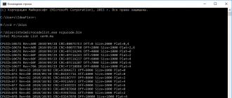
As a compromise, I chose the following solution - we take the latest versions of microcodes for all processors of the CORE generation in all designs (Celeron E, Pentium E, Core 2 Duo, Core 2 Quad, Xeon *3xxx/*5xxx) and replace with them everything that was before . The set of microcodes turned out to be as follows:

The volume of this set is only 76 kilobytes. This file was obtained by combining these files:
cpu00010676_plat00000001_ver0000060f_date20100929.bin
cpu00010676_plat00000004_ver0000060f_date20100929.bin
cpu00010676_plat00000010_ver0000060f_date20100929.bin
cpu00010676_plat00000040_ver0000060f_date20100929.bin
cpu00010677_plat00000010_ver0000070a_date20100929.bin
cpu0001067a_plat00000011_ver00000a0b_date20100928.bin
cpu0001067a_plat00000044_ver00000a0b_date20100928.bin
cpu000006f2_plat00000001_ver0000005d_date20101002.bin
cpu000006f6_plat00000001_ver000000d0_date20100930.bin
cpu000006f6_plat00000004_ver000000d2_date20101001.bin
cpu000006f7_plat00000010_ver0000006a_date20101002.bin
cpu000006f7_plat00000040_ver0000006b_date20101002.bin
cpu000006fb_plat00000001_ver000000ba_date20101003.bin
cpu000006fb_plat00000004_ver000000bc_date20101003.bin
cpu000006fb_plat00000010_ver000000ba_date20101003.bin
cpu000006fb_plat00000040_ver000000bc_date20101003.bin
cpu000006fd_plat00000001_ver000000a4_date20101002.bin
The modification procedure itself has also changed a little and has become, if not easier, then faster:
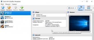
Step 1— open the BIOS image in the MMTool program: 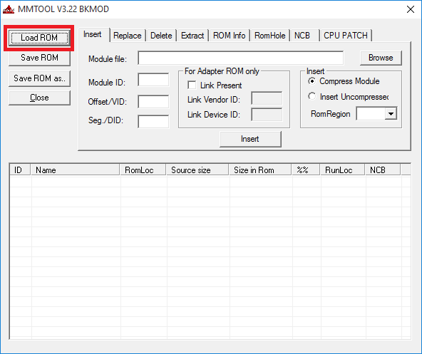

Step 2— to check, go to the last tab (CPU PATCH) and look at the number of microcodes. Here, for example, there are 31 of them: 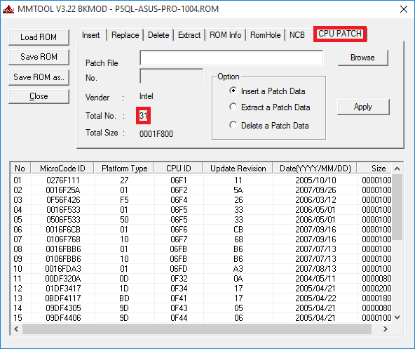
Step 3— go to the Replace tab and look for the “P6 Micro Code” item on it: 
Step 4— having selected the “P6 Micro Code” item, press the Ikshtsyu button, select the ncpucode.bin file described above and replace it with the Replace button: 


Step 5— to check, go to the last tab (CPU PATCH) and look at the number of microcodes. After replacing the microcodes, 17 remained, the latest version: 
There is no fundamental difference with the modification procedure described on delidded.com. In most cases, the output is certainly not the same, but the processor receives the necessary microcode. Of the subjective positive aspects, I would only like to draw attention to the fact that the microcodes for all current processors are guaranteed to be updated, be it “civilian” or “server”, and there is practically no risk of receiving a message about lack of space. Although, in my practice, even for such a set of microcodes there was not enough space a couple of times, this was with the BIOS for the ECS P4M900T-M and ECS P4M900T-M2 boards, which are generally compatible with the Xeon E5450.
By tradition, I publish a link to the archive with tools - (zip, 234KB). The archive contains an executable file MMTOL.exe(version 3.22 BKMOD), file with microcodes for all 45/65nm processors of the core/xeon generation ncpucode.bin, as well as two files 45nm.bin And 65nm.bin with microcodes only for 45nm processors and only for 65nm. The use of these files can be useful in cases where it is necessary to free up additional space in the BIOS, for example, for new firmware of some controller, network, disk, etc.
!NB: Neither the ncpucode.bin file nor the 45nm.bin/65nm.bin files support Pentium 4, Celeron (without letter suffixes), Pentium D, Celeron D and Xeon W processors (Xeon 5080 for example). These are NetBrust generation processors.
- Tutorial
In this article I will try to talk about the most popular and useful UEFI BIOS modifications, the conditions for their use and search methods. In addition, the light has not yet reached the point of view of the UEFITool utility described in the utility, so other programs used to modify UEFI BIOSes from various manufacturers will also be mentioned.
If the topic is interesting to you, welcome to cat.
In PowerManagement the code looks different, most often like this:
80 FB 01 cmp bl,1 ; If BL == 1 75 08 jne 0000000180002700 ; Jump over the next two commands 0F BA E8 0F bts eax,0Fh ; Set bit 15 (LOCK) 89 44 24 30 mov dword ptr ,eax ; Save the result to a variable on the stack 48 8B 54 24 30 mov rdx,qword ptr ; Load the value from this variable into RDX B9 E2 00 00 00 mov ecx,0E2h ; And the MSR number in ECX E8 is 79 0C 00 00 call 0000000180003388; And call the function with wrmsr insideYou can replace JNE with JMP, BTS with BTR, or simply replace the entire lock installation code. The easiest way is to do the first one, i.e. change 75 08 to EB 08.
If such code is not found in your UEFI BIOS, look for the value 0xE2 in the drivers related to CPU Power Management, and check all the code to see if the 15th bit is set. In the latest BIOS versions for some modern desktop AMI boards, they no longer lock this register, so you can no longer find such code in them - consider that the manufacturer made this mod for you.
AES NI unlock
What: Bypass setting the LOCK bit (0x02) to the MSR register 0x13CFor what: Enable AES hardware acceleration on systems with export restrictions
Where to look: in UEFI drivers related to CPU PM, most often in PowerManagement
Modification method: not much different from PM patch (and narrower), so I won’t dwell on it in detail.
Whitelist removal
What: bypass the white list of compatible equipment that some laptop manufacturers use in their UEFI BIOSes.For what: The manufacturer’s idea is clear - you can also sell rebranded compatible equipment to owners of “incompatible” equipment at exorbitant prices. If you want to decide for yourself what equipment is compatible with your laptop, this modification is for you.
Where to look: in UEFI drivers related to PCIe devices. For HP this driver is usually called BiosLockPcie, for Lenovo it is LenovoWmaPolicyDxe.efi, but it may be called differently.
Modification method: because As laptop manufacturers try to change the Whitelist verification code more often, it is quite difficult to describe a permanent method.
The general search strategy is:
- Insert an incompatible card into the laptop, wait for the message about the impossibility of loading and remember it.
- Find this message in one of the FFS files.
- Find the code that references this message.
- Examine this code and try to change it so that the check always succeeds. There are two ways to do this: either patch the transition, or add your Vendor ID and Device ID to the white list.
The check is carried out by the LenovoWmaPolicyDxe.efi driver, you need to go here:
44 38 0D F0 0F 00 00 cmp byte ptr ,r9b 75 18 jne 0000000000000C1A E8 35 FD FF FF call 000000000000093C 48 85 C0 test rax,rax 4C 8B C8 mov r9,rax 0F 88 77 FF FF FF js 0000000000000B8A C6 05 D6 0F 00 00 01 mov byte ptr ,1 49 8B C1 mov rax,r9 E9 68 FF FF FF jmp 0000000000000B8AAll transitions to this code must be patched to unconditional ones, and in the code itself it is necessary to “patch” the first and second lines, after which the check will always end successfully.
BIOS lock removal
What: removing protection from flashing modified UEFI images using the built-in programmer.For what: with a large number of experiments with UEFI, getting the programmer out every time quickly gets boring, and firmware with the built-in programmer is faster (due to the work using the QuadSPI protocol instead of ordinary SPI in the case of an external programmer).
Where to look: in chipset drivers, most often in PchInitDxe (another mod option is in BiosWriteProtect)
Modification method: The PchInitDxe modification option is completely described in English, so I will only give the idea. It is necessary to find the entry of the BIOS Lock Enable (BLE) bit into the BIOS_CNTL register of the chipset and prevent it. This can be done in several places, for example here:
48 8B 4C 24 40 mov rcx,qword ptr ; Load the address of the PchPlatformData structure into RCX 48 8B 41 50 mov rax,qword ptr ; And in RAX - the address of the child structure LockdownConfig F6 00 10 test byte ptr ,10h ; Check if the fifth bit is set (BiosLock) 74 25 je 0000000180001452 ; If not installed, jump over all code below 8A 50 01 mov dl,byte ptr B9 B2 00 00 00 mov ecx,0B2h ; E8 A2 5A 00 00 call 0000000180006EDC 4C 8D 87 DC 00 00 00 lea r8, ; RDI contains the base address of the chipset's LPC registers, and 0xDC is the offset of the BIOS_CNTL register 33 C9 xor ecx,ecx 4C 8B CD mov r9,rbp 33 D2 xor edx,edx 4C 89 44 24 20 mov qword ptr ,r8 E8 AA 76 00 00 call 0000000180008AFC ; Install lockYou can change JE to JMP, but sometimes instead of a short jump you come across a long one, for which you have to additionally calculate the offset, so it is better to change test to any command that sets the ZF flag, for example to xor rax, rax (48 31 C0), and the possible difference in size commands corrected by adding NOPs.
If the required code is not found in PchInitDxe, you can modify the BiosWriteProtect driver in such a way as to bypass the registration of the SMI handler located in it, which sets the BLE bit when you try to reset it, after which you just need to reset this bit to unlock the firmware. The method described above works fine for me, so I haven’t tried this option yet and therefore I won’t describe it in detail.
Advanced settings unlock
What: Unlocks access to hidden BIOS Setup settings.For what: among these settings you may find something interesting, but usually they are hidden for a reason.
Where to look: For Phoenix and Insyde, the menu is stored in HII files with names like SetupMain, SetupAdvanced, etc. For AMI, the menu is stored in the Setup file and the settings are stored in AMITSE. Moreover, AMI provides its AMIBCP program to manufacturers of end-user products, versions of which are often leaked to the public. Working with it is quite simple, so I see no point in describing it - download it and try it.
Modification method: for AMI - open the image in AMIBCP, change the default settings, save, flash, reset, done. For Insyde and Phoenix, things are a little more complicated. If write access to NVRAM is not prohibited, you can use friend’s method Falseclock, described in, but if there is no access, you will have to modify the firmware. You will need to parse the HII Form File format either manually, or provide this to the script described in the above-mentioned article, or to the Universal IFR Extractor utility, which must be applied to the HII files extracted from the UEFI image. After this, just change the SUPRESS_IF conditions in the extracted HII Form file so that they are never executed, and all menus will become available.
CPU Microcode, OptionROM, drivers and images update
What: updating CPU microcodes, firmware of various peripheral devices, EFI drivers and images displayed during boot and in BIOS Setup.For what: sometimes an update helps fix errors in the system, sometimes it adds support for an important feature (TRIM for SSDs in RAID0, for example), but most often the update is done because a new version has finally been released.
Where to look: highly depends on the manufacturer, EFI drivers can be found simply by name (SataDriver, for example), microcode can be found by the Model ID of the processor for which it is intended, OROMs - by the VID/DID of the devices they serve, pictures in JPEG format can be found find by the line “JFIF”, in GIF - by “GIF8”, etc.
Modification method: as simple as mooing - find a new version in the public domain, find where the old one is in the image, and replace one with the other. For AMI comrade LS_29 a set for automatic updating was written based on the MMTool utility, you can download it from our topic on over. I haven't heard of automated solutions for Phoenix or Insyde yet.
Replacing images can be done either with utilities like AMI ChangeLogo, or manually, but most often an image that is not prepared in a special way causes a freeze, because Image format decoders are very limited. In general, it is better to delete EXIF data in advance.
Conclusion
In this article, I described only those mods that I successfully made with my own hands. If you have any comments or additions, I will be glad to receive your comments.Once again, I humbly ask the Habr administration and UFO personally to create a UEFI hub, because this is a very broad topic, and there is literally nowhere to put articles on it.
Thank you for your attention, I wish you successful modifications.
Tags:
- UEFI
- modification
- UEFITool
BIOS (Basic Input/Output System) program code is born in developer laboratories.
The most famous of them are Award and AMI.
Each motherboard manufacturer then tailors the BIOS to a specific model and disables (blocks) certain features at its discretion.
Moreover, many functions that affect the “fine” tuning of the BIOS, and on which, in turn, the performance of the computer depends, may be blocked.
Why do motherboard manufacturers block some functions?
First of all, this is done to simplify the Setup BIOS setup procedure.
They also disable those functions that are not present in a particular motherboard, but can be used in the following modifications.
Using special software (utilities), you can unlock almost all disabled functions and options in the BIOS.
After modification, the results must be saved in a separate file and then the BIOS must be updated.
When you load Setup BIOS, you will see new additional configuration options on the monitor screen.
Each company needs its own utility.
Award BIOS owners will need the Modbin utility, and for those who have an AMI BIOS installed on their computer, you need to download the AMIBCP program.
An interesting fact is that the AMIBCP utility was developed by programmers from AMI itself.
Practice
First of all, you should prepare the necessary software.
To modify, you will need an update utility (“flasher”), a file with the current BIOS version, and a modification utility.
The flashing utility can be found on the Internet on the website of the motherboard manufacturer or on the CD included with the motherboard.
After which it must be copied to the computer’s hard drive.
The file containing the current BIOS version can be obtained using this utility.
BIOS modification utilities can be downloaded from the Internet.
As an example, consider the case when an AMI BIOS is installed on the computer.
As for the Award BIOS, the modification principle is similar and will not be discussed in this article.
The AMIBCP utility is a DOS program and boots without problems under Windows without rebooting into MS-DOS emulation mode.
AMIBCP volume (file amibcp75.exe) in unpacked form is 542 KB.
After loading the AMIBCP utility, you must use the keyboard to enter the name of the file containing the BIOS, for example, 7vr_f4.bin .
Next, being in the main menu of the program, look for the section “ Configure Setup Data" and look through all the subsections in order.
Of particular interest to us will be the subsections “ Chipset Setup" And " BIOS Features Setup».
The modification itself consists of activating blocked options.
Each subsection contains columns with headings “ Option Name», « Active», « Rights», « Optimal" And " FailSafe».
Locked options are highlighted next to these options in the column " Active" value specified " No».
Keys Page Up And Page Down you can use one or another blocked installation.
There may be cases where the column with the heading " Option Name"The names of the options are completely absent on the screen.
In this case, you will have to enable all the options in a row “blindly”.
Having completed the changes, go to the main menu of the AMIBCP program and, by pressing the key, save the modified BIOS to a file.
After saving the modified file, use the “flasher” - a utility for updating the BIOS.
Conclusion
A number of motherboard manufacturers release their proprietary programs for updating the BIOS directly in the Windows environment.
These include utilities from Gigabyte, ASUS, Intel, etc.
Before flashing the firmware, you should make sure that updating is allowed in Setup BIOS - in the BIOS Features Setup section, the BIOS Flash Protection parameter should be in the Disabled or Auto position.
After flashing, reboot the computer and enter Setup BIOS.
In modification practice, there were cases when settings in the BIOS were blocked that could improve system performance.
Namely: the ability to change the voltage on the AGP bus in the range of 1.5 - 1.8 V in steps of 0.1 V and on DDR memory modules in the range of 2.5 - 2.8 V in steps of 0.1 V, as well as increase at 5, 7.5 or 10% nominal voltage on the processor core.
There have been cases where S.M.A.R.T. mode was blocked in the BIOS. for hard drives and Bypass Mode for optimal CPU performance.
The blocked option in the Hardware Monitor subsection - Slow Down CPU Duty Cycle was also interesting.
When the system enters Doze mode, the CPU clock speed decreases.
Using this option, you can set a different CPU clock speed as a percentage of the previous one.
In conclusion, I would like to remind you: you shouldn’t lose your head over complete control over the BIOS.
And therefore, modification and change of parameters should be approached with some caution and with an understanding of what you are doing and what you are going for.