It is a useful device that is used in many areas of human activity, from household life to industry. In various grinding machines, on conveyors, machine tools, industrial ventilation systems and more. The electric motor has 3 outputstherefore, a star and delta connection to a three-phase AC network or transformer can be made.
Engine design
The windings are located on the stator, and the rotor is made short-circuited in the form of a squirrel wheel: aluminum or copper rings at the ends are interconnected by parallel jumpers. The stator is wound in a special way with a certain number of poles, which depends on the parameters of power and the mains. Domestic fans have only 2 poles, industrial traction motors of 8 or more.
Benefits of Using Asynchronous electric motors with a star or triangle switching circuit are obvious and are as follows:
Network Connection Methods
Now let's try to figure out what a star and a triangle are, what is the difference between them. 3-phase asynchronous motor has 3 windings that are connected in a certain way. They can be connected both to a 380 V network and to an alternating voltage of 220 V. Therefore, the engine can be considered universal, but its quality of work directly depends on the method of connection to the network or to a separate supply transformer.
For example, in acceleration mode, when it is connected in series to the motor circuit to reduce the starting voltage. According to this principle, a frequency converter operates, adjusting the initial moment by changing the frequency, preventing excess power consumption by more than 10-20%. In the normal start-up mode, the induction motor consumes up to 600% of the nominal value, which can cause automatic shutdown of input machines.
Usually, when you open the terminal box on the motor, you can see 3 pins and an additional twist. This indicates the type of connection of the windings, which in this case is a star. Having untwisted the general connection, you will receive 6 conclusions which are the ends and the beginnings of each of the 3 windings. Therefore, it becomes possible to connect according to the triangle pattern.
Sometimes, depending on the control method and the algorithm for generating the control voltage in the drive, switching from a star to a triangle is required. And you can do it automatically mode, for example, during acceleration, so that the electric motor immediately provides high torque. This is most often used in frequency control systems, where it is necessary to more strictly regulate the dynamics of the engine and control the speed of rotation.
When and which scheme is best to use depends on the requirements, but each of the methods has its own characteristics. For example, they consist of developed and consumed power, the difference between linear and phase voltages, and, accordingly, dynamic and electrical indicators.
Basic formulas
Before you get acquainted with the features of how to connect a star-delta electric motor, it is worth recalling the basic formulas for calculating power and the ratio of voltages and currents between them. When calculating powered devices from an alternating voltage network or a separate transformer, the concept of full power is used. It is indicated by a capital S and is found as the product of the effective voltage and current U × I. Also, it is possible to calculate based on the EMF at which S \u003d E × I.
In addition to the full, also distinguish:
- active;
- reactive power.
 In the first case, it is denoted by the letter P \u003d E × I × cos φ or P \u003d U × I × cos φ. In the second case, Q \u003d E × I × sin φ or Q \u003d U × I × sin φ. Where in the formulas E is the electromotive force, I is the current, φ is the angle between the voltage and the current created by the phase shift in the windings.
If the motor windings are identical with each other in all parameters, then all types of power are defined as the product of current and voltage multiplied by 3.
Motor star connection
The most commonly used is the star connection, because in this mode the necessary power is provided and good torque on the shaft is guaranteed. But it is worthwhile to understand that an underloaded motor in a 3-phase network will consume excess power, therefore it is better to use a less powerful motor or adjust the frequency of the supply transformer or drive, depending on the voltage source.
And to determine the electrical parameters of the network, it is necessary to use the relation √3. Initially, it should be noted that when connecting to a star, the linear and phase currents are the same, and the voltage is determined by the formula U \u003d √3 × U f. It is not difficult to find the phase voltage from it. Accordingly, the power is determined taking into account this ratio:
S \u003d √3 × U × I
It should be remembered that if on the transformer, in addition to the 3 phases, there is also a 4th output from the midpoint, then it must be connected to the electric motor .
Features of the application of connection to the star
 In enterprises, and in all other areas, the main type of connection of 3-phase motors is just a star, and they are powered from a common substation or a separate transformer, thus providing galvanic isolation. The inclusion circuit of its windings does not particularly affect the operation of the engine. If they are connected in a triangle, then the output voltage will be 1.73 times less and by connecting the motor to its windings according to the triangle scheme, you can achieve about the same moment as in normal mode.
The phase currents when connecting according to the circuit in the star are equal, and the voltage supplied to each of the windings is 1.73 times less. The engine is gaining its momentum over a longer time, but it does not overheat. In this mode, motors are used on fans, pumps, screws and other units. But, if it is necessary to increase the moment and traction ability, then it is briefly switched to a triangle.
In this case, the mains voltage is supplied to the windings, and, consequently, the increased current, which leads to the allocation of additional power to the shaft and heating of the motor. The mode of switching to the triangle is used to accelerate the start of the engine, and therefore return the wiring diagram to its original state. Long work in this mode will lead to an early failure.
Induction motors have many operational advantages. This is reliability, high power, good performance. The connection of the electric motor with a star and a triangle ensures its stable operation.
At the heart of the electric motor there are two main parts: a spinning rotor and a static stator. Both have a set of conductive windings in the structure. The electrical windings of the fixed element are located in the grooves of the magnetic wire at a distance of 120 degrees. All ends of the windings are displayed in the electrical distribution block, they are fixed there. Contacts are numbered.
Engine connections can be a star, a triangle, as well as all kinds of switching. Each connection has its own advantages and disadvantages. Engines connected according to the star scheme have smooth, soft operation, the action of the electric motor is limited by power compared to a triangle, since its value is one and a half times greater.
- Combining at one common point: connecting a star
- Mixed way
- Principle of operation
An association at one common point: connecting star
The ends of the stator windings are connected together at one point. Three-phase voltage is supplied to the beginning of the windings. The value of the starting currents when connecting the triangle is more powerful. Star connection means a summary of the ends of the stator winding. Voltage is applied to the beginning of each winding.
The windings are connected in series with a closed cell, form a triangular connection. The rows of contacts with the terminals are arranged parallel to each other. For example, the beginning of terminal 1 is opposite the end 1. The mains power is supplied to the stator windings, creating a rotation of the magnetic field, leading to the movement of the rotor. The torque that occurs after connecting a three-phase electric motor is insufficient to start. The increase in the rotational element is achieved by using an additional element. For example, a three-phase chastotnik connected to an induction motor in the figure below.

Star wiring diagram of a classic frequency converter
According to this scheme, domestic 380 volt motors are connected.
Mixed way
Combined connection type is applicable for electric motors with power from 5 kW. The star-delta circuit is used if necessary to reduce the starting currents of the unit. The principle of operation begins with a star, and after the engine has set the desired speed, the system automatically switches to a triangle.

To save on electricity bills, our readers recommend the Electricity Saving Box. Monthly payments will be 30-50% less than they were before using the economizer. It removes the reactive component from the network, resulting in reduced load and, as a result, the current consumption. Electrical appliances consume less electricity, reducing the cost of its payment.
This scheme is not suitable for devices with overloads, as there is a weak torque, which can lead to breakage.
Principle work
 The power is started using the second and relay contact. Then, the third starter is activated on the stator, thereby opening the circuit formed by the coil of the third element, it closes. Next, the first stator winding begins to work. Then a short circuit occurs in, a temporary thermal relay is triggered, which closes at the third point. Next, there is a contact closure of the temporary thermal relay in the circuit of the second stator winding. After disconnecting the windings of the third element, the contacts are closed in the chain of the third element.
To the beginning of the windings, current flows in three phases. It enters through the power contacts of the magnet of the first element. The contacts of the third starter include it, close the ends of the windings, which are connected by a star.
Then the time relay of the first starter turns on, the third turns off, and the second turns on. Contacts K2 close, voltage is supplied to the ends of the windings. This is the inclusion of a triangle.
Various manufacturers make the start relay necessary to start the electric motor. They differ externally in name, but perform the same function.
 Typically, the connection to the network 220 is a phase-shifting capacitor. Power comes from any power supply, rotates the rotor with the same frequency. Of course, the power from a three-phase network will be greater than from a single-phase. If a three-phase motor runs on a single-phase network, power is lost.
Some types of motors are not designed to work from a household network. Therefore, choosing a device for the home, preference should be given to engines with squirrel-cage rotors.
According to the rated power supply, domestic electric motors are divided into two types: power 220 - 127 volts and 380 - 220 volts. The first type of electric motors of low power is rarely used. The second devices are widespread.
When installing an electric motor of any power, a certain principle applies: devices with low power are connected according to the triangle scheme, and high connected by a star. Power 220 is supplied to the summary by a triangle, voltage 380 goes to the star connection. This will ensure a long and high-quality operation of the mechanism.
The recommended circuit for connecting the motor is listed in the technical document. A △ indicates a connection in the same form. The letter Y indicates the recommended star connection diagram. The characteristics of numerous elements are indicated by colors, due to their small dimensions. The color reads, for example, face value, resistance. If there are both signs, then the connection is possible by switching △ and Y. When there is one specific marking, for example, Y, then the available connection will be only in the star pattern.

Scheme △ gives output power up to 70 percent, the value of inrush currents reaches a maximum value. And it can ruin the engine. This scheme is the only option for working from Russian electric networks of foreign asynchronous motors with a capacity of 400 - 690 volts.
Therefore, choose the correct connection or switching, it is necessary taking into account the features of the electrical network, the power of the electric motor. In each case, you should familiarize yourself with the technical characteristics of the motor and the equipment for which it is intended.
Motors of asynchronous type have a whole set of unconditional advantages. Among the advantages of induction motors, first of all, I want to name the high performance and reliability of their operation, the very low cost and unpretentiousness of repair and maintenance of the motor, as well as the ability to tolerate sufficiently high mechanical type overloads. All these advantages possessed by asynchronous motors are due to the fact that this type of motor has a very simple design. But, despite a large number of advantages, asynchronous motors are inherent in their certain negative aspects.
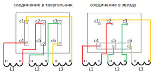
In practical work, it is customary to use two main methods of connecting three-phase electric motors to the mains. These connection methods are called star connection and delta connection.
When a three-phase electric motor is connected by the star connection, then the ends of the stator windings of the electric motor are connected at one point. In this case, a three-phase voltage is applied to the beginning of the windings. Below, in Figure 1, the wiring diagram of an asynchronous star motor is clearly illustrated.
When a three-phase motor is connected by the type of connection "triangle", then the stator windings of the electric motor are connected in series with each other. In this case, the beginning of the subsequent winding is connected to the end of the previous winding and so on. Below, in Figure 2, the connection diagram of the “triangle” asynchronous motor is clearly illustrated.

If you do not go into the theoretical and technical fundamentals of electrical engineering, you can take for granted the fact that the operation of those motors in which the windings are connected in the "star" circuit is softer and smoother than in electric motors whose windings are connected in the "triangle" pattern " But here it is worth paying attention to the feature that electric motors, the windings of which are connected according to the "star" scheme, are not able to develop the full power stated in the rating characteristics. In that case, if the windings are connected according to the "triangle" scheme, then the electric motor operates at the maximum power, which is stated in the technical data sheet, but at the same time there are very high values \u200b\u200bof inrush currents. If we compare by power, then the electric motors whose windings will be connected according to the "triangle" circuit are capable of delivering power one and a half times higher than those electric motors whose windings are connected according to the "star" circuit.
Based on all of the above, in order to reduce currents at startup, it is advisable to use the connection of the windings according to the combined triangle-star circuit. This type of connection is especially relevant for electric motors with greater power. Thus, in connection with the connection according to the "triangle-star" scheme, the initial start-up is performed according to the "star" scheme, and after the electric motor has "gained speed", automatic switching according to the "triangle" scheme is performed.
The motor control circuit is shown in Figure 3.

Fig. 3 control circuit
Another version of the motor control circuit is as follows (Fig. 4).

Fig. 4 Engine management
The NC contact (normally closed) of the K1 time relay, as well as the NC contact of the K2 relay, in the short circuit of the KZ starter coil, is supplied with a supply voltage.
After switching on the short-circuit starter, normally closed contacts of the short-circuit disconnect the starter coil circuit K2 (prohibition of accidental switching on). Short circuit contact in the power supply circuit of the starter coil K1 closes.
When the magnetic starter K1 starts, the contacts K1 are closed in the power circuit of its coil. The time relay turns on at the same time, the contact of this relay K1 in the short circuit of the short circuit starter coil opens. And in the starter coil circuit K2 - closes.
When the short circuit of the starter short circuit is disconnected, the short circuit contact is closed in the starter coil circuit K2. After the K2 starter is turned on, it opens with its contacts K2 the power circuit of the short circuit starter coil.
A three-phase supply voltage is supplied to the beginning of each of the windings W1, U1 and V1 using the power contacts of the starter K1. When the short-circuit magnetic starter is triggered, then using its short-circuit contacts, a short circuit is performed, through which the ends of each of the windings of the electric motor W2, V2 and U2 are connected to each other. Thus, the connection of the motor windings is performed according to the star connection diagram.
The time relay, combined with the magnetic starter K1, will operate after a certain time. In this case, the magnetic short circuit starter is turned off and the magnetic starter K2 is simultaneously turned on. Thus, the power contacts of the starter K2 will close and the supply voltage will be applied to the ends of each of the windings U2, W2 and V2 of the electric motor. In other words, the electric motor is switched on according to the "triangle" connection diagram.
In order to start the electric motor according to the "star-delta" connection scheme, various manufacturers produce special starting relays. These relays can have various names, for example, the "start-delta" or "start time relay", as well as some others. But the purpose of all these relays is the same.
A typical circuit made with a time relay designed to start, that is, a delta-star relay for controlling the start-up of a three-phase asynchronous electric motor, is shown in Figure 5.

Fig. 5 Typical circuit with a starting timer (star / delta relay) for controlling the starting of a three-phase asynchronous motor.
So, to summarize all of the above. In order to reduce the starting currents, it is necessary to start the electric motor in a certain sequence, namely:
- first, the electric motor is started at reduced speeds connected in a star pattern;
- then the electric motor is connected according to the "triangle" scheme.
The initial start-up according to the "triangle" scheme will create the maximum moment, and the subsequent connection according to the "star" scheme (for which it is 2 times less than the starting moment) with continued operation in the nominal mode, when the engine "gained speed", there will be a switch to the "triangle" connection scheme "in automatic mode. But do not forget about what kind of load is created before starting on the shaft, since the torque is weakened when connected according to the "star" scheme. For this reason, it is unlikely that this starting method will be acceptable for motors with a high load, since in this case they may lose their performance.
An asynchronous electric motor is an electromechanical equipment that is widespread in various fields of activity, and therefore familiar to many. Meanwhile, even taking into account the close connection of the asynchronous electric motor with the people, the rare “electrician to himself” is able to reveal the whole background of these devices. For example, not every “pliers holder” can give exact advice: how to connect the motor windings with a “triangle”? Or how to put jumpers on the star windings of the motor windings? Let us try to reveal these two simple and at the same time complex questions.
As Anton Pavlovich Chekhov used to say:
Repetition is the mother of learning!
To begin the repetition of the topic of electric induction motors is a logical detailed review of the design. built on the basis of the following structural elements:
- aluminum case with cooling elements and mounting chassis;
- stator - three coils wound with a copper wire on a ring base inside the housing and placed opposite one another under an angular radius of 120º;
- rotor - a metal disc, rigidly mounted on the shaft, inserted into the annular base of the stator;
- thrust bearings for rotor shaft - front and rear;
- housing covers - front and rear, plus an impeller for cooling;
- BRNO - the upper part of the case in the form of a small rectangular niche with a cover, where the terminal block for fastening the terminals of the stator windings is located.
Here, in fact, the whole structure. Most of the induction motors are the prototype of just such a design. True, sometimes there are instances of a slightly different configuration. But this is an exception to the rule.
Designation and wiring of stator windings
A rather large number of asynchronous motors, where the designation of the stator windings are made according to an outdated standard.
Such a standard provided for marking with the symbol “C” and adding a number to it - the number of the output of the winding, indicating its beginning or end.
Moreover, the numbers 1, 2, 3 always refer to the beginning, and the numbers 4, 5, 6, respectively, indicate the ends. For example, markers “C1” and “C4” indicate the beginning and end of the first stator winding.
 Marking of the end parts of the conductors output to the BRNO terminal block: A - obsolete designation, but still found in practice; B is a modern designation traditionally present on markers of conductors of new motors
 Modern standards have changed this marking. Now the symbols noted above have been replaced by others that correspond to the international model (U1, V1, W1 are the starting points, U2, V2, W2 are the end points) and are traditionally found when working with new generation asynchronous motors.
Conductors emanating from each of the stator windings are displayed in the terminal box area, which is located on the motor housing and connected to an individual terminal.
In total, the number of individual terminals is equal to the number of output starting and ending wires of the common winding. Usually these are 6 conductors and the same number of terminals.
 This is what the standard engine terminal block looks like. Six terminals are connected with brass (copper) jumpers before connecting the motor to the appropriate voltage
 Meanwhile, there are also variations in the separation of conductors (rarely and usually on older motors), when 3 wires are led out to the BRNO area and only 3 terminals are present.
How to connect the "star" and "triangle"?
The connection of an asynchronous electric motor with six conductors brought to the terminal box is carried out by standard methods using jumpers.
By properly placing jumpers between the individual terminals, it is easy and simple to set up the required circuit configuration.
So, to create an interface for connecting with a “star”, it is necessary to leave the initial winding conductors (U1, V1, W1) on individual terminals, and connect the terminals of the terminal conductors (U2, V2, W3) with jumpers.
 Star connection diagram. It has a high demand for line voltage. Gives the rotor a smooth run in start mode
 If you need to create a “triangle” connection diagram, the layout of the jumpers changes. To connect the stator windings with a triangle, you need to connect the starting and end conductors of the windings according to the following scheme:
- initial U1 - terminal W2
- initial V1 - terminal U2
- start W1 - end V2
 Connection diagram "triangle". A distinctive feature - high inrush currents. Therefore, often the motors according to this scheme are pre-launched on the "star" with the subsequent transfer to the operating mode
 Connection for both circuits, of course, is assumed in a three-phase network with a voltage of 380 volts. There is no particular difference when choosing one or another circuit option.
However, the great need for line voltage for the star circuit should be considered. This difference, in fact, shows the marking "220/380" on the technical plate of the motors.
The star-delta series connection option is seen as the optimal starting method for a 3-phase AC induction motor. This option is often used to smoothly start the motor at low initial currents.
Initially, the connection is organized according to the "star" scheme. Then, after a certain period of time, the connection to the "triangle" is performed instantly.
Connection based on technical information
Each induction motor is necessarily equipped with a metal plate, which is mounted on the side of the housing.
Such a plate is a kind of equipment identifier panel. It contains all the necessary information required for the correct installation of the product in the AC network.
 Technical plate on the side of the engine housing. All important parameters required to ensure normal operation of the motor are noted here.
 This information should not be neglected, including the motor in the electric power supply circuit. Violations of the conditions noted on the information plate are always the first reasons for the failure of motors.
What is indicated on the technical plate of the induction motor?
- Type of motor (in this case, asynchronous).
- Number of phases and operating frequency (3F / 50 Hz).
- Winding circuit and voltage (delta / star, 220/380).
- Operating current (on the "triangle" / on the "star")
- Power and speed (kW / rpm).
- Efficiency and COS φ (% / coefficient).
- Insulation mode and class (S1 - S10 / A, B, F, H).
- Manufacturer and year of manufacture.
Turning to the technical plate, the electrician already previously knows under what conditions it is permissible to turn on the motor in the network.
From the point of view of connecting with a “star” or “triangle”, as a rule, existing information lets an electrician know that a connection with a “triangle” is correct in a 220V network, and an asynchronous electric motor should be connected with a “star” on a 380V line.
Test the motor or operate it only if wiring through the protective. At the same time, the machine introduced into the circuit of the asynchronous electric motor should be correctly selected according to the cutoff current.
Three-phase asynchronous electric motor in a network 220V
Theoretically and practically the same, an asynchronous electric motor, designed to connect to the network through three phases, can operate in a single-phase 220V network.
As a rule, this option is relevant only for motors with a power not exceeding 1.5 kW. This limitation is explained by the banal deficit of the capacity of the additional capacitor. At high powers, a capacitance for high voltages, measured in hundreds of microfarads, is required.
 Using a capacitor, you can organize the operation of a three-phase motor in a 220 volt network. However, in this case, almost half of the useful power is lost. The level of efficiency is reduced to 25-30%
 Indeed, the simplest way to start a three-phase asynchronous electric motor in a single-phase 220-230V network is to make a connection through the so-called starting capacitor.
That is, of the three existing terminals, two are combined into one by connecting a capacitor between them. Thus formed two network terminals are connected to a 220V network.
By switching the power cord at the terminals with a connected capacitor, you can change the direction of rotation of the motor shaft.
 By connecting a capacitor to a three-phase terminal strip, the connection diagram is transformed into a two-phase. But for a clear engine performance, a powerful capacitor is required
 The nominal capacitance of the capacitor is calculated by the formulas:
Szv \u003d 2800 * I / U
C mp \u003d 4800 * I / U
where: C is the desired capacity; I is the starting current; U is the voltage.
However, simplicity requires sacrifice. So it is here. When approaching the solution of the start-up problem with the help of capacitors, a significant loss of motor power is noted.
To compensate for the losses, it is necessary to find a large capacitor (50-100 uF) with an operating voltage of at least 400-450V. But even in this case, it is possible to gain power no more than 50% of the nominal.
Since such solutions are most often used for asynchronous electric motors, which are supposed to be started and turned off, it is logical to apply a scheme that is somewhat modified compared to the traditional simplified version.
 Scheme for organizing work in a 220 volt network, taking into account frequent on and off. The use of several capacitors allows to some extent compensate for power losses.
 Minimum power losses are provided by the “triangle” switching circuit, in contrast to the “star” circuit. Actually, this option is also indicated by technical information that is placed on the technical plates of asynchronous motors.
As a rule, on the tag it is the “triangle” circuit that corresponds to the operating voltage of 220V. Therefore, in the case of choosing a connection method, first of all, you should look at the plate of technical parameters.
Custom terminal blocks BRNO
Occasionally, there are designs of asynchronous electric motors, where the BRNO contains a 3-pin terminal block. For such motors, the internal wiring diagram is used.
That is, the same “star” or “triangle” is schematically arranged by connections directly in the area of \u200b\u200bthe stator windings, where access is difficult.
 Type of non-standard terminal block, which may occur in practice. With this wiring should be guided solely by the information indicated on the technical plate
 Configuring such engines is somehow different, in everyday conditions it is not possible. The information on the technical plates of the motors with non-standard terminal blocks usually indicates the internal star circuit and the voltage at which it is permissible to operate an asynchronous motor.
Video turning on the motor 380V to 220V
The video below demonstrates how it is permissible to turn on an electric motor with a winding under a voltage of 380 volts to a network with a voltage of 220 volts (household network). Such a need is a common occurrence in everyday practice.
Content:
Asynchronous electric motors have proven themselves in such indicators as reliability in operation, the ability to obtain high torque power, excellent performance. An important indicator of the operation of these engines is the ability to switch to the star and delta connections - and this is stability during operation. Each connection has its own advantages, which must be understood with the correct use of induction motors.
Optimal motor connection selection
The conversion of the "star" into a "triangle" in an asynchronous electric motor, as well as the ability to repair the windings of the electric motor, and comparatively with other motors, low cost in combination with resistance to mechanical stresses made this type of motor the most popular. The main parameter that characterizes the dignity of induction motors is simplicity in design. With all the advantages of this type of electric motor, it also has negative aspects during operation.
In practice, three-phase asynchronous electric motors can be connected to the network according to the "star" and "triangle" schemes. A star connection is when the ends of the stator winding are tied to one point, and the network voltage of 380 volts is supplied to the beginning of each winding, this type of connection is schematically indicated by a sign (Y).

If the option "triangle" is selected in the switching box for connecting the electric motor, it is necessary to connect the stator windings in series:
- the end of the first winding - with the beginning of the second;
- connecting the end of the "second" - with the beginning of the third;
- the end of the third - with the beginning of the first.

Motor connection diagrams
Specialists, without going into the basics of electrical engineering, cite the fact that motors connected according to the "star" scheme work more softly than those connected according to the scheme triangle (Δ). This is a good circuit for low power engines. They also focus on the fact that during soft operation, when the star (Y) circuit is used, the electric motor does not gain rated power.
Choosing the best option for connecting an electric motor, one should consider the fact that the connection with a triangle (Δ) allows the motor to gain maximum power, but the value of the starting current increases significantly.
Comparing power indicators, this is the main difference between the star and triangle connections (Y, Δ), experts note that electric motors with a star connection (Y) have a power 1.5 times lower than connected by a triangle (Δ).
To reduce the current parameters at the time of start-up, it is recommended to use a star and delta motor connection, a combined switching circuit, in different switching circuits (Δ) - (Y). Combined, or it is also called mixed, the type of connection is recommended for electric motors with high rated power.

When the star connection circuit (Y) and (Δ) is turned on, the star connection (Y) works from the start of the start, after the motor has set sufficient speed, it switches to the delta connection (Δ). There are devices for automatically switching motor connections. Consider how the start-up circuits of electric motors differ and what is the difference between them.
How to control motor switching
Often, to start a high-power electric motor, the connection of the "triangle" connection to the "star" is used, this is necessary to reduce the current parameters at start-up. In other words, the engine starts in star mode, and all work is done on the triangle joint. For this purpose, a three-phase contactor is used.

It is necessary to fulfill the prerequisites for automatic switching:
- lock contacts from simultaneous operation;
- obligatory performance of work, with a time delay.
A time delay is necessary for a 100% disconnection of the star connection, otherwise when the connection is turned on, the triangle will occur between the phases of the short circuit. A time relay (RV) is used, which performs a switching delay of an interval from 50 to 100 milliseconds.

What are some ways to delay switching time?
When the “star and delta” scheme is used, it is imperative to delay the connection on-time (Δ) until the connection (Y) is disconnected, specialists prefer three methods:
- with the help of a contact normally open in the time relay, which locks the "triangle" circuit when the motor starts, and the switching moment controls the current relay (RT);
- using a timer in a modern time timer, which has the ability to switch modes at intervals of 6 to 10 seconds.

- by external control of starter contactors from automatic units or manual switching.

Standard switching circuit
The classic option of switching from a "star" to a "triangle" is considered by experts to be a reliable method, it does not require large expenses, is simple to execute, but, like any other method, it has a drawback - these are the overall dimensions of the relay (time relay). This type of RV is guaranteed to perform a time delay by magnetizing the core, and it takes time to demagnetize it.

The mixed (combined) inclusion circuit works as follows. When the operator turns on the three-phase switch (AB), the motor starter is ready for action. Through the contacts of the “Stop” button, a normally closed position and through the normally open contacts of the “Start” button, which is pressed by the operator, an electric current flows into the coil of the contactor (KM). Contacts (BKM) provide self-locking of power contacts and keep them in the on position.


The relay in the circuit (KM) provides the ability to disable the electric motor by the Stop button operator. When the "control phase" passes through the start button, it also passes through closed normally located contacts (BKM1) and contacts (RV) - the contactor (KM2) starts up, its power contacts supply voltage to the connection (Y), and the motor rotor starts spinning.
When the operator starts the engine, the contacts (BKM2) in the contactor (KM2) open, this generates an inoperative state of the power contacts (KM1), which provide power to the motor connection Δ.

The current relay (RT) is triggered almost immediately due to the high current values \u200b\u200bthat are included in the circuit of current transformers (TT1) and (TT2). The control circuit of the contactor coil (KM2) is bridged by the contacts of the current relay (RT), which does not work (RV).
In the contactor circuit (KM1), the contact block (BKM2) opens at startup (KM2), which prevents the coil (KM1) from tripping.

With a set of the desired parameter of the rotor speed of the motor rotor, the contacts of the current relay open, since the starting current decreases in the control of the contactor (KM2), simultaneously with the opening of the contacts supplying voltage to the winding connection (Y), the BKM2 is connected, which brings the contactor into operation (KM1 ), and in its circuit the BKM2 contact block opens, and, as a result, the RV is de-energized. The transformation of the inclusion of the "triangle" in the "star" occurs after the engine stops.
Important! The temporary relay does not turn off immediately, but with a delay, which allows the relay contacts to be closed for some time in the circuit (KM1), this ensures start-up (KM1) and engine operation according to the "triangle" scheme.

The disadvantages of the standard scheme
Despite the reliability of the classic circuit switching from one connection to another connection of an electric motor of high power, it has its disadvantages:
- it is necessary to correctly calculate the load on the motor shaft, otherwise it will gain speed for a long time, which will not allow the current relay to trip quickly and then switch to work on Δ connection, and also in this mode it is extremely undesirable to operate the motor for a long time;

- in order to avoid overheating of the motor windings, experts recommend including a thermal relay in the circuit;
- when the modern design of the PB is used in the classical design, the passport requirements for the shaft load must be observed;

Output
An important condition when using the star-delta connection diagram is the correct calculation of the load on the motor shaft. In addition, one cannot deny the fact that when the contactor of one connection Y is turned off and the motor has not yet reached the required speed, the self-induction factor is triggered, and an increased voltage is supplied to the network, which can bring other equipment and devices next to it from operating state.
Experts recommend that electric motors with an average power value be started according to scheme Y, which gives soft operation and a smooth start. The methods for selecting the inclusion differ in the available voltage at the facility, and in the load.