I talked about the background of the FLProg project. Now I want to tell you more about the project and its status today.
The main goal of the project is to include people unfamiliar with programming among the Arduino board users. This is possible thanks to the experience of industrial programming, which has been accumulated over the years by manufacturers of industrial controllers.
The project consists of two parts. The first part is the FLProg desktop application, which is a graphical programming environment for Arduino boards. Secondly, this is the site FLProg.ru, through which members of the program user community can communicate with each other, find out the latest project news, download the latest version of the program, and find the necessary information on working with the application.
Let's start in order.
The FLProg program allows you to create firmware for Arduino boards using the FBD and LAD graphic languages, which are the standard in the field of industrial controller programming.
FBD language description
FBD (Function Block Diagram) is a graphical programming language of the IEC 61131-3 standard. The program is formed from a list of circuits executed sequentially from top to bottom. When programming, sets of library blocks are used. A block (element) is a subroutine, function or functional block (AND, OR, NOT, triggers, timers, counters, analog signal processing blocks, mathematical operations, etc.). Each individual chain is an expression composed graphically of the individual elements. The next block is connected to the output of the block, forming a chain. Inside the chain, blocks are executed strictly in the order of their connection. The result of the circuit calculation is written to an internal variable or fed to the controller output.
Description of the LAD language
Ladder Diagram (LD, LAD, RKS) - relay (ladder) logic language. The syntax of the language is convenient for replacing logic circuits made on relay technology. The language is aimed at automation engineers working in industrial plants. Provides a clear interface to the logic of the controller, which facilitates not only the tasks of actual programming and commissioning, but also a quick troubleshooting in the equipment connected to the controller. The ladder logic program has a visual and intuitive graphical interface for electrical engineers, representing logic operations as an electrical circuit with closed and open contacts. The flow or absence of current in this circuit corresponds to the result of a logical operation (true - if current flows; false - if current does not flow). The main elements of the language are contacts, which can be figuratively likened to a pair of relay or button contacts. A pair of contacts is identified with a logical variable, and the state of this pair is identified with the value of the variable. A distinction is made between normally closed and normally open contact elements, which can be compared to normally closed and normally open pushbuttons in electrical circuits.
I slightly expanded the classic functionality of these languages by adding functional blocks responsible for working with external devices. They are wrappers for libraries designed to work with them.
A project in FLProg is a set of boards, on each of which a complete general circuit module is assembled. For convenience, each board has a name and comments. Also, each board can be rolled up (to save space on the working area when work on it is finished), and deployed. A red indicator in the board name indicates that there are errors in the board layout.
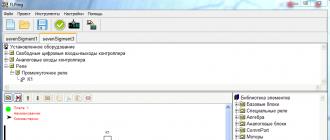
View of the program window in FBD language mode
View of the program window in LAD language mode 
The circuit of each board is assembled from functional blocks in accordance with the logic of the controller. Most of the function blocks have a configurable feature that can be used to customize their operation according to the needs of a particular application.

Also, for each functional block there is a detailed description that is available at any time and helps to understand its operation and settings.

When working with the program, the user does not need to write code, control the use of inputs and outputs, check the uniqueness of names and consistency of data types. All this is monitored by the program. It also checks the correctness of the entire project and indicates the presence of errors.
Several auxiliary tools have been created to work with external devices. This is a real-time clock initialization and configuration tool, tools for reading device addresses on OneWire and I2C buses, as well as a tool for reading and saving button codes on an IR remote control. All defined data can be saved as a file and subsequently used in the program.
List of function blocks currently existing in the FBD language
Basic elements
Special Blocks
triggers
Timers
Counters
Mathematics
Algebra
Comparison
Com - Port
sendSendVariable
ReceiveVariable
Switch
Motors
ServoMotorstepmotor
Real time clock
Displays
Display on HD44780 chipDisplay backlight on HD44780 I2C chip
Strings
String additionSensors
SD card
Write variable to SD cardUploading a file from an SD card
Type conversion
String conversionConvert Float to Integer
Extension ICs
Terminal Expander 74HC595Bit Operations
EncoderDecoder
Reading a bit
Recording a beat
Miscellaneous
Matrix keyboardList of function blocks currently existing in the LAD language
Base blocks
ContactCoil
Chatter protection
Leading edge detection
Special relays
Bistable relayTime relay
Generator
Comparison relay
Algebra
SINCOS
TAN
ABS
MAX
MIN
SQ
SQRT
POW
RANDOM
Analog Blocks
ScalingMathematics
Counter
analog switch
Many to One Switch
One to many switch
Controller analog input
Controller analog output
Analog connector input
Analog connector output
speed counter
Com Port
Transfer to ComPortPassing a variable via ComPort
Receive Variable via ComPort
Motors
Servo motorstepper motor
Real time clock
To get dataAlarm
Time setting
Displays
Display on HD44780 chipDisplay backlight control unit based on HD4480 I2C chip
Seven-segment indicator decoding block
Strings
String additionSensors
Ultrasonic Distance Meter HC-SR04Temperature and humidity sensor DHT11 (DHT21, DHT22)
Temperature sensor DS18x2x
IR Resive
BMP-085
Hello! I am Alikin Alexander Sergeevich, a teacher of additional education, I lead the circles "Robotics" and "Radio Engineering" in the Central Children's and Youth Theater of Labinsk. I would like to talk a little about a simplified way to program Arduino using the ArduBloсk program.
I introduced this program into the educational process and am delighted with the result, it is in special demand among children, especially when writing simple programs or for creating some initial stage of complex programs. ArduBloсk is a graphical programming environment, i.e. all actions are performed with drawn pictures with signed actions in Russian, which greatly simplifies learning the Arduino platform. Children from the 2nd grade can easily master working with Arduino thanks to this program.
Yes, some might say that Scratch still exists and is also a very simple graphical environment for Arduino programming. But Scratch does not flash the Arduino, but only controls it using a USB cable. Arduino is dependent on the computer and cannot work autonomously. When creating your own projects, autonomy for Arduino is the main thing, especially when creating robotic devices.
Even the well-known LEGO robots, such as NXT or EV3, are no longer so interesting to our students with the advent of the ArduBloсk program in Arduino programming. Also, Arduino is much cheaper than any LEGO designers and many components can simply be taken from old consumer electronics. The ArduBloсk program will help not only beginners, but also active users of the Arduino platform in their work.
So, what is ArduBlock? As I said, this is a graphical programming environment. Almost completely translated into Russian. But in ArduBloсk, the highlight is not only this, but also the fact that the ArduBloсk program written by us is converted into Arduino IDE code. This program is built into the Arduino IDE programming environment, i.e. it is a plugin.
Below is an example of a blinking LED and a converted program in the Arduino IDE. All work with the program is very simple and any student can understand it.

As a result of working on the program, you can not only program the Arduino, but also study commands that are incomprehensible to us in the text format of the Arduino IDE, but if you are too lazy to write standard commands, you should quickly sketch out a simple program in ArduBlok with a quick mouse manipulation, and debug it in the Arduino IDE .
To install ArduBlok, you first need to download and install the Arduino IDE from the official Arduino website and understand the settings when working with the Arduino UNO board. How to do this is described on the same site or on Amperk, or look at YouTube. Well, when you figured out all this, you need to download ArduBlok from the official website, here. I do not recommend downloading the latest versions, they are very difficult for beginners, but the version from 2013-07-12 is the most important, this file is the most popular there.
Then, we rename the downloaded file to ardublock-all and in the "documents" folder. Create the following folders: Arduino > tools > ArduBlockTool > tool and in the latter we throw the downloaded and renamed file. ArduBlok works on all operating systems, even on Linux, I personally tested it on XP, Win7, Win8, all examples are for Win7. The installation of the program is the same for all systems.

Well, if it's easier, I prepared an archive on the Mail-disk 7z, unpacking which you will find 2 folders. In one, the Arduino IDE program is already working, and in the other folder, the contents must be sent to the documents folder.
In order to work in ArduBlok, you need to run the Arduino IDE. Then we go to the Tools tab and there we find the ArduBlok item, click on it - and here it is, our goal.

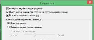
Now let's deal with the interface of the program. As you already understood, there are no settings in it, but there are plenty of icons for programming, and each of them carries a command in the Arduino IDE text format. There are even more icons in new versions, so it is difficult to deal with the latest version of ArduBlok and some of the icons are not translated into Russian.

In the section "Management" we will find a variety of cycles.

In the "Ports" section, we can manage the values of the ports, as well as the sound emitters, servos or ultrasonic proximity sensors connected to them.

In the "Numbers / Constants" section, we can choose digital values or create a variable, but you are unlikely to use the one below.

In the "Operators" section, we will find all the necessary comparison and calculation operators.

The Utilities section mostly uses icons over time.

"TinkerKit Bloks" is the section for purchased TinkerKit sensors. Of course, we don’t have such a set, but this does not mean that the icons will not work for other sets, on the contrary, it is very convenient for the guys to use icons such as turning on an LED or a button. These signs are used in almost all programs. But they have a peculiarity - when they are selected, there are incorrect icons indicating ports, so they must be removed and the icon from the “numbers / constants” section should be replaced at the top in the list.

"DF Robot" - this section is used if there are sensors specified in it, they are sometimes found. And our today's example is no exception, we have "Adjustable IR Switch" and "Line Sensor". The "line sensor" is different from the one in the picture, as it is from Amperka. Their actions are identical, but the sensor from Amperka is much better, since it has a sensitivity regulator.

Seeedstudio Grove - I have never used the sensors of this section, although there are only joysticks. This section has been expanded in new versions.

And the last section is "Linker Kit". The sensors presented in it did not come across to me.
I would like to show an example of a program on a robot moving along the strip. The robot is very simple, both in assembly and in acquisition, but first things first. Let's start with its acquisition and assembly.
Here is the set of parts itself, everything was purchased on the Amperka website.

- AMP-B001 Motor Shield (2 channels, 2 A) 1 890 rubles
- AMP-B017 Troyka Shield RUB 1,690
- AMP-X053 Battery compartment 3×2 AA 1 60 RUB
- AMP-B018 Line sensor digital 2 580 RUB
- ROB0049 Two-wheel platform miniQ 1 1890 RUB
- SEN0019 Infrared obstacle sensor 1 390 RUB
- FIT0032 Mount for infrared obstacle sensor 1 90 RUB
- A000066 Arduino Uno 1 1150 RUB

To begin with, we will assemble the wheeled platform and solder the wires to the engines.

Then we will install racks to mount the Arduino UNO board, which were taken from the old motherboard or other similar mounts.

Then we attach the Arduino UNO board to these racks, but we can’t fasten one bolt - the connectors get in the way. You can, of course, solder them, but it's up to you.

Next, we attach the infrared obstacle sensor to its special mount. Please note that the sensitivity control is on top, this is for ease of adjustment.


Now we install digital line sensors, here we have to look for a couple of bolts and 4 nuts for them. We install two nuts between the platform itself and the line sensor, and fix the sensors with the rest.

The next install Motor Shield or in another way you can call the motor driver. In our case, pay attention to the jumper. We will not be using a separate power supply for the motors, so it is installed in this position. The lower part is sealed with electrical tape, so that there are no accidental short circuits from the USB connector of the Arduino UNO, just in case.


Install Troyka Shield on top of Motor Shield. It is necessary for the convenience of connecting sensors. All the sensors we use are digital, so the line sensors are connected to ports 8 and 9, as they are also called pins, and the infrared obstacle sensor is connected to port 12. Be sure to note that you cannot use ports 4, 5, 6, 7 as they are used by the Motor Shield to control the motors. I even specially painted over these ports with a red marker so that the students could figure it out.

If you have already noticed, I added a black sleeve, just in case, so that the battery compartment we installed does not fly out. And finally, we fix the entire structure with an ordinary rubber band.
Battery compartment connections can be of 2 types. First wire connection to Troyka Shield. It is also possible to solder the power plug and connect it to the Arduino UNO board itself.


Here is our robot ready. Before you start programming, you will need to learn how everything works, namely:
- Motors:
Port 4 and 5 are used to control one motor, and 6 and 7 the other;
We adjust the rotation speed of the motors with PWM on ports 5 and 6;
Forward or backward by signaling ports 4 and 7.
- Sensors:
We are all digital, so they give logical signals in the form of 1 or 0;
And in order to adjust them, they have special regulators and with the help of a suitable screwdriver they can be calibrated.
Details can be found at Amperka. Why here? Because there is a lot of information on working with Arduino.
Well, we, perhaps, looked at everything superficially, studied and, of course, assembled the robot. Now it needs to be programmed, here it is - the long-awaited program!

And the program converted to Arduino IDE:
Void setup() ( pinMode(8 , INPUT); pinMode(12 , INPUT); pinMode(9 , INPUT); pinMode(4 , OUTPUT); pinMode(7 , OUTPUT); pinMode(5, OUTPUT); pinMode(6 , OUTPUT); ) void loop() ( if (digitalRead(12)) ( if (digitalRead(8)) ( if (digitalRead(9)) ( digitalWrite(4 , HIGH); analogWrite(5, 255); analogWrite( 6, 255); digitalWrite(7 , HIGH); ) else ( digitalWrite(4 , HIGH); analogWrite(5, 255); analogWrite(6, 50); digitalWrite(7 , LOW); ) ) else ( if (digitalRead (9)) ( digitalWrite(4 , LOW); analogWrite(5, 50); analogWrite(6, 255); digitalWrite(7 , HIGH); ) else ( digitalWrite(4 , HIGH); analogWrite(5, 255); analogWrite(6, 255); digitalWrite(7 , HIGH); ) ) ) else ( digitalWrite(4 , HIGH); analogWrite(5, 0); analogWrite(6, 0); digitalWrite(7 , HIGH); ) )
In conclusion, I want to say that this program is just a godsend for education, even for self-study, it will help you learn the Arduino IDE commands. The most important highlight is that with more than 50 installation icons, it starts to "fail". Yes, indeed, this is a highlight, since constant programming only on ArduBlok will not teach you how to program in the Arduino IDE. The so-called "glitch" makes it possible to think and try to remember commands for precise debugging of programs.
I wish you success.
In recent years, programming and robotics circles have become extremely popular and are accessible even to elementary school students. This became possible thanks to the use of graphical programming environments, which, it should be noted, are actively used by large companies. To talk about graphical programming environments, we have selected three of the most popular of them.
Visuino is a free graphical environment that runs on Arduino-compatible Controllino industrial controllers (PLCs). It makes it possible to create complex automation systems and IoT (Internet of Things, Internet of Things) solutions, and this can be done simply by moving and connecting visual blocks. The software environment automatically generates code for industrial controllers.
So what needs to be done. Select components (modules) from the components panel and move them to the design area. Then they need to be connected and set up properties. This is done using the object inspector.
The advantages of Visuino include a large set of components for mathematical and logic functions, servos, displays, the Internet, etc.
When the PLC is programmed, the graphical environment prompts the available way to connect to the controller. It can be a serial port, Ethernet, Wi-Fi or GSM.
Finally, your project is ready: all controllers are registered, everything works. Now, by clicking on the Arduino logo located on the top panel, you will force Visuino to create codes for Arduino and open its development environment (Arduino IDE), through which you can already compile the code and download it to the PLC.
Advice. If the installed board does not match your Arduino, you can change it using the "Select Board" command.
This graphical programming environment was created in 2003 when a group of MIT Media Lab employees decided to develop a programming language that is accessible to absolutely everyone. As a result, after some time, Scratch was introduced to the public.
Most of all, perhaps, it looks like Lego. At least the principle is the same: it's an object-oriented environment in which programs are assembled from details, colorful and bright. These details can be moved, modified, made to interact in various ways. Scratch is based on blocks of commands, such as sensors, variables, movement, sound, operators, appearance, pen, control, etc. The built-in graphics editor makes it possible to draw any object. Less than five years after the creation of Scratch, the Scratch for Arduino project (abbreviated as S4A) was born, which allows you to program the Arduino PLC.
The advantages of the system include the fact that it is Russified and completely localized - anyone who wants to find a lot of data on it. In addition, work in this graphical environment is available even for elementary school students who are not yet too confident in reading.
Advice. For those new to Scratch, there is a special resource: https://scratch-ru.info.
When a person has already fully mastered Scratch, but has not yet grown up to Wiring, on which Arduino-compatible boards are programmed, it's time to advise him the ArduBloсk tool written in Java. It is especially good for those who are fond of robotics.
What is the difference? The fact is that Scratch does not know how to flash the Arduino, it only controls its PLC via USB. Thus, Arduino cannot work on its own, because it depends on the computer.
In fact, ArduBloсk is an intermediate stage between the children's Scratch and the quite professional, albeit affordable Visuino, because, like the latter, it has the ability to flash Arduino-compatible controllers.
Advice. Don't forget to install Java machine on your PC. It does not take a lot of time.
So, more graphical environments - good and different. May the Arduino be with you.
Photo: manufacturing companies, pixabay.com Are you into programming? Yes, I'm a programmer Yes, this is a very interesting thing I'm not addicted, but my child is Yes No, I'm not interested View results Loading ... Read also: Arduino: how to turn an LCD monitor into a thermometer
Mini-PC Raspberry Pi 3 Model B + can become the center of the "smart" home
Perhaps the developers of operating systems are right, considering the user the worst enemy and the most dangerous virus. And maybe they are wrong, they create their creations not for themselves, but for users. In a word, I don't know. But what I know for sure is that I want to see the S4A program working not only on Windows, but on Linux, and not only on the Debian distribution.
I start this process by downloading the Debian version from the developer site: http://seaside.citilab.eu/scratch/arduino. All downloaded files are located after the download is completed in the "Download" or "Downloads" folder. Archived files destined for Linux are unpacked by the archive manager. The file I downloaded from openSUSE has a deb extension, but using Ark, the same archive manager, it can be decompressed. In openSUSE with the KDE 4 graphical manager, it is enough to right-click on the file and select the "Extract to subfolder" drop-down menu item. As a result, a folder named S4A appears.
Let's look into it.
Rice. 5.1. Contents of the downloaded S4A folder
Two files with the tar.gz extension are subject to further unzipping.
Rice. 5.2. Drop-down menu for working with archived files
As a result, a series of files and a folder named "usr" appear next to the archives. From my experience with Linux, I know that this folder can contain files that, when installed, are located at /usr on the root file system. If you open this folder, then

Chapter 5. Arduino, Visual Programming
Indeed, in it you can see three more folders.
These three folders correspond to the sections that can be seen if you open the "Root Folder" section in the /usr directory in the file manager.
Rice. 5.4. Partitions of the usr directory of the filesystem
The contents of the previously downloaded bin, lib and share folders should, I believe, be placed in the folders noted above. But, of course, no one will allow a simple user to change something in the file system. Therefore, in the “System” section of the main menu, we find the “File Manager” item, which opens a new submenu, where there is “File Manager (with administrator rights)”. This manager will allow you to transfer all the necessary files to the operating system. Without inventing anything, opening folders in parallel in two explorers, just sequentially open the necessary (they are all named) folders until the files appear, and copy the files.

Chapter 5. Arduino, Visual Programming
Rice. 5.5. Porting program files to openSUSE
Particular attention should be paid to the share folder, because it has many subfolders, and the corresponding folders should be looked for in the file system.
After copying, you can try to find the program in the main menu. And, indeed, on the Applications tab in the Development section (I have another section called Other Programs), the S4A program appears. And you can even run it. But after a few mouse movements, it starts to hang ...
IN terminal, and openSUSE has a root terminal; on behalf of the superuser, having previously connected the Arduino module, we launch the program. And she works. Now it can be launched in the usual way.
IN other distributions of Linux, the operation is similar to those described above, the differences are not so significant. Although in Fedora 14 I simply changed the user by logging in as root, which, of course, you should not do, it made it easier to put everything in the right places.
Having installed the program in Linux, let's see, why did we install it?
First, the program works with the module, showing what is happening on the analog and digital inputs of the module. Which is already good. But this is not the main thing. The main thing, secondly, the program allows you to assemble the program, and not code in the Arduino language.
When the program starts to work, in the left window there are a number of elements that can be moved by picking up the mouse to the middle window - the working "assembly" field. Let's move the element called Start.

Chapter 5. Arduino, Visual Programming
Rice. 5.6. Transferring the desired program elements
Now, by pressing the key labeled "control" in the box just above, we get a number of new elements.
Rice. 5.7. List of elements in the "Control" group
Among these elements, we will select the “always” element, which we will transfer to the existing element, and add it so that the upper cutout enters the ledge.

Chapter 5. Arduino, Visual Programming
Rice. 5.8. Adding elements to the program
Let's return to the set of elements we started with by pressing the "move" key and select the "digital 13 on" element, which we will move and put inside the previous one.
Rice. 5.9. Digital output enable command
From the “control” element set, we will take the “wait 1 second” element, which we will insert inside the “always” element under the “digital 13 on” element. To speed up this process, insert the wait element again, go back to the movement elements and add a "digital 13 off" element between the two wait elements.
Rice. 5.10. Blink program in graphical form
Does this design remind you of anything? When we started to describe the first program in ordinary language, we wrote it down like that.
Double click on the "start" element with the left mouse button and look at the Arduino module
The LED on pin 13, which has been silent so far, flashes regularly once a second.
We compiled the program, ran it and made the module work according to this program. And we didn't write a single line of code. It is for this reason that I prefer to distinguish between programming and writing code.

Chapter 5. Arduino, Visual Programming
But maybe it is the previously downloaded program that works, and not the one we have assembled?
Stop the program by double-clicking on the “start” element again. Let's left-click on the unit of the "wait 1 second" element.
Rice. 5.11. Changing Program Element Settings
Let's type in the number 5 (as on the bottom element). Let's run the program... and make sure we didn't confuse anything, the LED blinks every 5 seconds!
We have not tested the operation of the digital input in a "live" form. Isn't it time to do it?
Let's build the program in S4A. The first "bricks" are the same as in the previous program. Next ... we need to fulfill the condition: if the button is pressed, turn on the LED, otherwise turn it off. There is such an element - it is "if ... or ...". In its upper part there is a "nest" where you can insert the condition we need "digital input ...".
Rice. 5.12. Adding a condition to the if element of a program branch
It remains to add actions to get the desired type of program.
Rice. 5.13. The final formation of the program
If we compare it with a program written in the Arduino language, then we can say that the only differences are those that were made consciously: when the button is released, the LED does not light up, when it is pressed, the LED lights up.

Chapter 5. Arduino, Visual Programming
It's time to move on to checking. But first, a little warning.
In the diagram shown in the examples, the button is connected to the +5 V pin. I would advise turning it on a little differently.
Especially if you check everything "on weight". In case of a random error, it can turn out the way I did, smoke will come out of the module, which will spoil the mood very much. And the most correct way is to use a breadboard with adapters (for the Arduino Nano, I think there is a suitable socket for the microcircuit).
After checking the correct connections on the breadboard, connecting the Arduino module to it, you can plug it into the computer's USB connector and run the S4A program. Please note that when you connected a 10 kΩ resistor between the digital input and ground, the readings (in the right window of the program) stopped randomly changing between “false, false” and “true, true”. We launch our program by double-clicking on the “start” element, add, by going to the “Edit” section of the main menu, step-by-step execution.
Rice. 5.14. Add stepping to a debug routine
You can also select the execution speed in the "set a single step ..." item. And now, while the button is not pressed, we see that the LED is off, and the program is executed only in the part where it is set.

Chapter 5. Arduino, Visual Programming
Rice. 5.15. Running the program in debug mode
In the upper right window, you can see the status of the Digital1 input - false. The input is on the ground, the input is a low logical level, and this, from the point of view of the program, is a "false" state. Let's press the button.
Rice. 5.16. Program operation when the button is pressed
The state of the input "true" has changed, the LED is on, and the program enters the part where the condition is met.
If you pay attention to the orange elements in the "control" section, you can see that many of the
![]()
Chapter 5. Arduino, Visual Programming
they have "nests" for inserting conditions.
Conditions may vary. Above, we have used a change in the status of a digital input as a condition. But there may be other conditions as well.
Rice. 5.17. Nests for adding conditions in controls
And one more thing - pay attention to the black arrows "down" next to many elements.
Click this arrow with the mouse...
Rice. 5.18. An arrow that opens a list of possible sensors
And we get the opportunity to change, for example, as in this case the input used. In other cases, say, an output pin or an analog input changes. We have a wide range of options for experimenting with the Arduino module. However, why with the module? We may use multiple modules. Enough, not to say that this is the only way, go to the "suits" tab, right-click on the existing "suit" and select the "switch to new object" section.
Another Arduino module will appear. If you have it, if you connected it to a USB port, then you can, I think, work with it too.

Chapter 5. Arduino, Visual Programming
Rice. 5.19. Adding a Second Arduino Module
And the last remark. Everything we do in the S4A program, we do using the Scratch programming language. How do you like this?
Ardublock
Graphic Programming Language for Arduino
Ardublock Kit Ver 1.0 User Manual

What is Ardublock
Ardublock is a graphical programming language for Arduino designed for non-programmers and easy to use.
(remember that the program in the Arduino IDE is called a sketch)

Installation
Download the archive ardublock-all.jar
Open “Arduino IDE/Menu /Arduino/ Preferences”, there you will find the line “Sketchbook location”

3. Create a folder “tools/ArduBlockTool/tool” inside the “Arduino” folder in the line
“Sketch location” and copy the archive “ardublock-all.jar” to the “tool” folder.
If the username is “abu,”
On a Mac, /Users/abu/Documents/Arduino/tools/ArduBlockTool/tool/ardublock-all.jar
On Linux, /home/abu/sketchbook/tools/ArduBlockTool/tool/ardublock-all.jar
On Windows, C:\Users\abu\Documents\Arduino
4 Restart the Arduino IDE and you should have the “ArduBlock” item in the “Tool” menu.
Pay attention to the spelling of folder names in uppercase and lowercase letters.

Usage
ArduBlock blocks are divided into several categories.
control
Blocks of the “Control” category are control blocks.

Numbers, Constants and Variables

Operators

Utilities
These blocks are functions that are commonly used in sketches.

bricks
Each block in this category depicts a type of real device that you can directly connect to your sketch.

Pin
These blocks act as virtual pins on the Arduino board.

How to Program
1. Compilation should complete successfully. If the port specified in the Arduino environment or the board itself is not found, an error window appears.

2. Graphic units with connectors of the same shape can be connected to each other.
The connection is established simply, for this you need to drag one block to the one with which you want to connect it.
3. As soon as the “upload” button is pressed, ArduBlock will automatically generate the Arduino code, which will then be uploaded to the Arduino board (in this case, the text of the program obtained during the compilation will appear in the sketch window of the Arduino development environment).
How to run the program
simple derivation
1 Example 1 - Hello World (Hello World!)
1.1 Hardware connection
Arduino is connected to pin 13.
1.2 Operation
The LED will flash 1 time per second.
1.3 Sketch
1.4 Download
Note
You can download the abp file directly - all the examples described here can be downloaded along with the Ardublock environment description file (in English) as abp graphics sketch files.
The abp file can be loaded by clicking on the "load" button.

Then you need to specify the downloaded file and click the "open" button.


2 Example 2 - Alarm
2.1 Hardware connection
Digital Blue LED Light Module connects to pin 12.
2.2 Operation
The red LED and the blue LED will light up in turn like a police siren. The effect will be even better if you cover them with a translucent lid, or a cloth.
2.3 Sketch
2.4 Download
Simple input
3 Turns on the LED when a button is pressed
3.1 Hardware connection
Digital White LED Light Module is connected to pin 13.
3.2 Operation
If the button is pressed, the LED lights up.
3.3 Sketch

3.4 Download
4 Morse code
4.1 Hardware connection
Digital RED LED Light Module is connected to pin 13.
Digital Buzzer Module is connected to pin 12.
Digital Push Button is connected to pin 8.
4.2 Operation
When the button is pressed, the red LED lights up and a sound is heard. The sound period is similar to Morse code.
4.3 Sketch

4.4 Download
Analog input and output
5 Rotation sensor
5.1 Hardware settings
Analog Rotation Sensor V1 is connected to pin A0.
5.2 Operation
In this program, you can find out the value of the angle of rotation.
When you download the program, you can switch to arduino IDE, click on the monitor icon. The serial monitor windows will show you the rotation angle in values from 0 to 1023.
5.3 Sketch

5.4 Download
6 Fading light
6.1 Hardware settings
Digital White LED Light Module is connected to pin 11.
6.2 Operation
This program will show you how the light goes on and off slowly.
6.3 Sketch

6.4 Download
7 Noise measurement 1
7.1 Hardware settings
Digital White LED Light Module is connected to pin 11.
7.2 Operation
This detector can measure the ambient noise level, the LED will glow stronger if the sound is louder.
7.3 Sketch

7.4 Download
8 Noise measurement 2
8.1 Hardware settings
Digital White LED Light Module is connected to pin 11.
Analog Sound Sensor is connected to pin A0.
8.2 Operation
This detector can measure the ambient noise level, the LED will flash faster if the sound is louder.
8.3 Sketch

8.4 Download