With the help of Arduino. But what if we decide to manage devices connected to the household network? Let me remind you that even a small table lamp is powered by an alternating current source with a voltage of 220 volts. The conventional field effect transistor that we used in the circuit with the motor is no longer suitable.
To control a powerful load and even with alternating current, we use a relay. This is an electromechanical device that mechanically closes the load circuit using an electromagnet. Let's look at the insides:
The principle of operation of the relay is as follows. We apply voltage to the electromagnetic coil. A field appears in the coil that attracts a metal foot. In turn, the foot mechanically closes the load contacts.

Relays have two main uses. Firstly, we can supply only 5 volts to the coil, close the circuit of a very powerful load. For example, the relay used in lessons for Arduino may turn on a refrigerator or a washing machine. Secondly, some types of relays can simultaneously close and open several different circuits with different voltages at once.
In this lesson, we will not work with a separate relay, but with an entire relay module. In addition to the relay itself, the module also contains an optoelectronic isolation with a transistor, which protects the Arduino leads from power surges on the coil. 
A single relay module has only three contacts. Connect them as follows.
By the way, the relay input is inverted. This means that a high level on the contact In will turn off the relay coil, and a low level will turn it on.
Circuit diagram

Appearance of the layout

2. Program for Arduino
We will write a simple program that will turn on the lamp for 3 seconds and then turn off for 1 second.
Const int relPin \u003d 3; void setup () (pinMode (relPin, OUTPUT);) void loop () (digitalWrite (relPin, HIGH); delay (1000); digitalWrite (relPin, LOW); delay (3000);)
Download the program to Arduino. Now we connect the power to the lamp and to the relay. Finally, we supply power to the controller.

3. Auto light or street lamp
Using a controller, relay and light sensor, you can make a simple automatic lamp. The controller will light the lamp when the light level on the sensor becomes less than the set value.
As a sensor, we use a ready-made module based on. We will connect all three devices as follows.
Circuit diagram

Appearance of the layout

4. Auto lamp program
The analog output of the sensor gives values \u200b\u200bin the range from 0 to 1023. Moreover, 0 for the maximum level of light and 1023 for complete darkness.
First, we need to decide at what level of light to turn on the lamp, and at what to turn off. In our laboratory, in daylight, the sensor shows the value L \u003d 120, and at night it is about L \u003d 700. We will turn on the relay at L\u003e 600, and turn it off at L< 200. Вспомним как и напишем программу.
Const int photoPin \u003d A5; const int relPin \u003d 3; void setup () (pinMode (photoPin, INPUT); pinMode (relPin, OUTPUT);) void loop () (if (analogRead (photoPin)< 200) digitalWrite(relPin, HIGH); if(analogRead(photoPin) > 600) digitalWrite (relPin, LOW); )
We load the program on Arduino and conduct an experiment. This is best done at night.
Tasks
1. Music relay. As you know, an electromechanical relay makes a click when triggered. Try using this to play some simple melody.
2. Engine management. Having two three-pin relays, the same as in this lesson, you can assemble a circuit to change the direction of rotation of the motor.
It is not possible to connect a powerful load directly to the Arduino, for example, a lighting lamp or an electric pump. The microcontroller does not provide the necessary power to operate such a load. The current that can flow through the Arduino outputs does not exceed 10-15 mA. A relay comes to the rescue, with which you can switch a large current. In addition, if the load is powered by alternating current, for example 220v, then you can’t do without a relay at all. To connect powerful loads to Arduino via relays, relay modules are usually used.
Depending on the number of switched loads, one, two, three, four or more channel relay modules are used.
I bought my own, one and four channel modules on Aliexpress, for $ 0.5 and $ 2.09 respectively.
Module relay device for Arduino, using the 4-channel HL-54S V1.0 module as an example.
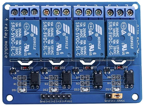
Let us consider in more detail the device of this module; according to this scheme, all multi-channel modules are usually built.

Module schematic.
To protect the Arduino terminals from power surges in the relay coil, a J3Y transistor and an 817C optocoupler are used. Please note the signal from the pin In fed to the cathode of the optocoupler. This means that in order for the relay to close the contacts, you need to apply to the pinIn logical 0 (inverted signal).

There are also modules in which the signal from the pin In fed to the anode of the optocoupler. In this case, you need to filelogical 1 per pinIn, to activate the relay.
The load power that the modules can enable / disable is limited by the relays installed on the board.

In this case, electromechanical relays are used. Songle SRD-05VDC-SL-Chaving the following characteristics:
Working voltage: 5 v
Coil Current: 71 mA
Maximum switching current: 10A
Maximum Switched DC Voltage: 28 V
Maximum Switched AC Voltage: 250 V
Operating temperature: -25 to + 70 ° C
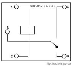
The Songle SRD-05VDC-SL-C relay has 5 pins. 1 and 2 relay power. Contact group 3 and 4 are normally open contacts ( NO), contact group 3 and 5 - normally closed ( NC).
Such relays are available for different voltages: 3, 5, 6, 9, 12, 24, 48 V. In this case, the 5-volt version is used, which allows you to power the relay module directly from Arduino.
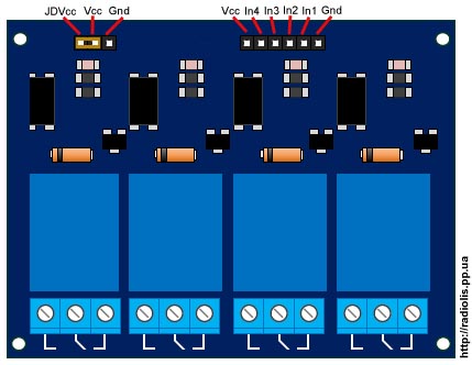
There is a jumper on the board ( Jdvcc), to power the relay either from Arduino, or from a separate power source.
Pinami In1, In2, In3, In4 the module connects to the Arduino digital pins.
Connection of the relay of the HL-54S V1.0 module to Arduino.

Since we have a module with 5-volt relays, we will connect it according to this scheme, we will take power from Arduino itself. In the example, I will connect one relay, I will use a 220 V bulb as a load.
To power the module relay from Arduino, the jumper must close the pins " Vcc"And" Jdvcc", Usually by default it is installed there.
If your relay is not 5 volts, you cannot power the module from Arduino, you need to take power from a separate source.
The diagram below shows how to connect the module power from a separate source. According to this scheme, you need to connect a relay that is powered by more or less than 5 V. For 5-volt relays, this circuit will also be more preferable.

With this connection you need to remove the jumper between the pins " Vcc"And" Jdvcc". Next pin JdvccConnect to + "External power supply, pin" GndConnect to - "Power source. Pin " Gnd", Which in the previous diagram was connected to the pin" Gnd»Arduino, in this circuit is not connected. In my example, an external 5 V power supply, if your relay is designed for a different voltage (3, 12, 24 V), select the appropriate external power.
Sketch for controlling a relay module through Arduino.
Fill the sketch in Arduino, which will turn on and off the light bulb (flasher).
| int relayPin \u003d 7; void setup () ( void loop () ( |
In line int relayPin \u003d 7; specify the number of the Arduino digital pin to which the pin was connected In1
module relay. You can connect to any digital pin and specify it in this line.
In line delay (5000); You can change the time at which the light will be on and at which it will be off.
In line digitalWrite (relayPin, LOW); indicated when supplying a logical zero ( Low), the relay module will close the contacts and the light will be on.
In line digitalWrite (relayPin, HIGH); indicated when supplying a logical unit ( High), the relay module will open the contacts and the light will go out.
As you can see, in the line digitalWrite (relayPin, LOW); left parameter Low. If the relay closes the contacts and the lamp lights up, it means a pin In1 you need to feed a logical zero, like mine. If the light does not come on, fill in the sketch in which we replace the parameter Low on HIGH.
The result of the sketch on the video.
Now let's add a clock button to the circuit and when you click on it, the relay module will turn on the light.

We connect the button together with a 10k pull-up resistor, which will not allow external interference to affect the operation of the circuit.

Fill the sketch
In line if (digitalRead (14) \u003d\u003d HIGH) set the number of the digital pin on which the button is connected. You can connect to any free one. In the example, this analog pinA0, it can also be used as a digital 14 pin.
In line delay (300);the value in milliseconds is specified. This value indicates how long after pressing or releasing the button, you need to perform actions. This is protection against contact bounce.
For information! All analog inputsfrom A0 ( numbered as 14) toA5 (19), can be used as digital (Digital PWM).
In conclusion, the result of the sketch on the video.
Cheaper relay modules may not contain an optocoupler in their circuit, as for example, in my case with a single-channel module.

Single Channel Relay Module Diagram. The manufacturer saved on an optocoupler, which is why the Arduino board lost galvanic isolation. For the operation of such a board, per pin In need to submit a logical zero.
Connecting the module relay to Arduino Due.
Arduino Due works from 3.3 volts, this is the maximum voltage that can be on its inputs / outputs. If there is a higher voltage, the board may burn out.
The question arises, how to connect the module to the relay?

We remove the jumper JDVcc. We connect a pin " Vcc»On the module relay board to the pin "3.3VArduino. If the relay is designed for 5 volts, connect pin " GND"Module relay boards, with pin" GNDArduino Due. Pin " Jdvcc"Connect to the pin" 5V”On the Arduino Due. If the relay is designed for a different voltage, then connect the power to the relay as in the figure, in the example it is 5 volts. If you have a multi-channel relay module, please check that « JDVcc » connected to one side of all relays. The optocoupler is activated by a 3.3 V signal, which in turn activates the transistor used to turn on the relay.
Solid-state relay from a triac for switching a powerful load through Arduino
4 Channel Relay Block Shield for Arduino UNO R3 and MEGA 2560
Relays are electromechanical devices that make and / or open contacts of an external electrical circuit when a control current is applied to the relay coil. This current generates a magnetic field, causing the ferromagnetic armature of the relay to move mechanically connected to the electrical contacts of the external electrical circuit. Subsequent movement of the contacts commutes this circuit.
You can connect a light bulb, fan, solenoid valve to the relay to control irrigation and programmatically control these devices by changing the state on the Arduino digital pins.
Relay Shield is an expansion board for Arduino, on which there are 4 independent TIANBO relays connected to Arduino digital pins. This relay is controlled by a voltage of 5 volts and is capable of switching up to 3 amps of a direct current of 24 V and an alternating current of 125 V.
To control 4 relays of the board, the following Arduino pins are used - D4, D5, D6, D7 .. When each Arduino pin is connected to the relay switching circuit, galvanic isolation is used, which prevents external interference when switching on / off connected to the load relay. The relay circuit uses a p-n-p type transistor, to open it you need to apply minus to the base. To do this, use the digitalWrite (pin, LOW) function. The transistor will be open and current will flow through the control circuit and the relay will trip. To turn off the relay, close the transistor by applying plus to the base by calling the digitalWrite (pin, HIGH) function.
The current state of each of them can be judged by the indicator LEDs located on the board. Each relay has a 3-wire terminal block, which allows the relay to be used both in the normally open mode and in the normally closed mode.
Unlike most relay modules for Arduino, this board is made in a shield format, which significantly saves space and increases the reliability of contact between Arduino and the relay.
Relay characteristics
Winding Current: 80 mA;
Maximum switching voltage: 24 V DC; 125 V of alternating current;
Maximum switched current: 3 A;
Recommended switching frequency: up to 1 Hz;
Lifetime: At least 50,000 shifts.
Consider an example using Relay Shield. We connect a lighting lamp to the relay, which will turn on / off depending on the illumination of the room. We will use a photoresistor as a room light sensor. Connection diagram.

// Used pin for relay
#define PIN_RELAY 7
// Pin connecting the photoresistor
#define PIN_PHOTORESISTOR A0
// variable for storing photoresistor readings
int val_photo;
// limit value of illumination
#define VAL_PHOTO_ON 220
#define VAL_PHOTO_OFF 520
Void setup (void)
{
// serial port connection
Serial.begin (9600);
// configure relay output as OUTPUT
pinMode (PIN_RELAY, OUTPUT);
// turn on the light
digitalWrite (PIN_RELAY, LOW);
}
void loop (void)
{
// receive data from the photoresistor
val_photo \u003d analogRead (PIN_PHOTORESISTOR);
// enable
if (val_photo< VAL_PHOTO_ON)
digitalWrite (PIN_RELAY, LOW);
// turn off
else if (val_photo< VAL_PHOTO_OFF)
digitalWrite (PIN_RELAY, HIGH);
// pause before the next measurement
delay (5000);
To switch various power equipment and other devices using a relatively small voltage, a relay is used. In the classic version, the simplest relay consists of a coil to which control voltage is applied, and a contact that closes or opens the control object circuit. In addition to the control function, the relays also provide protection for the control circuit due to galvanic isolation, since there is a gap between the coil and the contact, which does not allow voltage to flow from one circuit to another. Novice hams, who may have recently met with the currently popular Arduino board, are interested in using relays in their projects, but do not know where to start.
Therefore, this material shows the ease of use of Arduino and relays. First of all, it is designed for beginners who get acquainted with Arduino and collect on the basis of this board.
To create a relay circuit, we need an Arduino, one resistor per 1 KOhm, one resistor 10 KOhm, one transistor BC547, one relay 6 V or 12 V, one diode 1N4007, and we take a 12 V fan as a control object. :

After pressing the button, the fan should turn on and rotate until the button is pressed again. Sketch for such an algorithm:
int pinButton \u003d 8; int Relay \u003d 2; int stateRelay \u003d LOW; int stateButton; int previous \u003d LOW; long time \u003d 0; long debounce \u003d 500; void setup () (pinMode (pinButton, INPUT); pinMode (Relay, OUTPUT);) void loop () (stateButton \u003d digitalRead (pinButton); if (stateButton \u003d\u003d HIGH && previous \u003d\u003d LOW && millis () - time\u003e debounce) (if (stateRelay \u003d\u003d HIGH) (stateRelay \u003d LOW;) else (stateRelay \u003d HIGH;) time \u003d millis ();) digitalWrite (Relay, stateRelay); previous \u003d\u003d stateButton;)
So how does our circuit work? After pressing the button, the Arduino will transfer pin 2 to a high logical state, that is, the output will have a voltage of 5 V. This voltage is used to open the transistor, which will turn on the relay, after which our load (in this case, the fan) will be powered by the main power source.
You cannot use the 5V USB port to power the transistor and load, as there will not be enough current. Therefore, you need to use an external Vcc power supply with a voltage of 7-12 V to power both the Arduino and the transistor-relay circuit. The load uses its power source. You can, for example, use a lamp as a load and power it from 220 V. And in no case do not connect the Arduino power and the load power!
Now let's complicate our program a bit by adding a delay when the relay is turned off. The stayON variable here will be used to set the delay period in milliseconds (5 seconds by default). As a result, after pressing the button, the relay will turn on and after 5 seconds it will turn off. Code:
int pinButton \u003d 8; int Relay \u003d 2; int stateRelay \u003d LOW; int stateButton; int previous \u003d LOW; long time \u003d 0; long debounce \u003d 500; int stayON \u003d 5000; // 5000 ms delay void setup () (pinMode (pinButton, INPUT); pinMode (Relay, OUTPUT);) void loop () (stateButton \u003d digitalRead (pinButton); if (stateButton \u003d\u003d HIGH && previous \u003d\u003d LOW && millis () - time\u003e debounce) (if (stateRelay \u003d\u003d HIGH) (digitalWrite (Relay, LOW);) else (digitalWrite (Relay, HIGH); delay (stayON); digitalWrite (Relay, LOW);) time \u003d millis ();) previous \u003d\u003d stateButton;)
Now, thanks to the information in this example, you can safely add relays to your new projects with Arduino.
Another fan control circuit using Arduino is possible.
Arduno relay allows you to connect devices operating in modes with relatively high currents or voltages. We cannot directly connect powerful pumps, motors, even an ordinary incandescent bulb to the Arduino board - the board is not designed for such a load and will not work. That is why we will have to add a relay to the circuit, which you can find in any project. In this article we will talk about what relays are, what they are, how you can connect them to your arduino project.
A relay is a gateway that allows you to connect together electrical circuits with completely different parameters. An ordinary lock on the river connects water channels located at different heights, opening or closing gates. The relay in arduino turns on or off external devices, in a certain way closing or disconnecting the separate electrical network into which they are connected. With the help of arduino and relays, we control the process of turning on or off the same way we turn the lights on or off at home - giving a command to close or open. Arduino gives a signal, the very closure or opening of the “powerful” circuit will make the relay through special internal mechanisms. The relay can be imagined as a remote control, with which we perform the necessary actions using relatively “weak” signals.
The relay is characterized by the following parameters:
- Voltage or tripping current.
- Voltage or release current.
- Response and release times.
- Working current and voltage.
- Internal resistance.
Depending on the type of these internal disconnecting mechanisms and device features, two main relay groups can be distinguished: electromechanical relays (switching by means of an electromagnet) and solid state relays (switching through special semiconductor components).
Electromagnetic and solid state relays
Electromagnetic relay
 An electromagnetic relay is an electrical device that mechanically closes or opens the load circuit using a magnet. consists of an electromagnet, a movable armature and a switch. An electromagnet is a wire that is wound on a coil of a ferromagnet. An anchor is a plate of magnetic material. In some models of the device, additional electronic components can be built in: a resistor for more accurate relay operation, a capacitor to reduce interference, a diode to eliminate overvoltages.
The relay operates due to the electromagnetic force that occurs in the cores when current is supplied through the turns of the coil. In the initial state, the spring holds the anchor. When a control signal is supplied, the magnet begins to attract the armature and to close or open the circuit. When the voltage is turned off, the armature returns to its initial position. Sources of control voltage can be sensors (pressure, temperature, etc.), electrical circuits, and other devices that supply low current or low voltage.
An electromagnetic relay is used in automation circuits, when controlling various technological installations, electric drives and other devices. The relay is designed to regulate voltages and currents, can be used as a storage or converting device, and can also record deviations of parameters from normal values.
Classification of electromagnetic relays:
- The control current can be either constant or variable. In the first case, the device may be neutral or polarized. For alternating current, the armature is made of electrical steel to reduce losses.
- Anchor or reed relay. For the anchor, the process of closing and opening occurs by moving the armature, for the reed switch the absence of a core is characteristic, the magnetic field acts on the electrode with contacts.
- Speed \u200b\u200b- up to 50 ms, up to 150 ms and from 1 s.
- Protective coating - sealed, sheathed and open.
Compared with semiconductor devices, an electromagnetic relay has advantages - it is inexpensive, switching a large load with a small size of the device, low heat generation on the coil. Among the shortcomings can be distinguished slow response, interference and the complexity of switching inductive loads.
Solid state relays
 Solid state relays are considered a good alternative to electromagnetic relays; they are a modular semiconductor device, which is manufactured using hybrid technology. The relay contains transistors, triacs or thyristors. Compared to electromagnetic devices, solid state relays have several advantages:
- Long service life.
- Performance.
- Small sizes.
- There are no extraneous noise, acoustic noise, contact bounce.
- Low power consumption.
- Quality insulation.
- Resistance to vibration and shock.
- There is no arc discharge, which allows you to work in explosive places.
They work according to the following principle: a control signal is supplied to the LED, galvanic isolation of the control and switched circuits takes place, then the signal passes to the photodiode array. The voltage is regulated by a power switch.
Solid state relays also have several drawbacks. Firstly, when switching, the device heats up. Increasing the temperature of the device leads to a limitation of the regulated current - at temperatures exceeding 60 degrees, the current decreases, the maximum operating temperature is 80 degrees.
Solid state relays are classified according to the following criteria:
- Type of load - single-phase and three-phase.
- Way of control - switching occurs due to direct voltage, alternating or manual control.
- Switching method: zero-crossing control (used for weakly inductive, capacitive and resistive loads), random switching (inductive and resistive loads that require instantaneous operation) and phase control (change of output voltage, power regulation, control of incandescent lamps).
Relay in Arduino projects
The most common relay for the Arduino board is in the form of a module, for example, SONGLE SRD-05VDC. The device is controlled by a voltage of 5 V, can switch up to 10 A 30 V DC and 10 A 250 V AC.
The circuit is shown in the figure. The relay consists of two unconnected circuits - the control circuit A1 and A2 and the controlled circuit 1, 2 and 3.

Between A1 and A2 there is a metal core. If an electric current is launched through it, an anchor (2) will be attracted to it. 1, 3 - fixed contacts. In the absence of current, the armature will be near pin 3.
Relay connection to Arduino
Consider a single-channel relay module. It has only 3 contacts, they are connected to the Arduino Uno as follows: GND - GND, VCC - + 5V, In - 3. The relay input is inverted, so a high level on In turns off the coil, and low - turns it on.

LEDs are needed for indication - when the red LED1 lights up, voltage is applied to the relay, when the green LED2 lights up, it closes. When the microcontroller turns on, the transistor is closed. To open it, you need a minus to the base, it is served using the digitalWrite (pin, LOW); function. The transistor opens, current flows through the circuit, the relay trips. To turn it off, a plus is applied to the base using digitalWrite (pin, HIGH) ;.