Many people today use LED strip to illuminate a wide variety of interior elements in their homes. Moreover, often led backlight is located behind the TV. It is quite easy to organize such lighting with your own hands, if you know some of the nuances that we will talk about in this article.
The easiest way to organize this type of lighting is to use a regular LED strip or PaintPack. Our today's article will tell you about the advantages of TV backlighting with LED strip, as well as what the PaintPack system is for.
Why do you need a TV backlight
It is known that watching TV in complete darkness is very harmful to the human visual system. The negative effect is especially pronounced in adults, while in children it is smoothed out due to growth and development, as well as the strong regenerative abilities of the child's body.
Note! The harm in this situation is confirmed both by many studies and by the subjective feelings of people.
Watching TV without at least background lighting is fraught with a number of negative phenomena:
- rapid eye fatigue;
- drop in visual acuity;
- the appearance of headaches, etc.
Note! All this, especially rapid eye fatigue, is due to the presence of too bright and noticeable contrast between the TV screen and a darkened room. In addition, the brightness of the screen itself is capable of dynamically changing, which forces the human visual system to function in extreme conditions for itself.
A bright TV screen and a dark room are a bad combination for the eyes
Prolonged or even worse - constant TV viewing, when there is no background light, and the whole room is in darkness, leads to the development of stress, as well as general fatigue. Ultimately, there is a general decline in human health, deterioration of protective and adaptive mechanisms in his body.
The solution to the problem: outdoor lighting
To date, the problem of watching television at night has a fairly simple solution, which is implemented by hand. This solution lies in the installation of additional backlighting for those models that do not have the screen edge lighting provided by the manufacturer.
But here there are "pitfalls", without knowledge of which harm to the body will continue to be inflicted. In this situation, the following nuances must be taken into account:
- general ceiling illumination will not work here, since its luminous flux will illuminate the screen. As a result, the TV contrast will begin to decrease;

Room ceiling lighting
- a slightly better solution would be to use wall sconces, floor lamps and table lamps. But in such a situation, we are faced with the problem of optimal placement of lighting fixtures., because they should not interfere with TV viewing. If such lamps are located behind the viewer, they will create glare on the screen. And if you place them near the TV, then they will attract attention, distracting;

Lamp next to the TV
- background lighting. The creation of backlighting around the TV is devoid of all the disadvantages of the previously listed methods of placing lighting devices. The advantages of this method include the fact that lighting with the help of modern technologies (LED strips and PaintPack) can be easily organized with your own hands.
As you can see, backlighting is the best option in this situation.
Features of backlighting: what to consider
The background lighting, which is organized with your own hands behind the TV, must meet a number of requirements:
- be unobtrusive so as not to attract undue attention to yourself;
- to give an optimal level of light flux to prevent eye fatigue from prolonged viewing of TV programs at night;

Background lighting
- do it yourself easily and quickly;
- the light sources with which it is formed should not be heated. This factor can lead to the risk of a fire hazardous situation, since the TV itself, even modern models, heats up during its operation;
- luminaires used for backlighting must be environmentally friendly and not contain harmful substances. Such requirements are due to the fact that being placed behind equipment of this kind, they are at risk of mechanical damage. Especially if there are small children in the house who are constantly scurrying around the equipment.
Of the whole variety of lighting devices actively used in the system of outdoor and indoor lighting, in this situation, LED products are most fully suited to the above requirements, namely LED strips.
Benefits of LED TV lighting in the background
The use of an LED strip as a backlight for any equipment in the house has the following advantages:
- the ability to choose the backlight of any color. LED products are distinguished by a fairly wide range of all possible colors and shades;

Neon lights
- simple DIY installation. Due to the presence of a self-adhesive base, such products can be glued to any surface, even the back cover of equipment;
- excellent luminous flux, which is several times superior to all other light sources;
- lack of significant heating during operation;
- completely environmentally friendly products that cannot break and injure a child;
- low power consumption;
- long period of service.
Separately, it should be noted that as a decorative and background illumination of a TV, LED strip can give any room an atmosphere of celebration, romance or fabulousness.
With such advantages, it is not surprising that it is the LED strip that has become the most widely used as a backlight not only for TVs, but also for various decorative elements of the interior.
Options for installing LED backlight for TV
As we have already found out, the easiest and most affordable way to make backlighting with your own hands is to install an LED strip on the back of the TV. This procedure will not take you much time and will require the following steps:
- we put the TV on a table prepared in advance, which is covered with a cloth. This must be done carefully so as not to damage the screen;
- along the perimeter of the back cover with glue LED strip. Remember that it can have any glow color;
- since the TV will heat up during its operation, the tape should additionally be planted on glue every 5-10 cm;

Installing the Ribbon
- further in the corner we solder the strips of tape. Here you can buy special corner connectors;
- then we connect to them a power supply with the required power for the tape used in the backlight. The circuit will need to include a relay or a 5 → 12 volt converter. This is necessary if the device has USB outputs;

Connection diagram
- backlight switch can be attached in the corner.
Note! The tape must be firmly attached so as not to provoke a short circuit.

PaintPack system
In addition, PaintPack lighting systems can be used.
The PaintPack system is a small box. Removable LED strips are connected to it from both sides. PaintPack is also equipped with an indicator, a power connector and a microUSB through which it is possible to connect to a computer. Also included in PaintPack is a master connector. It can be used to connect two devices in series.
Note! This fixture is great for background lighting and computer monitors.
Install the system case on the back of the TV. Further, according to the above algorithm, we mount and connect the LED strips.
if you plan to connect PaintPack via USB to a computer, you will need to install the required drivers, as well as configure the device in the bundled program. For this you need the AmbiBox package.
Conclusion
When deciding to create a TV backlight, you will not find a better light source than an LED strip. In this situation, all manipulations are quite easy to do with your own hands, which is another plus. What's more, by using PaintPack, you can make your DIY backlight technology more technological.
 Lighting in the kitchen of a small apartment
TVs with dynamic backlighting around the display frame is one of the proprietary chips of Philips. And unlike many others, it works. Everything comes at a price, however, and TVs with Ambilight and immersive presence are more expensive than many others.
Russian developers have proposed a method that will equip monitors from any manufacturer with dynamic backlighting. To do this, you don't even have to take the device to a service center: it will only take a little time and perseverance.
In general, such a backlight can be purchased as radio components and configured independently. But, as practice shows, this is almost comparable to the ready-made options from PaintPack.
There are two main models available: a monitor version (30 LEDs) and a TV version (60 LEDs). There is also a very simple one - for 10 LEDs, but it is suitable only for the smallest monitors.
The TV version is equipped with an external power supply. Also, a larger number of LEDs speaks in its favor, which gives a larger illumination area (it will shine wider and higher, in other words). If such options are not suitable for any reason, you can contact the developers: for a small surcharge, they will offer a modified version.
mindrunway.ruPaintPack, in fact, is a small case, to which removable LED strips are connected from both sides. The box with the filling carries indicators and a power connector, as well as a microUSB for connecting to a PC. There is also a master connector (proprietary) for daisy chaining two devices.
The device body is located on the back of the TV or monitor. Then LED strips are laid in accordance with the instructions, power is connected and witchcraft begins. When connecting PaintPack to a computer via USB, you need to install drivers and configure the device in the bundled program.
 mysku.ru
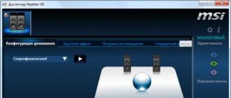
 The setting is done using the AmbiBox package. It is necessary to go to the "Intelligent backlight" menu, select a screen capture method and one of the operating modes offered in the program:
- Static background - any color can be set, LED glow is regulated.
- Color music - the backlight will flash in time with the sound of music. The backlight color is set to green-yellow.
- Dynamic background - smooth flow of one color into another.
- Screen capture is the main mode of operation.
In this mode, it is possible to capture color from the movies and games being watched. The backlight color will change according to the image on the screen, dividing into top, bottom and side zones (each separately).
PaintPack works a little slower than the official Philips counterpart. But taking into account the difference in cost and the possibility of upgrading any device, the choice is obvious.
Philips patented an incredibly simple, but without exaggeration, amazing TV backlight technology in 2007. With this adaptive backlight, less eye fatigue when viewing in the dark, increased presence, wider display area, etc. Ambilight is applicable not only to video and photo content, but also to games. Ambilight has become the hallmark of Philips TVs. Since then, Philips has been closely vigilant so that none of the major manufacturers dare to infringe upon the sacred by creating something like that. Probably, this technology can be licensed, but the conditions are outrageous, and other market players are not particularly eager to do this. Small companies also tried (and now there are companies that do) to implement similar technology in the form of separate kits, but the Philips car was inevitable. So at best, if the company does not somehow renew the patent or its derivative, other manufacturers will only be able to release something similar in 2027.
But for us, ordinary consumers, this punishment does not apply. We are free for ourselves to do what we deem necessary. Today I will tell you in detail how to make an adaptive backlight for a TV or monitor like Philips Ambilight (hereinafter simply Ambilight). For some, the article will not contain anything new in itself, tk. There are dozens of such projects, and hundreds of articles have been written in different languages, and there are thousands of people who have already done this for themselves. But for many, this can all be very interesting. You don't need any special skills. Only basic knowledge of physics for the 8th grade of high school. Well, and quite a bit of wire soldering.
So that you better understand what I am talking about, I will give my example of what happened. The real costs for TV 42 "are about 1000 rubles and 2 hours of work.
The video does not convey all the sensations and effect in full, but the children sat with their mouths open for the first time.
Possible implementation options
There are several options for implementing Ambilight. They depend on the video source.The cheapest, simplest and most effective option is a Windows PC, Mac OS X or Linux PC as a signal source. Nowadays, Windows-based boxes on Atom processors are very common, which cost from $ 70. They are all perfect for the Ambilight implementation. For several years now I have been using various Windows boxes (in a TV cabinet) as a media player, wrote a small handful of reviews and consider them to be the best TV boxes for media content. The hardware implementation of this option is the same for all the listed operating systems. It is about this option that I will talk about in the article... The software part will be related to the Windows system, AmbiBox will act as a universal control program. With Mac OS X and Linux can be used.
The second option - the source of the signal is an Android-based media attachment, of which there are also a huge number. This option is the most problematic. First, the highlighting will only work in the Kodi media combine (and offshoots of that project). Secondly, in the overwhelming majority of cases, everything works only with disabled hardware video decoding, which is unacceptable for most boxes. The hardware implementation of the project also imposes certain requirements. I will not touch on it, but if something interests specific, then I will try to answer in the comments.
The third option is a source-independent solution. This is the most expensive, but absolutely universal solution. the signal is taken directly from the HDMI cable. For it, you will need a sufficiently powerful microcomputer (like Raspberry Pi), HDMI splitter (splitter), HDMI-RCA AV converter, USB 2.0 analog video capture device. Only with this option you can be guaranteed to use Ambilight with any TV-set / receiver, Android-boxes, Apple TV, game consoles (for example, Xbox One, PlayStation 4), etc. devices that have HDMI output. For the variant with support for 1080p60, the cost of components (without LED strip) will be about $ 70, with support for 2160p60 - about $ 100. This option is very interesting, but you need to write a separate article on it.
Hardware part
To implement, you will need three main components: a controllable RGB LED strip, a power supply, an Arduino microcomputer.First, a few explanations.
WS2811 is a three-channel channel controller / driver (IC) for RGB LEDs with one-wire control (addressing to an arbitrary LED). The WS2812B is an RGB LED in the SMD 5050 package, which already has an integrated WS2811 controller.
LED strips suitable for the project are called WS2811 or WS2812B for simplicity.
WS2812B tape is a tape on which WS2812B LEDs are placed in series. The tape operates with a voltage of 5 V. There are tapes with different LED densities. Usually these are: 144, 90, 74, 60, 30 per meter. There are different degrees of protection. Most often these are: IP20-30 (protection against the ingress of solid particles), IP65 (protection against dust and water jets), IP67 (protection against dust and protection during partial or short-term immersion in water to a depth of 1 m). The backing is black and white.
Here's an example of such a tape:

WS2811 tape is a tape on which a WS2811 controller and some kind of RGB LED are placed in series. There are options for 5 V and 12 V. The density and protection are similar to the previous option.
Here's an example of such a tape:

There are also WS2811 "tapes" with large and powerful LEDs, as in the photo below. They are also suitable for implementing Ambilight for some huge panel.

Which tape to choose, WS2812B and WS2811?
An important factor is the feed of the tape, which I will talk about a little later.
If you have a suitable power supply unit at home (often power supplies remain from old or damaged equipment at home), then choose a tape based on the voltage of the power supply, i.e. 5V - WS2812B, 12V - WS2811. In this case, you will simply save money.
From myself I can give a recommendation. If the total number of LEDs in the system is no more than 120, then WS2812B. If more than 120, then WS2811 with an operating voltage of 12 V. Why this is so, you will understand when it comes to connecting the tape to the power supply.
What level of tape protection should I choose?
For most, IP65 is suitable, because on one side it is coated with "silicone" (epoxy resin) and on the other there is a 3M self-adhesive surface. This tape is convenient to mount on a TV or monitor and is convenient to wipe off dust.
Which LED Density to Choose?
For the project, tapes with a density of 30 to 60 LEDs per meter are suitable (of course, 144 is possible, no one forbids). The higher the density, the higher the Ambilight resolution (number of zones) and the higher the maximum overall brightness. But it should be borne in mind that the more LEDs in the project, the more complex the tape power circuit will be, and a more powerful power supply will be needed. The maximum number of LEDs in a project is 300.
Buying tape
If your TV or monitor is hanging on a wall and all 4 sides have a lot of free space side by side, then the tape is best placed at the back around the perimeter on all 4 sides for maximum effect. If your TV or monitor is installed on a stand, or there is little free space at the bottom, then the tape should be placed on the back on 3 sides (i.e. the bottom without tape).
For myself, I chose a white tape WS2812B IP65 with 30 LEDs per meter. I already had a suitable 5V power supply. I decided whether 60 or 30 LEDs per meter, but chose the latter after reviewing the video with ready-made examples of implementation - the brightness and resolution suited me, and the power is easier to organize, less wires. There is a huge number of WS2812B tapes on Aliexpress. I ordered 5 meters for $ 16. For my TV (42 ", 3 sides), I needed only 2 meters, that is, I could buy it for $ 10, the remaining three meters for a friend. Prices often change from sellers, there are many offers, so just choose a cheap lot on Aliexpress with a high rating (search keywords - WS2812B IP65 or WS2811 12V IP65).


Buying a power supply for tape
The power supply unit is selected according to power and voltage. For WS2812B - voltage 5 V. For WS2811 - 5 or 12 V. Maximum power consumption of one WS2812B LED is 0.3 W. For WS2811 in most cases it is the same. Those. the power of the power supply must be at least N * 0.3 W, where N is the number of LEDs in the project.
For example, you have a 42 "TV, you settled on a WS2812B tape with 30 LEDs per meter, you need 3 meters of tape on all 4 sides. You will need a 5 V power supply with a maximum power of 0.3 * 30 * 3 \u003d 27 W , i.e. 5 V / 6 A. In my implementation, only 3 sides are used, a total of 60 LEDs (to be precise, 57) - power from 18 W, i.e. 5 V / 4 A.
I have had an ORICO CSA-5U (8 A) multi-port USB charger idle for a long time, left over from the old review. The power of the ports is parallel to it (this is critically important), this memory is ideal for me as a power supply unit, since I will connect the tape through 2 parallel connections (explanations will be a little later in the article).

If I didn’t have this memory, I would have chosen (there is information that it is in this PSU that the internals are put at 2.5 A, so you need to study this issue in more detail from the seller, or look at other models).

Buying a microcomputer
Ambilight will be controlled by the Arduino microcomputer. Arduino Nano on Aliexpress costs about apiece.

Costs for my version (for TV 42 "):
$ 10 - 2 meters WS2812B IP65 (30 LEDs per meter)
$ 4 - power supply 5 V / 4 A (I did not spend money on the PSU, I quote the cost for clarity)
$ 2.5 - Arduino Nano
-----------
16,5$
or 1000 rubles
Hardware implementation
The most important thing is to properly organize the feed of the tape. The tape is long, the voltage sags at high current, especially at 5 V. Most of the problems that arise for those who make themselves Ambilight, are connected with the power supply. I use the rule - you need to make a separate power supply for every 10 W of maximum power consumption at 5 V and 25 W of power consumption at 12 V. The length of the power supply (from the power supply to the tape itself) should be minimal (no margin), especially at 5 IN.
The general connection diagram is as follows (the diagram shows the power connection for my version):

Power is supplied to the tape from both ends - two parallel connections. For example, if I did the backlight on all 4 sides, and the tape was 60 LEDs per meter (i.e., the maximum power is 54 W), then I would make the following power supply:

The supply wires must be used appropriate, the smaller the gauge (AWG), the better, so that they are sufficient for the calculated current strength.
There are two pins going to the Arduino from the tape. GND, which needs to be connected to the corresponding pin on the Arduino. And DATA, which needs to be connected to the sixth digital pin through a 300-550 Ohm resistor (preferably 470 Ohm). If you do not have a resistor, then in most cases everything will work fine without it, but it is better to have one. A resistor can be bought for a couple of kopecks at any radio store. The Arduino microcomputer itself can be placed in any convenient case, many use the Kinder surprise egg for this. The Arduino should be placed as close to the tape as possible so that the DATA leads are as short as possible.
Soldering wires to tape is simple. The main rule is that the time of contact with the soldering iron should be minimal, you cannot "poke around" with a soldering iron.
In my case, it turned out like this:


Two black high-quality USB cables went for power, and a white one for connecting to a computer. I ran out of white heat shrink tubing, I used red ones. Not so “pretty”, but it suits me (it's still hidden behind TV).
An important question is how to bend the tape at right angles? If you have a 60 LED strip, then the strip needs to be cut and connected with short wires (placing all this in a heat shrink tube). You can buy special angled connectors for three pins for LED strips (4 pins in the picture, just for example):

If you have a 30 LED strip, then the distance between the LEDs is large, you can easily make a corner without cutting. Remove a piece of the "silicone" coating, isolate (you can even "tape") the contact pad and bend it according to the scheme:
I cut off a piece of tape to practice. The main thing is not to overdo it - they slightly bent it once and that's it. You do not need to bend here and there, you do not need to squeeze the bend line strongly.

Here is the rear view of the TV, all the wires through the hole go into the cabinet:

Software part
This is the simplest.We connect the Arduino microcomputer via USB. The driver (CH340 serial interface) will be installed automatically. If this did not happen, then in the Arduino IDE folder there is a Drivers folder with everything you need.
Launch Arduino IDE and open the Adalight.ino file.

We change the number of LEDs in the code. I have 57.

Tools\u003e Board\u003e Arduino nano
Tools\u003e Port\u003e Select COM port (there will be the desired option)
Press the button "Download":

The program will inform you when the download is complete (this is literally a couple of seconds).
Done. You need to disconnect the Arduino from USB and reconnect. The ribbon will light up sequentially in red, green and blue - the Arduino is activated and ready to work.
Download and install the program. In the program, click "More settings" and specify the device - Adalight, COM port and the number of LEDs. Select the number of frames to capture (up to 60).

Next, click Show Capture Zones\u003e Zone Configuration Wizard. Select your ribbon configuration.

Click Apply and Save Settings. This concludes the basic settings. Then you can experiment with the size of the capture zones, color correction of the tape, etc. The program has many different settings.

To activate a profile, just double-click on the corresponding icon (AmbiBox profiles) in the Windows notification area. The tape will immediately light up. It also turns off by double clicking.
That's basically it. You saw the result at the beginning of the article. Nothing complicated, cheap and great. I'm sure you will do better, so share your crafts in the comments.
TVs with dynamic backlighting around the display frame is one of the proprietary chips of Philips. And unlike many others, it works. Everything comes at a price, however, and TVs with Ambilight and immersive presence are more expensive than many others.
Russian developers have proposed a method that will equip monitors from any manufacturer with dynamic backlighting. To do this, you don't even have to take the device to a service center: it will only take a little time and perseverance.
In general, such a backlight can be purchased as radio components and configured independently. But, as practice shows, this is almost comparable to the ready-made options from PaintPack.
There are two main models available: a monitor version (30 LEDs) and a TV version (60 LEDs). There is also a very simple one - for 10 LEDs, but it is suitable only for the smallest monitors.
The TV version is equipped with an external power supply. Also, a larger number of LEDs speaks in its favor, which gives a larger illumination area (it will shine wider and higher, in other words). If such options are not suitable for any reason, you can contact the developers: for a small surcharge, they will offer a modified version.
mindrunway.ruPaintPack, in fact, is a small case, to which removable LED strips are connected from both sides. The box with the filling carries indicators and a power connector, as well as a microUSB for connecting to a PC. There is also a master connector (proprietary) for daisy chaining two devices.
The device body is located on the back of the TV or monitor. Then LED strips are laid in accordance with the instructions, power is connected and witchcraft begins. When connecting PaintPack to a computer via USB, you need to install drivers and configure the device in the bundled program.
mysku.ru The setting is done using the AmbiBox package. It is necessary to go to the "Intelligent backlight" menu, select a screen capture method and one of the operating modes offered in the program:
- Static background - any color can be set, LED glow is regulated.
- Color music - the backlight will flash in time with the sound of music. The backlight color is set to green-yellow.
- Dynamic background - smooth flow of one color into another.
- Screen capture is the main mode of operation.
In this mode, it is possible to capture color from the movies and games being watched. The backlight color will change according to the image on the screen, dividing into top, bottom and side zones (each separately).
PaintPack works a little slower than the official Philips counterpart. But taking into account the difference in cost and the possibility of upgrading any device, the choice is obvious.
Backlit.
The option proposed below differs from those already discussed in that the backlight turns on automatically, does not require changes to the design of the TV and can work as an emergency lighting.
Among the shortcomings, it should be noted that the backlight is static, it takes time to install and configure for specific equipment.
Formulation of the problem
So, we need a backlight that turns on when the room is dark enough and the TV is turned on, it burns in half light when the TV is not working, but it is very dark in the room and someone is walking on it. In all other cases, the backlight must be off. Limitations: equipment under warranty - you cannot climb inside.Decision
To determine the operating mode of the TV, we will use this thing:TAK12-02 High-frequency Pulse Current Transformer
The device allows, by inserting one of the power wires into the hole, to remove the induced current from the contacts, and by its value to draw a conclusion about the operating mode of the TV. Suppose that for a TV in sleep mode, the current consumption will be significantly lower than in active mode. We will measure the illumination with a photoresistor, aka LDR, record movements around the room using PIR, an arduinka will control everything. The scheme turned out like this:

Backlight connection diagram
Implementation
The backlight is an LED strip glued to a plastic corner. While he just lies behind the TV, then I'll screw it to the wall.
Backlight

Ready device
After the first test runs, I was in for an epic fail a little disappointment - it turned out that the plasma TV is very hard to fall asleep - it may take up to half an hour for it (see the graph below). In addition, he sleeps very anxiously, waking up every 2-3 hours for 15-20 minutes.

Panasonic TX-P50G30 goes to sleep. Y-axis - current in parrots, X-axis - time in seconds x2.
All this, plus the cat on which PIR was triggered, led to the fact that "light and music" worked in the living room all night long. But given that the TV is used only in tandem with a tuner, and it has fewer sleep problems, the problem was solved, although not as beautifully as planned. It was possible to reduce the influence of kote on the system by gluing the lower part of the PIR.

Refined backlight connection diagram

Current consumption by the tuner. Y-axis - current in parrots, X-axis - time in minutes.
As you can see in the picture above, the tuner, unlike the TV, immediately goes into sleep mode, which is noticeable by the decrease in current. The tuner also has moments of extreme power consumption, marked on the “burst” graph, and they can occur in both sleep and active modes. To increase the reliability of determining the operating mode, the measurement flow was divided into series of 3 minutes, for each series the mean value (SD) and standard deviation (RMSD) were calculated. We took into account only the values \u200b\u200bof the series with a small standard deviation and SZ not falling into the “burst” zone. All this made it possible, with a delay, but quite accurately to determine the mode of operation of the tuner.
Expenses:
I am not strong in circuitry, the details were taken according to the principle "what are", I will be grateful for comments and additions: 
Electric circuit, not basic.
A sketch for arduino can be found.
conclusions
- The idea of \u200b\u200bdetermining the mode of operation of the device by power consumption turned out to be not so good in practice. A cumbersome algorithm, a significant lag in work, the need for fine tuning, make the commercial implementation of the Idea impossible, but as a hobby of the project, it has the right to exist.
- Energy statistics collected in the course of work gives reason to think about what home appliances do with sleep mode, especially if they are connected to the Internet.

The device is assembled.
Backlight in operation.
Update.
- Vigilant noticed an error in the electrical circuit, thanks, corrected.
- I took into account a fair comment and slightly changed the name of the topic.
- I added a picture of a TV with a working backlight, just as an illustration of the fact that throwing an LED strip behind the TV can increase the viewing comfort. I will not make a video - in my opinion, it is not informative for static lighting.
- Moved to DIY, thanks for the karma.
Since the idea of \u200b\u200bcontrolling the current consumption is not an ideal way to determine the operating mode of a TV, at the end of the topic I present, in collaboration with, and other respected commentators, the following table.
Alternatives
| Way | Advantages | disadvantages |
|---|---|---|
| Solder to the status LED | reliable, reliable | unsportsmanlike, it is necessary to open the TV |
| Set FP to control the status LED | reliable, reliable | the front panel of the TV changes - not aesthetically pleasing |
| Catching interference from a plasma TV scan using an antenna located behind the screen | cool, no need to pull wires to the TV | research necessary, suitable only for plasma |
| Monitor the temperature of the TV | simplicity, reliability | delay in detection, additional wires from the sensor, possibly suitable only for plasma |
| Analyze the presence of a signal on one of the wires included in the SCART connector | simplicity, reliability | research is needed, one of the connectors will be busy, additional wires |
| Put the FP in front of the TV and determine the glow of the screen | if you put a matrix from FP, you can organize a full-fledged ambient light | additional wires, complexity of placement, the need for an additional optical system |
| Catch IR signal to turn on / off the TV | simplicity, minimum of wires | no feedback - malfunctions are possible |
| Monitor the presence of power on the USB port | simplicity, reliability | not suitable for all TVs, occupies a USB port, additional wires |
| Analyze the current consumed by the TV | minimum of wires | complex algorithm, delay in detection, not applicable to all TVs |
Update 2.
Practice has shown that the ACS712 Hall effect microcircuit measures current much more accurately than the TAK12-02 transformer. Therefore, its use is preferable. 
Signal from ACS712 when measuring current consumption by computer. 0 corresponds to 2.5V